Counter flow NI 9203 4 - 20mA
Hello
I have a NI9203 Module, NI PS15 power supply and an FV103 Omega flow meter (http://www.omega.com/ppt/pptsc.asp?ref=FV100#ManualList) -j' have attached the wiring diagram for this post from pg 7 of the manual.
(am using labview and a cRIO-9074 but that's all works well)
I try over their but don't know exactly what I need to wire what.
I currently have:
+ 24 VDc wire from meter to + on the power supply
-24 VDc wire from meter to-on food
4-20mA output signal flow meter to the AI0 on 9203 module cable
Is to correct the above, and I also need to plug something into the COM port on the 9203?
Thanks in advance for any help,
Phil.
Hello Stephen,
I checked with a multimeter and the flow meter's output signal correctly... I disconnected and reconnected everything and looks like it is working fine now (perhaps a son was not fixed to correctly or something)
Thanks for your help,
Phil
Tags: NI Hardware
Similar Questions
-
How to connect a magnetic flow meter to a 9203 module?
Hello
I have a magnetic flow meter, which gives me a measured 4-20mA signal. I'm reading this signal using the 9203 module. As he wrote in the technical data I have to use external power supply. I have 2 sons of my August flowmeter + and GND. I connect August + food + and GND to AI0 after that - from feeding to Com in 9203. I am doing everything correctly? I see not all values change.
Thanks for any help.
Hi Rodzynek,
Have you tried looking at the output with only a voltmeter digital or similar on the output?
It would be a good guide to tell you what really is the signal.
The 9203 gives a FXP signal in amperes, so if you expect 8ma your jpg shows 7.16 to 7,74 my which is close.
As I said earlier, I found that the signal of the 9203 is rather noisy and apply filtering to clean up the signal, I guess thatâs you measure the flow rate of the signal change very quickly compared to the sampling frequency 9203.
Also check if the WHAT GND is connected to the MASS of other output signals.
See you soon
Stephen
-
How many time you listen to a song to count as "played" (= 1 flow)?
How many time you listen to a song to count as "played" (= 1 flow)? I know it is 30 seconds for Spotify, is it different for music from Apple?
Thank you
Leo
Until the end of the song.
-
How to put across a 4-20mA signal
Hello
First of all, I don't know where to look for so that I could be in the wrong place. If someone could help me find a way or a manual, would be great.
I have a cRIO with 9203 module receive a signal 4-20ma with a flow meter. I added the cRIO in Labview and dragging the entry from the Project Explorer to the code, created a box (indicator) to display the input value.
The problem is, the value must be adapted to a usable value. How can I do this?
I tried to experiment with the raw values and genius of the scaling of the tab, but this will not help. Am I missing something? Should I get the values using other means?
Still, a boost in the right direction is more than enough because it is a question of beginners.
Thanks for any help!
-
Amnesty International and counter sync + USB signal stream (USB-6210 vs USB-6341)
Hi all
I'm at a stage of identification of a material suitable for the following tasks:
- 5 analog inputs (AIs) of reading at the same time, tensions at a rate of kSps (at least) 10,
- application captures 2 inputs using timers (detection of contours with timestamps), square wave entry with duty ratio of 50 percent and about 1.5 kHz frequency and variable pulse width / frequency (from 2 sensors hall, representative of the DC motor rotation speed and direction, quadrature signals), resolution of timestamps should be (at least) 50 ns,
- AIs and counters should behave in a deterministic way, and must be synchronized in a way,
- data to be transferred via the USB port of a host computer with Matlab Data Acquisition Toolbox (unfortunately not LabVIEW).
I've identified the long USB-6210 USB-6341 and potential candidates of material to accomplish the above tasks, but after reviewing several documentation and the topics of the forum, I'm still a bit confused, if both are fully working and my approach described below is not working properly.
Counters: I intend to use the internal time base available 20 MHz as being the source of meter to get into account the resolution of timestamp 50 ns. External impulses hall are used as sample clock (about 1.5 kHz, see above). As the pulse width varies, the sample clock is not constant.
AIs: Using a 10 kHz internal clock signal derived from the time base of 20 MHz for timing and analog inputs (trigger) start-up and counters simultaneously material should translate into the required synchronization and deterministic behavior.
It work? Other recommendations?
Next is the USB data transfer: all HAVE 5 and 2 data entry of the meter must be correctly transferred to the host computer (the corresponding rates are shown above). USB-6210 is capable of 4 USB signal flow, device USB X range (6341) offers 8 of them. Unfortunately, I could not understand the exact meaning of the expression "signal flow" still. Do I need 1 flow of input signals (would be 7 for my application described) or 1 stream for all analog inputs and 1 for counter inputs (lead 2 streams for my request). Is there no further details on this approach (more than Streaming of signals of NOR) USB signal flow?
Any challenge to the described application that I might have forgotten? 6210 USB seems to a very limited number of entry PFI, maybe even too low for my meter participate application?
Looking forward to your comments and advice.
Concerning
jAwA
1. I recommend the X-6341 series on the M-series 6210 sake of counters/timers. It is more of them, and each of them is more capable. It can also have a great FIFO embarked for meters that may be important in certain tasks, although I don't think that you currently deal with one of them.
2. your general concepts on timing & sync are satisfactory. You will be able to share and to route signals that help ensure synchronization and determinism between the timestamps for your various tasks. Note that for meter entry tasks, you need set up the trigger 'Arm Start' rather than the regular start trigger.
3 is not authoritarian, but I believe that the flow of signal # will correspond to the tasks #. For you, it would be 1 task of HAVE and tasks CI 1 or 2. (Not clear if you have 1 Encoder with 2-channel quad that would require 1 task of CI, or if you have 2 encoders with 4-way quad).
4. pay attention to the hall effect signals that are not virgins. Digital filtering is available and probably better on the X-series, the series M.
5. strictly speaking, edge detection is a type of digital input task that produces samples but no timestamps. Ideally, I would like to parallel wires on the two digital inputs for the entries of detection and counter change to position quadrature decoding. Then I would sample the counters Encoder 1 or 2 using the internal pulse 'event of detection of change '. I would create another counter timestamp change detects pulses as well.
-Kevin P
-
Hello
We ordered the cRIO 9035 system with several Modules.
One of them is the NI9401.
I want to use this module to count the pulses of a flow meter.
In front, I am a beginner and started just look at a lot of tutorials and created Basic VI
- This Module has onboard counters, or is it only possible to use the 'material' - counters in the chassis through this Module?
I ask this, because I can put the Module via "Digital specialty Setup" as a counter.
If I do, it would be possible to simply create a while loop, place the channel on the inside and tie him to a digital item?
Or is the only way to count impulses (rising edge) to use VI as the 'edge counter VI' the example of VI? - My flow meter uses a Hallsensor and produces rectangular pulses at 40 Hz max.
It is absolutely necessary to use a FPGA or can I use a VI on the host computer?
We use 4 of these flowmeters (and many more sensors like Termocouples (NI 9211), solenoid valves (NI 9482) or a AKD-servomotor (NI 9472).)
All the measured data should be written to a file (for example, form exel).
Magnetic valves must be triggered if a certain number of pulses is counted.
Yet once, it is absolutely necessary to use a FPGA or can I use a VI on the host computer?
I know there is a lot to do and I have to learn a lot more, but I'm on it (its for my Masterthesis).
For now, the answers to questions about existing or not existing edge counter would be great.
Thank you for your support.
Greetings from the Germany,
Lukas
Lukus salvation,
Greetings from Munich (since it is a public forum, I am obliged to answer in English, in any case).
(1) when you use a cRIO you don't have a strict meter limitation (especially if you program the FPGA) for your digital inputs. Maybe read you something about that and that only applies to the cDAQs (because he (mostly) counters come from cDAQ chassis so they are more limited)
"If I do, it would be possible to simply create a while loop, place the channel on the inside and tie him to a digital item?"
FIX
"Or is the only way to count impulses (rising edge) to use VI as the 'edge counter VI' the example of VI?
I'm not sure which exact VI you are referring to, but on the FPGA you could implement a custom counter. That would work too.
(2) you can do two ways (Scan Engine Mode and FPGA)
If you write a master's thesis, you may be eligible for a greatly reduced price. The course Embedded Control and Monitoring (http://www.ni.com/training/embedded/) would be very useful for you:
Forderprogramme as research, training und Lehre - National Instruments Germany GmbH
http://Germany.NI.com/academic/training/programs/diplomandBest regards
Christoph
- This Module has onboard counters, or is it only possible to use the 'material' - counters in the chassis through this Module?
-
conversion of turbine flow meter
Hello
My apologies for the query, but this software is all new to me. I have a cDaq-9188 8 medium chassis containing several modules including 2 off 9401 counter modules, I run signal express version 6.0.0.
My problem is that I have 3 miniature flowmeters turbine (GEMS units FT-110 series) which give various pulse widths depending on what is the 5V square waves. I brought to the entrance of my 9401 and look of good signals so guess that's my express configuration signal which is the cause of the problem,
I connected the + ve and gnd outputs of the flowmeters Com, DIO1 + Com and DIO3, DIO0 + Com on one of my 9401 cards.
I can see the increment in the number of pulses on measurement & automation Explorer when I run test for this module Panel and watch the chefs of edge that my system can see the pulse from trains.
When configuring the express signal I need it to read in l/min, 58-575Hz corresponds to 0.5 to 5 l/min, but I can't seem to convert the pulse in l/min.
If I select DAQmx acquire > counter entry > frequency it gives me the possibility of updated the custom scale, but every time that I run it I get the error signalling DAQ assistant upward. I tried many synchronization settings with no luck. The only time where I have this power as successfully is using counter entry > County of edge, but I'm stuck on how to convert l/min as it has no function of scale (I know!)
Any help appreciated.
I think that he is referring to l/min in litres per minute, and I guess the Freq of flow are the values of this compilation on the scale.
If this is the case; Carl, it seems to me you must configure a custom scale. You can do it in the channel settings tab in the DAQmxAcquire stage. Under custom scale select Create new, and then select map scale. Min/max Freq should match your flow min/max.I have attached a few screenshots for reference.
Let us know if we are on the right track, otherwise we might need more information; FOR EXAMPLE. file seproj and a bit more info on the flow meter (type of connection, the output signal, etc.).
In addition, a brief look at the documentation on this flow meter recommends the use of a pull-up resistance. Might want to look there as well. -
Hello
I have a power meter which provide the USB driver and a Labview program to get the data and NI USB-6221. The project I am currently working on the needs of:
1 acquire two signals (inputs of simple tension), pressure frequency KHz
2. acquire a flow signal, the output signal is 0 to 5V pulse, each pulse means 0.4 ml volume. So I use a voltage inflows to count impulses in certain period of time (in this case, 1 S) for water flow. ; KHz sampling frequency and the 1 Hz update rate
3. acquire a signal of engine speed. The output signal is pulse square wave whose frequency is related to the speed. I use a REIT port to measure the frequency. Sampling rate: Auto
4 give output voltage sine or square wave, I use AO do that.output rate: Auto
5 acquiring by VISA electricity meter data. Data update rate: every 50ms
Currently, all the 5 tasks work well separately. But when I put them together, some signals are beginning to hang, for example, pressure signals sometimes give nothing.
Another problem is the data record. I programmed the VI in such a way that whenever I press the button 'save start', he begins to record data and save them in a .cvs file. For some reason, I always get only the data in the first table. Coult someone help me? I download my code as follows
Hello
What I meant by open, write, close. For any type of file you are using.
Open the file, which produces a reference, then put the mention in a registry to offset.
Write data, using the function write (for this type of file) and the reference.
When you are finished, close the file reference.
Writing in the spreadsheet opens, written, close all at once. It is very good for this type of application.
***
The issue of the loop is more general. I would like to say first of all, I want to say that since each loop works on its own, it is own VI, and that this program has put all this into a single VI, which has a method to solve the problem is to disable all the loops and allow them one at a time to see if there is a culprit responsible for.
Using multiple loops executes the code at the same time, and some loops would be cycle faster than others, especially if some of them are loops just as they are.
Communication between the loops is a test to the address if necessary.
Running all these signals through different loops DAQ must also be examined. Don't know what questions are for read and write somewhat randomly in the channels.
-
continuous performance counter data
Hi all
I need assistance in the collection of data from a counter entry. I have a flow sensor that creates an output up to 600 Hz. frequency I plugged on the entry of a counter on my DAQ hardware, and in Labview, I plugged the DAQ assistant to a curve of waveform in a while loop. When I run it, it runs until it is among the samples and then gives the error 200284 and then shows the frequency over time on the chart.
However, I would like to see the frequency over time in real time on the chart, while it is running, and I would also like to run continuously until I hit the stop button. Can someone explain how this is done?
Best regards
Allard
Allard,
you stop the acquisition in the loop. This is why buy you a single package (of 1000 samples) and finish the acquisition. After that, the loop runs immediately create 100% CPU load on a carrot and basically doing nothing except waiting for the stop button to be pressed.
Learn more about the shift registers to store job and put the task to stop outside the loop. In the loop, modify the terminal to stop the loop itself to stop if the stop button has been pressed OR if an error in the acquisition took place.
Your current implementation will wait 1000 samples and display in the chart. The next update will completely replace the old conspiracy. According to the speed, you will get this behavior (@600 Hz about once every 2 seconds). You can do the following:
- Reduce the number of samples for example 100
- Use a graphic instead of waveform graphic waveform (for 'history')
or
- Set up a ring buffer using a shift register to update a chart similar to a graphic waveform
Norbert
-
Help explain the flow meter VI
After a lot of tinkering, I seem to have developed an effective VI for use with a type/pelton turbine flowmeter. The flow meter outputs a stream of pulses which
can count on the counter of my 6501 line. Unfortunately this eureka moment happened somewhat by chance, and I'm hoping someone
could be kind enough to explain step by step or in terms very simple for beginners (me) works of VI, thank you.
Kind regards
GER
GER,
Welcome to the Forums and LabVIEW.
If you don't the have already made, please work through the tutorials online to get started with LabVIEW. The answers to some of the questions you may have are probably there.
A brief description of your VI:
1. the overall structure is a loop For. It works for the number of iterations that is connected to the Terminal in your case 5 N.
2. the calendar of the loop is determined by the longest time required for any part of the code inside the loop execution. On the first iteration, the DAQ Assistant configures the counter and starts measurement. On all subsequent iterations, he reads everything simply an indictment. On these iterations, the 25 les 25 ms ms expect will dominate. This VI runs approximately 40 iterations per second (for 5 iterations).
This means that the program will take place on 5 * 25 ms = 0.125 sec and then stops. If you run for more 1/8 of a second to help run it continuously button, STOP. Which is intended for certain types of troubleshooting only.
3. the table of waveform and the flow rate meter only shows the last value of the five iterations. (This suggests also that you use run continuously)
4. the registers at offset in this VI nothing do. The upper shift register calculates the cumulative number of the flow meter, but the result is never used. The underpass registry has nothing connected to the Terminal inside the loop on the left. It could be replaced by a terminal.
Suggestions:
1. in order to avoid using run continuously, replace the loop with a while for loop. Add a stop button on the front panel and connect it to the stop it real terminal in the loop. Move the graphic terminals of waveform and flow inside the loop.
2 check your pulse to the algorithm of flow rate. The time for the count interval must be considered. For example if the meter registers 25 pulse in 25 Member States, which represents 1 000 pulses per second. This isn't which will show your VI.
3. see examples of code that uses counters.
Lynn
-
Current measurement using the NI 9203
I'm trying to measure an output 4-20 mA, with a flow meter. I try to use DAQmx and in channel DAQmx-create, there is a shunt location option. Do I have to specify this setting if I use NI 9203?
Thank you!
You don't have to specify a location for the NI 9203 shunt resistance. If you do not specify one, choose 'default' or 'internal '. The 'external' option is for the configuration of a device of voltage (the NI 9205, for example) and plug in an external resistor. You will be able to read the voltage at the terminals of the resistance and DAQmx would return data in amperes and do the math for you.
-
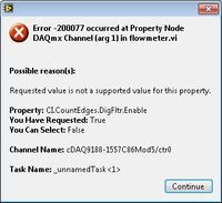
Debounce counter signal digital filtering is not possible?
Hey all,.
When you read a flow meter signal at lower bitrates, the signal bounces. Because these bounces are count in addition to pulse correct, this leads to an output of counter unreliable. With a range of joint, I can see the behavior that bounces and determined that the rebounds are starting to occur around 100 Hz. The flow meter has to be in the order of 1500 to 10 Hz. remove all other devices of the system with the potential to influence the signal has no effect.
Bounces produce both on the edge of the fronts and.
Because I use a 9188 compactDAQ chassis and a meter module 9411, it seems that it is not possible to use the digital signal filtering? I want to establish that it is a correct assumption.
When adding a digital camera filter (see the attached VI) I get the following error, explaining that the activation of the filter is not possible.
Upgrade to DAQmx to 9.2.3 makes no difference.
I read about using a meter of output to generate own impulses (with a high enough to avoid pulse width bounce) here. For me it is not an option that I don't have an output of the meter module.
Are there other ways to get a correct count of edge output of the signal bouncing?
Kind regards
Bram bolt
Dear Bram,
You're right, digital filtering is not supported with the second chassis cDAQ generation (like NI 9188), I forgot that one (I tested with a chassis 0172 and worked well). What we can do is to measure at the same rate and filter the glitches in the software, please marine following example .
Best regards
-
How to connect an International ST75 components fluid flow meter to the DAQ system?
Hello
I am trying wire a ST75 meter to my DAQ system consisting of a device PCI 6052E DAQ, SCXI 1102 b card and a block to connect SCXI-1300. 1102 b has four 249 Ohm resistors connected to channels 0-3 for use with the current of the flow meter signals.
The flow meter has two output signals 4-20 my and RTN, SINK, SOURCE and com connections The documentation is not clear how to connect the sensor to the Terminal Board, other than to say if the two output signals is used, one of the sons of RTN are used. So far, I can not get the signal from the flow meter to work in LabView, so I don't know if I have it plugged properly. Currently I have 1 wire OUTPUT on the Terminal Board + CH2, CH2 - wire to the chassis ground terminal and the COM lead on the sensor.
Thanks in advance.
Towards the end of the manual there are wiring diagrams:
SINK/SOURCE/COM are used for pulse ouptuts. It seems that there are two outputs, one for 4-20mA temperature the other for flow.
The one you need (flow) conjnction with RTN wired to use the + and - (or COM) your DAQ hardware.
-AK2DM
-
Hello
We have the following configuration: 9265 A sends a 4-20mA signal to an intrinsic amplifier (to boost the signal) which is sent to a positioner (device to open/close a valve). Of the positioner, the signal passes in channel 1 of the 9203 control, measurement of the signal. The 9203 the com is connected with the ground of the amplifier. The amplifier is powered by a power supply 24Vdc. On channel 0 & COM the 9203 a signal 4-20mA of a sovereign is measured to see the actual position of the valve. This rule is also powered by the power supply 24Vdc and therefore the 9265. (see attachment for the layout).
Channel 0 measure without any problem 4-20mA. Now the following applies until 11.6mA 9203 fine measurements on channel 1. Anything above the 11.6mA is not measured. Disconnect the sovereign (channel 0) has no influence. Using a multimeter (Fluke 787 ProcessMeter) to measure the signal (I replace the 9203 with multimeter) gives me a perfect up to 20mA cadence. What can be wrong? We have two 9203 and both have the same problem!
Help, please.
First of all thanks for your thoughts.
We managed to solve the problem; It seems that the maximum impedance of the system could reach up to about 680 ohms while our amplifier was capable of processing 500 ohms.
Replaced by one of the handles, that a maximum of 800 ohms and the problem has been resolved. We have a very nice part of our specifications.
-
To connect to the Net material MKS Alta 1480 mass flow controller
I have a mass flow controller MKS Alta 1480 (MFC), manual of MFC, Labview 8.2 and the NI PCI - CAN card. I know that the MFC wired correctly because I can work using another program on the PC that uses the deviceNet interface. I want to talk to her through Labview. Everything looks OK Explorer measure. I have the range OR DNET. I know that the MACID. I downloaded the EDS of the manufacturer.
Here is what I am missing: a general idea on the DeviceNet interface. Is there a code of example out there that could help me get started? There are tutorials on how to understand the Dnet Protocol? I'm used to control serial--> response devices. I don't know anything about the class, object, attirbutes.
Thank you
Joe
Normal 0
Joe, you can read the MFC object sensor analog-S Flow value.
Class Id 49 0 x (31), Instance Id 1 (0x01), attribute Id 6 (0x06)
The default data Type is integer and units of data's counties
Normal 0 if you want the reading of the assembly object, you're going to have establish polled i/o connection, then read DeviceNet IO.vi allows you to read feeds.
Maybe you are looking for
-
My UN-jailbroken iPhone 6 has been hacked
Yes, Yes, I know what you mean... "there is no such thing as a malware on an UN-jailbroken device. Well well, my iPhone 6 has NEVER been jailbroken! I woke up the other night to the sound of a click on my phone. I was at the hotel and on their wifi (
-
My home page opens in Japanese. How can I change to open in English?
I just downloaded the http://www.mozilla-europe.org/en/firefox/ UK version.My home page presents the Japanese text only - I am currently in the Japan, so I guess that Firefox shows Japanese by default - but I want English.How do default to English?Th
-
An unexpected error occurred during the generation of the Volume License Installer
I'm building a Volume of NI Developer Suite 2016 DS1 License Installer. I created the master suite and the installer from the DVD device drivers successfully. However, when I try to create tools Xilinx DVD separated issued with the Game Developer on
-
Unable to connect to one of the 3 accounts
We can get our administrator account and my account, but the 3rd account won't open a session. I tried to reset the password already. The error message reads-user profile Service service has no logon. If we put the wrong password, it tells us that it
-
Security options updated... when we can create/modify security in E9 options?
We have some problems with people with access to all the emails/lists/etc. We want to be able to lock things more firmly and I was wondering when this ability will happen... that's what has been applied to the E10 with the last update, and if so, wh