Help explain the flow meter VI
After a lot of tinkering, I seem to have developed an effective VI for use with a type/pelton turbine flowmeter. The flow meter outputs a stream of pulses which
can count on the counter of my 6501 line. Unfortunately this eureka moment happened somewhat by chance, and I'm hoping someone
could be kind enough to explain step by step or in terms very simple for beginners (me) works of VI, thank you.
Kind regards
GER
GER,
Welcome to the Forums and LabVIEW.
If you don't the have already made, please work through the tutorials online to get started with LabVIEW. The answers to some of the questions you may have are probably there.
A brief description of your VI:
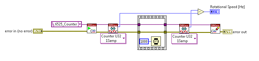
1. the overall structure is a loop For. It works for the number of iterations that is connected to the Terminal in your case 5 N.
2. the calendar of the loop is determined by the longest time required for any part of the code inside the loop execution. On the first iteration, the DAQ Assistant configures the counter and starts measurement. On all subsequent iterations, he reads everything simply an indictment. On these iterations, the 25 les 25 ms ms expect will dominate. This VI runs approximately 40 iterations per second (for 5 iterations).
This means that the program will take place on 5 * 25 ms = 0.125 sec and then stops. If you run for more 1/8 of a second to help run it continuously button, STOP. Which is intended for certain types of troubleshooting only.
3. the table of waveform and the flow rate meter only shows the last value of the five iterations. (This suggests also that you use run continuously)
4. the registers at offset in this VI nothing do. The upper shift register calculates the cumulative number of the flow meter, but the result is never used. The underpass registry has nothing connected to the Terminal inside the loop on the left. It could be replaced by a terminal.
Suggestions:
1. in order to avoid using run continuously, replace the loop with a while for loop. Add a stop button on the front panel and connect it to the stop it real terminal in the loop. Move the graphic terminals of waveform and flow inside the loop.
2 check your pulse to the algorithm of flow rate. The time for the count interval must be considered. For example if the meter registers 25 pulse in 25 Member States, which represents 1 000 pulses per second. This isn't which will show your VI.
3. see examples of code that uses counters.
Lynn
Tags: NI Software
Similar Questions
-
Looking for the flow meter liquid sensiron VI
Can someone direct me to a VI for a liquid of Sensiron meter? I use a DSM of 1600-20
Thank you
Thanks to the folks at Stanford and the University of Santa Clara, it works now, I'll join the vi
-
I'm in trouble during the expedition and listening to events in my application, I can send events from an object that is not on the display list and have a display object to listening to this event?
I do the following, I have a DataGrid component listening to an event he is sent to a non-visual object. the event contains information on the new dataProvider for the DataGrid, here is the code:
With the DataGrid component
"" < mx:TitleWindow xmlns:mx = ' http://www.adobe.com/2006/mxml ' layout = "vertical" width = "550" height = "600".
showCloseButton = "true" closed = "PopUpManager.removePopUp (this)" >
< mx:Script >
<! [CDATA]
import com.legosoft.events.DataProviderChangeEvent;
Import mx.managers.PopUpManager;
public void manejaEvento(event:DataProviderChangeEvent):void
{
pickListResult.dataProvider = event.newDataProvider;
}
[]] >
< / mx:Script >
< mx:DataGrid id = "pickListResult" width = "100%" height = "50%".
creationComplete = "pickListResult.addEventListener ('newDataProvider', manejaEvento)" >
< / mx:DataGrid >
< / mx:TitleWindow >
Here is the class that dispatches the event
SerializableAttribute public class GetTiposFacultadesCommand extends EventDispatcher implements Command, responder
{
public void execute(event:CairngormEvent):void
{
var delegate: BusinessDelegate = new BusinessDelegate (this);
delegate.getTiposFacultades ();
}
public void onResult(event:*_=_null):void
{
var _dataModelEvent:DataProviderChangeEvent = new DataProviderChangeEvent ('newDataProvider', false, false);
_dataModelEvent.newDataProvider = event.result.toArray ();
dispatchEvent (_dataModelEvent);
}
public void onFault(event:*_=_null):void
{
}
}
The thing is that the DataGrid never receives the event, I have no idea why it doesn't work. Can someone help me?The point is that I don't want to pass the instance of the GetTiposFacultadesCommand to intercept the event. The point is to send an event anywhere and be able to catch anywhere in the application.
I found a solution to this, I have created my own EventDispatcher object as a singleton in the application, whenever I want to send an event and be able to catch him anywhere, I get the instance of this object and send the event, anywhere I want to catch it I get the instance of this object and have to listen to it, in other words, I coded the EventDispatcher object is a generic object that will send and receive events allowing others to get this instance and do something for the event.
This object has a getInstance() method that returns the instance of this object, don't forget that it is a singleton, there is that only one instance of it in the whole application, any object can obtain this instance and send/receive an event. -
help explain the data in dba_histograms
Hi all
On Oracle 11 g 2, I need to understand the output of dba_histograms for a column with the base frequency histogram:
 COLUMN_ID COLUMN_NAME     DATA_TYPE    NUM_DISTINCT  NUM_NULLS    DENSITY HISTOGRAM
---------- --------------- ------------ ------------ ---------- ---------- ---------------
        94 DP_STR          DATE                    7          0 1.6182E-08 FREQUENCY

OWN  TABLE_NAME COLUMN_NAME    ENDPOINT_NUMBER ENDPOINT_VALUE  ENDPOINT_
---- ---------- -------------- --------------- --------------- --------------
FH   XF_TNOG_SL DP_STR         811              2456473
FH   XF_TNOG_SL DP_STR         1242             2456474
FH   XF_TNOG_SL DP_STR         1984             2456475
FH   XF_TNOG_SL DP_STR         2969             2456476
FH   XF_TNOG_SL DP_STR         3792             2456477
FH   XF_TNOG_SL DP_STR         4626             2456478
FH   XF_TNOG_SL DP_STR         5486             2456479


7 rows selected.

SQL> select DP_STR from FH.XF_TNOG_SL where rownum <= 10;


DAT_POST_
---------
05-JUL-13
05-JUL-13
05-JUL-13
05-JUL-13
05-JUL-13
05-JUL-13
05-JUL-13
05-JUL-13
05-JUL-13
05-JUL-13


10 rows selected.
My question here is that since it is a basic frequency histograms, shouldn't he be showing me the real 7 different dates and their respective frequencies instead of a number as 811, 1241 etc.?
ENDPOINT_NUMBER is defined as the 'number of histogram bucket' in the documentation. In your case a histogram of the frequency, this represents the number of lines for each bucket. Thus, the first compartment has 811 rows, the second bucket has lines (1242-811), the third bucket (1984-1242) lines etc.
The ENDPOINT_NUMBER is a digital representation (internal Oracle) DATE of this column values. Thus, 7 separate dates are represented in the form 2456473, 2456474, 2456475 etc.
Hemant K Collette
-
need help with the code "meter."
Hi I had this form of testing that executes_query on the new block instance.
See the image below:
[http://i95.photobucket.com/albums/l133/element81/screenies.jpg]
I have this code on the button (next question) that captures the selected answer and compare it to the correct answer and then move to the next record:
"If: blk_exam.radio_group76 =: blk_exam.answer_id then.
-message('correct');
-other
-message('wrong');
: blk_exam.score: =: blk_exam.score + 1;
end if;
next_record;
"
the problem is I want to create a score counter, but I do not know how to display it in the text (circled in blue) element.
p.s. I'll hide the score counter, hurt later use it to record the score in the database.
Ty in advanceHello
No, there are no gaps. In fact, there is error in your code.Scenario 1:
If the blk_exam is on the top of blk_score when I run the blk_exam form works with execute_query but the text of the note element is a bit turn off so I have to click on to a grey, she and her show '0' because of its first value 0 then walla pressing "next question" with my codes work... it increments...For this scenario, you use NVL then it will work as...
:NON_DB_BLOCK.SCORE_FLD:=NVL(:NON_DB_BLOCK.SCORE_FLD,0)+1;Scenario 2:
If I make blk_score on top of my blk_exam the text of the note element contains the value 0, but the test module does not work still... I had to click on any text element or anywhere on the form first seized execute_query and shows the question and choices... but then after that, it works well...So now don't need to keep the DB NO BLOCK on top just keep the issue/block on top. Normal then run query which is now to work it will work.
hope you can imagine the two scenario hehe...
Hope you can imagine the fault encoding ;)
-Clément
-
How to connect an International ST75 components fluid flow meter to the DAQ system?
Hello
I am trying wire a ST75 meter to my DAQ system consisting of a device PCI 6052E DAQ, SCXI 1102 b card and a block to connect SCXI-1300. 1102 b has four 249 Ohm resistors connected to channels 0-3 for use with the current of the flow meter signals.
The flow meter has two output signals 4-20 my and RTN, SINK, SOURCE and com connections The documentation is not clear how to connect the sensor to the Terminal Board, other than to say if the two output signals is used, one of the sons of RTN are used. So far, I can not get the signal from the flow meter to work in LabView, so I don't know if I have it plugged properly. Currently I have 1 wire OUTPUT on the Terminal Board + CH2, CH2 - wire to the chassis ground terminal and the COM lead on the sensor.
Thanks in advance.
Towards the end of the manual there are wiring diagrams:
SINK/SOURCE/COM are used for pulse ouptuts. It seems that there are two outputs, one for 4-20mA temperature the other for flow.
The one you need (flow) conjnction with RTN wired to use the + and - (or COM) your DAQ hardware.
-AK2DM
-
conversion of turbine flow meter
Hello
My apologies for the query, but this software is all new to me. I have a cDaq-9188 8 medium chassis containing several modules including 2 off 9401 counter modules, I run signal express version 6.0.0.
My problem is that I have 3 miniature flowmeters turbine (GEMS units FT-110 series) which give various pulse widths depending on what is the 5V square waves. I brought to the entrance of my 9401 and look of good signals so guess that's my express configuration signal which is the cause of the problem,
I connected the + ve and gnd outputs of the flowmeters Com, DIO1 + Com and DIO3, DIO0 + Com on one of my 9401 cards.
I can see the increment in the number of pulses on measurement & automation Explorer when I run test for this module Panel and watch the chefs of edge that my system can see the pulse from trains.
When configuring the express signal I need it to read in l/min, 58-575Hz corresponds to 0.5 to 5 l/min, but I can't seem to convert the pulse in l/min.
If I select DAQmx acquire > counter entry > frequency it gives me the possibility of updated the custom scale, but every time that I run it I get the error signalling DAQ assistant upward. I tried many synchronization settings with no luck. The only time where I have this power as successfully is using counter entry > County of edge, but I'm stuck on how to convert l/min as it has no function of scale (I know!)
Any help appreciated.
I think that he is referring to l/min in litres per minute, and I guess the Freq of flow are the values of this compilation on the scale.
If this is the case; Carl, it seems to me you must configure a custom scale. You can do it in the channel settings tab in the DAQmxAcquire stage. Under custom scale select Create new, and then select map scale. Min/max Freq should match your flow min/max.I have attached a few screenshots for reference.
Let us know if we are on the right track, otherwise we might need more information; FOR EXAMPLE. file seproj and a bit more info on the flow meter (type of connection, the output signal, etc.).
In addition, a brief look at the documentation on this flow meter recommends the use of a pull-up resistance. Might want to look there as well. -
Magnetic sensor to the top of analog frequency AC for Turbine flow meter measurement
Hello!!
I use the following hardware configuration to measure a flow meter flow turbine.
Material: 1000 SCXI Chassis
SCXI 1102 voltage input module
SCXI-1303 terminal connection block
Flowmeter: output signal is the frequency of the alternating current (30mv peak-to-peak). Sensor is a magnetic sensor type.
I tried to convert the signal of output voltage in the area of frequency using the FFT, but I get the wrong data.
I wonder if anyone can suggest good troubleshooting techniques so that I can understand what is mess up my position or my technique of measurement in labview itself will not completely? (From my understanding I think that I can measure the frequency of the ac voltage signal generated by the sensor of the FFT. By measuring the frequency I can calculate the water flow)
I am aware that a potential cause might be the ground loop in the system. The signal is based solely on the SCXI-1102 with factory default bias and pullup resistior network. I see no other reason reading wrong or fault in my measurment. Also the flowmter is brand new and there is no risk of damage to the sensor.
I'm sorry if I'm missing out on any important detail to answer that I am relatively new on the techniques of data acquisition.
Thank you
Concerning
Aditya
It's conditioning of signals... and that's what you want to do, so it's not so far

And if your signal about 30mV Ridge to Ridge, it fits perfectly in the beach of crete to 200mV Ridge... I wouldn't say no need of amplification... the + 100mV is not a minimum of signal, this is the maximum signal in this range
Hang it up, take a measurement in single channel mode with one all 10kSPS sample rate take 100ms (1000points) and feed in single tone detection...
display with a graph of signal, stop the vi, in the rigth diagram, click the graph icon and create a constant, save that in a vi and post here if you need help in signal processing
-
I recently created a form to complete for the app e-business of the company. When you press the button submit, he only sent to our Inbox to project and not sent to the e-mail provided in the URL. Can someone help us to program the key to help explain why / tell us step by step what we should do?
OK, I re-read your question. It's actually expected behavior. The user must manually send the email.
If you want it to be a silent process, then you must either install a script on the local computer of the user who will do this, or use any email but something as a service web to which you directly submit the form data.
-
Help for interpretation explains the release of the plan (dbms_xplan)
Hi all
I am trying to familiarize themselves with the reading and interpretation of the output of explain plan command or dbms_xplan, and so I hope someone can help with the output below.
With the command explain below, means that...
(a) he began to step 8 and sends all the lines of the loop nested in step 5
(b) but sends (or think it sends) 1 row in step 5 to step 8
(c) for each line that is provided in step 5, there will be a search index in step 8 to access the table in step 6
(d) step 8 gets only (or think it gets) 1 row
If that means that only 1 row is expected by the optimizer and yet the full table scan must return to 150 000 documents, and table a statistiucs to date, what else would cause the cardinality be far off?
If she does not mean it will return 1 row, then does that mean?
Thanks a lot for your help.---------------------------------------------------------------------------------------------------------------------- | Id | Operation | Name | Rows | Bytes | Cost (%CPU)| Time | ---------------------------------------------------------------------------------------------------------------------- | 0 | SELECT STATEMENT | | | | 945 (100)| | | 1 | SORT GROUP BY | | 1 | 283 | 945 (3)| 00:00:05 | |* 2 | FILTER | | | | | | | 3 | NESTED LOOPS | | | | | | | 4 | NESTED LOOPS | | 1 | 283 | 944 (3)| 00:00:05 | | 5 | NESTED LOOPS | | 1 | 108 | 929 (3)| 00:00:05 | |* 6 | MAT_VIEW ACCESS FULL | DEMOGRAPHICS_MV | 1 | 97 | 927 (3)| 00:00:05 | |* 7 | MAT_VIEW ACCESS BY INDEX ROWID| NAMES_MV | 1 | 11 | 2 (0)| 00:00:01 | |* 8 | INDEX RANGE SCAN | ORG_MV_IDX1 | 1 | | 1 (0)| 00:00:01 | |* 9 | INDEX RANGE SCAN | PAY_IDX8 | 252 | | 4 (0)| 00:00:01 | |* 10 | TABLE ACCESS BY INDEX ROWID | PAY_ALL | 1 | 175 | 15 (0)| 00:00:01 | ---------------------------------------------------------------------------------------------------------------------- Predicate Information (identified by operation id): --------------------------------------------------- 8 - access("ORG_MV"."ORG_ID"="DEMO_MV"."ORG_ID")SQL execution starts at ID = 6 with full scan on DEMOGRAPHICS_MV. This analysis should return 1 row.
Then, he expects to lead a nested loop to scan via the Index ORG_MV_IDX1 a NAMES_MV once (for 1 line, extracted from DEMOGRAPHICS_MV).
It then goes to PAY_IDX8 once where he expects to get 252 ROWID.
Finally, it accesses the table PAY_ALL.You should also post the main information because it is very important to understand access and FILTER operations for each operation.
Hemant K Collette
-
Chm file met poster "HTML help" on the title instead of the name of the window bar
Chm file met poster "HTML help" on the title instead of the name of the window bar.
I tried several ways such as:
1. modify the > project name settings and also set the language to English (United States).
2. check the name of the title in the .hhp file
3. use the window while compling.
4 Robohelp language settings.
5. also uninstalled and reinstalled robophelp.
But nothing helps
Title name appear correctly if the same project is compiled on another machine.
When the code in the high hydrostatic pressure and the locale on a correspondence of PC, the title OK is displayed. Or the other way around is also worth the title help is displayed in the language specified in the project IF (and only if) the regional settings of the computer matches the language. Otherwise, the "HTML Help" is displayed.
Hope this helps.
Thank you and best regards,
Rahul Karn
-
With the help of the meter from 6525 to measure the frequency: is there a more orderly way?
I am currently using the high speed on a module USB 6525 meter to measure the frequency of an object in rotation via a sensor hall-effect.
I was wondering if there was a simpler way / more effective this encoding than that?
Everything that I currently perform the current meter reading, wait a second, take another reading, and subtract one from the other. The result is the frequency in hertz.
Is there a way to get the 6525 to return the number / change County after 1 second?
Thank you
On the 6525, you have a country of the event and you can't make a measure of frequency.
-
How to connect a magnetic flow meter to a 9203 module?
Hello
I have a magnetic flow meter, which gives me a measured 4-20mA signal. I'm reading this signal using the 9203 module. As he wrote in the technical data I have to use external power supply. I have 2 sons of my August flowmeter + and GND. I connect August + food + and GND to AI0 after that - from feeding to Com in 9203. I am doing everything correctly? I see not all values change.
Thanks for any help.
Hi Rodzynek,
Have you tried looking at the output with only a voltmeter digital or similar on the output?
It would be a good guide to tell you what really is the signal.
The 9203 gives a FXP signal in amperes, so if you expect 8ma your jpg shows 7.16 to 7,74 my which is close.
As I said earlier, I found that the signal of the 9203 is rather noisy and apply filtering to clean up the signal, I guess thatâs you measure the flow rate of the signal change very quickly compared to the sampling frequency 9203.
Also check if the WHAT GND is connected to the MASS of other output signals.
See you soon
Stephen
-
stop the flow of ancient text to a new text
I have an iphone4 and trying to stop the flow of text from previous messages, when I write a new text to a contact.
Any help on this? Thank you.
momthood wrote:
I have an iphone4 and trying to stop the flow of text from previous messages , when I write a new text to a contact.
Any help on this? Thank you.
Please clarify - are you get over and over again old messages?
-
How can I remove another account icloud without the help of the person?
Hello, I need to delete an account from an ipad icloud. I had my nephew stay and he added his account for ipad from my mom, who she would now like to use. Unfortunately, it is unlikely to help me remove. There is no nice way to explain the situation, but basically, he stole a lot of things and ended up in prison. I have a number of crime when it was stolen, but the ipad was never because he did not leave the property. Of course, the ipad is not sound, is anyway apple will be able to help me? Thank you very much
If you were the original purchaser of the iPad (i.e. he not was purchased used) then you could try to go to an Apple Store (make a Genius Bar appointment if you do) or try to contact iTunes Support Online (http://www.apple.com/support/itunes/contact/) and see if they can remove the iPad on the account - they are likely to want to see proof of ownership before they could for example help original receipt with the serial number top
Maybe you are looking for
-
In the Explorer, a padlock appears to tell you that the information you submit is being encrypted and are not accessible by others - for example, if you log in to internet banking or go to a page to make payments online etc. Firefox offers protection
-
How does one select type or drag a window using the magic trackpad?
How does one select type or drag a finder window by using the magic trackpad? I can't find the finger combinations to do either. Thanks in advance
-
Compaq presario v6000 v6409tu disk hard bios self-test fail
Hello Windows xp no my pc compaq v6000 not starting and bluescreen showed a couple of times. I ran the BIOS (phoenix) disk hard diagnosis and the test failed. When I opened my HDD I noticed green rust as deposits into the connector on the hard drive.
-
Logitech webcam M/N VUBE-43is in use by another application and I cannot connect to it
I have a webcam logitech M/N VUBE-43, I used it on this computer gateway DX441S with windows vista family premium, but now I cannot CONNECT to THE CAMERA. The error MESSAGE IS: WEBCAM IS in USE BY ANOTHER APPLICATION! ANOTHER APPLICATION OF WINDOWS V
-
My cat went through my laptop and now my mouse does not work. I was the mouse that plugs into my laptop and it works, but not the pad... Help!