creation of several geometric model
I have different models and want to create a file of multiple geometric model
I'm unable to do so.
I downloaded the models
Please help me with it
Hello
I was able to create a more geometric models from the images you attached to this post.
To create a model of multiples, you must make sure that the files you select to add to hear several geometrical models example are geometric feature corresponding to models.
To create them, before adding them to the example, use the template editor, which you can access from the Start Menu > programs > National Instruments > Vision > Editor
Select the file > new model... and then choose the option "geometric matching Template (basic functionality) in the list.
Select your template image, or image that you want to extract the model from and go through the different tabs to create the model.
Repeat for all models to add to the multiple template file.
Once they are created, you should be able to use the example to create. I worked for me.
Best regards
-Christophe
Tags: NI Hardware
Similar Questions
-
problem with learning several geometric pattern
Hello users of Labview,.
My goal is to load different templates located in the target folder, create one or more models then, perfom some treatment (located in another file) image.
The example provide in file vision works perfectly but if I change the path, it seems impossible to create a multiple repeat. In fact, I got the following error message:Error 1074395628 has occurred to IMAQ learn several geometric patterns
IMAQ Vision: Image model corresponding invalid geometry.
Certainly, I do not understand a part but I don't know where is my mistake.
I add to the multiple associated model, an example of template image and the image to test.
Please, can I have a help or suggestion to understand this problem.
Thanks in advance for your help,
Best regards
Hi matriax,.
Good to know it helped.
Come to your questions,
-Yes, model geometric information, or even in vision assistant also will not work.
-In my code too, it does not work. The reason is explained below.
-Yes, model created with assistatn vision should also work.
Coming to the creation of a model, there are two geometric methods correspondent-function based and based edge.
-Labview code uses geometric based function while u have created the model in edge based method.
-If you see in vision assistant, settings tab, you have the type of algorithm two options. Select the base feature and you should be able to run it and then assistant labview and vision.
For more details on geometric matching please refer to http://zone.ni.com/reference/en-XX/help/372916L-01/nivisionconcepts/geometric_matching_technique/
Hope that helps
 let me know if you have any other questions.
 -
I have an application of machine vision, in which the geometric pattern match technique was used to find the target in the images of type variant.
as we know, we do a geometric model by model OR editor in the editor we can adjust the parameters of the curve specified settings to get the desired curves and we derive the custom box to ignore during the match. then we save the use of the same model in our application of vision.
Now my question is coming. When I program my request for the geometric game. I have specified the parameters of the curve for the entrance of the IMAQ Advanced Setup learn ringtone 2, of course, I have to adjust this identical to the model, but I don't know how we extract the geometric model. I tried all the methods, for example, I can read data custom, IMAQ get characteristics of the geometric model(it's just for the basic functionality? so is there even a VI based edge?), even at anasys PNG file formats! But I can't read the info of the geometric model by myself!
It is also illogical to adjust the CURVE SETTINGS manually again for the " IMAQ Advanced Setup Learn Pattern 2" after that I already have in the template editor OR!
Hello
Why do you need to specify the curve settings once again, if you have already built a model using the template editor? You don't need to use "IMAQ Advanced Setup learn geometric model 2 VI" to find games (see the attached example).
You can wire the 'curve settings' control to 'IMAQ configuration geometrical game model 2 VI', but the values are not used if wire you a Boolean true to the node "use learning curve settings" (it's like that by default). To prove it, I enclose a small program with pre-created model (using the template editor) for a geometrical alignment. The model and the test of three images are also included.
Try changing the settings of the curve with the 'use know curve settings' enabled, and you will see the corresponding score remains the same. Disable the Boolean control, then try to change the curve settings.
Also take a look at the detailed help for "IMAQ configuration geometrical game model 2 VI", specifically the "learning curve parameters of use."
I hope this helps.
Best regards
K
-
Research and correspondence - difference between 'Match' and 'geometric model Match "?
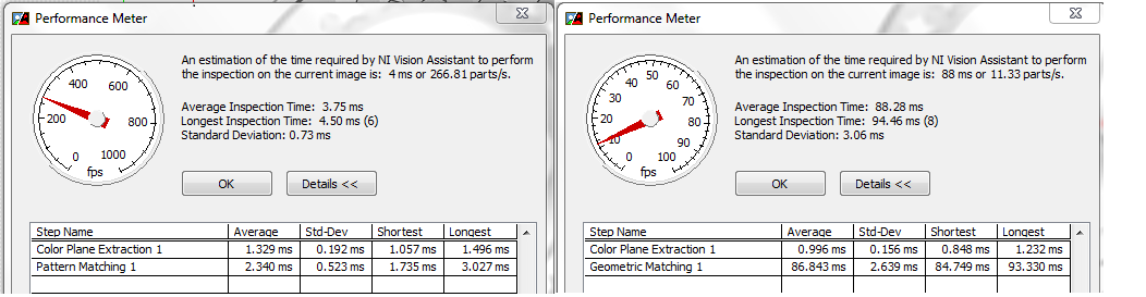
I was wondering if someone can explain to me the difference between 'Pattern Match' and 'Geometric pattern Match' screws? I don't really know how best to use for my application. I'm search/match small spherical particles in a video gray in order to follow their speed (I do that after subtracting the two following fields to get rid of background motion artifacts).
Which should I use?
Thank you!
Hi TKassis,
1. you can find from this link for the difference between these two,
Pattern match: http://zone.ni.com/reference/en-XX/help/370281P-01/imaqvision/imaq_match_pattern_3/
Geometric game: http://zone.ni.com/reference/en-XX/help/370281P-01/imaqvision/imaq_match_geometric_pattern/.
2. I always prefer the match pattern because of its speed of execution and incase of correspondence to the geometric model that it took a lot of time to match your result. You can find in the attached figure for the same image with these two run time algorithm.
-
How can I read a model and tell if it is a model of pattern match or a geometric model?
Hey all,.
I would like to know how I can read a template´s of information about whether it is a model macthing or a geometric model?
In my code, users of the models and the algorithm must match them using special or geometric criteria depending on the model.
For the moment I do by including a P or G file name, but I would avoid it and read the information in the file.
Any ideas?
Thanks in advance,
Esteban
Hey Esteban,.
You can use the VI "IMAQ is this Info 2 VI Vision" for Abboud information:
IMAQ is Vision present 2 VI Info - OR Vision 2011, using LabVIEW - National Instruments
http://zone.NI.com/reference/en-XX/help/370281P-01/imaqvision/imaq_is_vision_info_present_2/Take a look at the attached VI
Stephan
-
Hi, I had a problem in the creation of several rounded cornered rectangles not "distorted"?
Hi, I had a problem in the creation of several rounded cornered rectangles not "distorted"? I have attached a picture to show what I mean (problem highlighted in blue). Any help would be really appreciated...

Thanza,
If you wish to have proportionately more sizes with the same radius of rounding, you can:
1) begins with a rectangle (not rounded) and effect > Distort & Transform > transform with the setting to the desired scale and the number of copies;
(2) object > expand appearance.
(3) effect > esthetics > rounded corners with a desired RADIUS.
-
Creation of several objects in resource for OOTB connectors
All,
I am trying to create a second object of resource AD user for the STANDARD connector. I'd like to think that the connector AD (and all connectors, for that matter) has been designed to manage the creation of several objects in resource for the same Types of resources, but I'm bad? It does not appear the IOM connector can handle this easily.
Does anyone has created several objects of resource for a connector? It is a relatively simple task, or it will require a big effort? Is it still possible? Pointers?
Thank you!I'll give you a little help with replication. I found the best way to do is to import the original connector. Cross the diff鲥ntes pieces that each have a unique name, which is not part of one of the other names of piece. You must have unique names for the following:
1 object resource
2. process definition - commissioning
3 resource
4. form - process
5 scheduled taskAfter you import the connector, all of the following for renaming into something unique. I would also update your form of process to have a default value of your IT resources, as well as your scheduled task for point values to new unique names. Export the 5 elements, without addictions. The cards will be the same. Use find and replace the values, and then import the new XML. If it works, duplicate the XML file for each of the new workflows that you want to create.
-Kevin
-
Is the creation and use of several constants (string or numeric, say rather using two constants digital, conating the same value, in two places in the same VI stantdifferent, if I use a constant as common) affects anywaym on memory consumption or performance? What happens if the constant is large table?
I'm not sure what you're asking here, but each constant on the block diagram clearly requires is memory space for storage. The constants you have, more memory is needed. It oughn can't affect performance, however, unless you're talking about several hundred megabytes of constant data past autour.
Also - is there an alternative? When you need a constant, I can't imagine there is a more effective way to provide a more to use a?
-
Workflow to deploy several vApps model
Hi all. We have a new vCO + vCD 5.1 setting up the environment in my organization and I want to implement a simple workflow to Instatiate X number of vApps from a chosen model.
I'm a total noob/newbie here. The workflow library 'Instantiate VAPP model', that's exactly what I want it to do, but for only a paralytic.
Guidelines of thoughts as to what high level steps, I would need to take to customize this workflow for a number of times on the basis of "loop"?
It is quite easy to add a new entry and the introduction screen to enter the number of the user, but I really have no idea where to start on the loop.
One thing I want to avoid it is for a full to be created and launched upward VAPP and complete all tasks, and then it starts the next iteration of the loop (which would take forever). I would prefer instantiate the full number of vapps together and wait that fill them all, and then move to their departure at the same time and wait for all the startups end.
Any ideas or advice on how to come to this? (once again, total noob).
Thank you, in advance!
Here are step by step instructions on the top of my head. There are certainly other ways easier to do.
Create a workflow.
Do drag & drop the instantiate a workflow of VAPP model
Right click / Copy presentation wf.
-> You have wrapped the instantiate workflow in a parent workflow.
You can now remove the instantiate a workflow of VAPP model from a schema because we ask it with a different way.
Add the workflow 'Start the workflow at the same time' to your schema. Bind its entries 'wf' and 'settings' with the creation of new attributes of workflow. Settings, we don't have to be defined. To the ICF one set with the I ' nstantiate a VAPP model "workflow."
Add a script task. In this task scriptable entries add all entries in your workflow.
Create a 'number' entry in your workflow. Add it as well as your task scriptable entry.
Add an output to your box of scriptable and assign the attribute "settings".
We now need an array of input parameters to feed our workflows.
parameters = new Array();
for (var i = 0; i)
var wfInputParameters = new Properties ();
wfInputParameters.put ("vAppTemplate", vAppTemplate);
wfInputParameters.put ("vdc", vdc);
wfInputParameters.put ("name", name + number);
wfInputParameters.put ("description", description);
wfInputParameters.put ("deploy", deploy);
wfInputParameters.put ("powerOn", powerOn);
wfInputParameters.put ("eulaAccepted", eulaAccepted);
wfInputParameters.put ("runtimeLeaseHours", runtimeLeaseHours);
wfInputParameters.put ("storageLeaseHours", storageLeaseHours);
wfInputParameters.put ("linkedCLone", linkedCLone);
Parameters.push (wfInputParameters)
}
On the diagram, you should link.start-> special sriptable-> beginning of the workflows in parallel
-
SDO_Union on several geometries
Hello
I'm working if it is possible to run the SDO_Union function in Oracle on several polygons. The example of coding gives you only a situation where you are merging two geometries. I wonder if it is possible to merge polygons around 1 300 together by using a union query.
Any suggestions would be greatly appreciated.
Thank youI would use an aggregate function, like this:
select sdo_aggr_union(sdoaggrtype(t.geometry, 0.05)) as geometry from some_table t;In this way, all the geometries in "une_table" are merged.
-
Problem with the creation and application of models
For somrthing that seems so simple, I'm having a problem to create and apply a template to a page only.
First, I created a template as follows:
1. display a full page (index.html)
2 choose an editable region by highting the content area of the page. This excluded the header, the menu high horozontal, right bar and footer.
3. went to 'INSERT'-> model-> editable objects
4 name of container box editable and click on OK
5. FILE - > save all
The purple line was shown around the editable and the tag is displayed in the upper left corner of the combo box.
I assumed that the combo box has successfully been created.
Then, I tried to apply the model to a new page by using the following steps:
1 has opened a new blank page called about.html
2. went to: EDIT-> model-> apply the page model
3. selection of the Model dialog box displays and I chose the region to editible (1 illustrated)

4. After selecting the editable area, this displsays error:

Error message reads as follows:
Some Uea this document have no corresponding regions in the new document
I tried several times, but I know I have to do something by mistake.
Can someone help me in learning this task properly. Models seem to be such a powerful thing to use in development with DW.
Thank you in advance.
boblan1042
Try this method:
* FILE | New > template Page > select model > Create.
A step by step method that works every time. Once you familiarize yourself with the help of models, come back and I'll tell you why you receive the path you showed above.
-
Creation of several indexes of the columns of same
Oradocs a little wave, at least my current source.
When I create 2 indices of different types, example a bitmap another b-tree, on the same order of column, can both be running at the same time or if one of them must be invisible?
He can't do it on my own, I have standard edition that does not support bitmap indexes
Here:
CREATE INDEX fun1 on employees (last_name);
create fun2 index bitmap on employees (last_name);
Thank you
Oradocs a little wave, at least my current source.
Docs? I don't see a link to any docs. We cannot comment on something that we cannot see. Post links to "Oradocs" you are talking about.
When I create 2 indices of different types, a bitmap example another tree-b,.
on the same column order, both can be operational in even
time, or if one of them must be invisible?One of them may be visible. And several index on the same columns apply only to the 12 c.
The Blog of Tom Kyte: 12 c - more than one index column even...
-
Creation/deployment of a model of linux
Hi guys,.
Can you point me to a reference on how properly create/deploy a model of operating system based on linux? For windows, I created a basic OS and then converted/cloned it to a model. Regarding deployment, I placed the sysprep.exe on the appropriate on the VCS directory and then I can customize everything new deployments (host name, admin password, etc.) by using the created model. Is there a similar way of doing things for linux templates?
Thank you.
For the supported Linux distributions, you can customize the virtual machine (ex during cloning) or model (ex during deployment).
"Customization" tools are included in VC.
So tryied it with work also with derivation of RedHat (CentOS, Mandriva,...) and it works.
Andrea
* If you found this device or any other answer useful please consider awarding points for correct or helpful answers
-
Acrobat 9.3.4 question: unique PDF creation of several PDF
Hey all,.
My configuration:
• Mac OS 10.6.4 / Mac Pro dual / 6 GB of RAM
• Adobe CS5 Master Collection
• Acrobat 9.3.4 Pro
Just came across the (critical) question, I have not met before, but it is terribly reminiscent of the problem of the "policies of the Document" file issues and small caps Caps/All InDesign CS5. Here's the scenario:
1. in a document of IDCS5 I used the command "Uppercase" to give a position this feature (font is future 95 black; type 1).
2 export to PDF (Print) and receive a correct PDF, with the designation of all caps display/printing correctly.
3. open in Acrobat 9.3.4 and Adobe Reader 9.3.4, and the file is correct (see attachment 1, below).
4. I then do several other single-page PDF documents and keep them all in a new folder.

After you create these PDF files single page to review the customer, the customer asked that a random number of these PDF files be compiled into one PDF, which isn't a problem - it's a common request, we do all the time. The steps to do this are:
1. launch Acrobat 9.3.4 Pro
2. Choose file > create PDF > merge files into a single file PDF. dialog box appears.
3. click on the 'Add files' button in the upper left corner of the dialog box (the single PDF button is selected at the top right of the box).
4 navigation window opens, allowing me to choose the folder created in step 4, above, that contains PDF files, I need.
5. turn on highlight PDF files you want and arrange them in the order you want. Click the 'Combine files' button in the lower right corner of the dialog box. 6 PDF files is generated, and I save the file PDF. I then open it in Adobe Reader 9.3.4 or Acrobat Pro 9.3.4 to check that all is well and to my great disappointment, note the misinterpretation of the line type "All Caps" (see attachment 2, below).

I checked a PDF file that is exported through IDCS5 works correctly, and making the PDF "combined" by a new document IDCS5 and add the necessary pages and export a single PDF works fine, as well. The problem is that the function of «Combine...» "in Acrobat Pro is our workflow, because it allows for a PDF one being combined into one WITHOUT having to set up a new IDCS5 specially for the final PDF document. to do this would require countless file IDCS5 in order to get the pages selected randomly in a single PDF.
If someone has encountered this problem, and if I forgot one post, my apologies. Thanks in advance...
See you soon!
Mikey
The problem is related to incorporations of fonts. If all of the PDF files contained the game rather than subsets of fonts fonts this would not be a problem. How to approach the problem is to use the PDF optimizer to remove all embeddings of fonts. Then use the preflight to re - integrate fonts.
-
Creation of several end points
As a user of Captivate for quite long, I am really puzzled thread on something that is probably easy. Normally, I create linear kinds of sims in Captivate and use other tools when I need branching. However, with my purchase of 2 CAP, I couldn't wait to use it for my needs of ramifications. However, I can't understand how to create a slide that is not related to the rest of the project in a linear way.
In the demo for connection included with A2, it shows several paths that a correct from incorrect action can take. It also shows the specific paths that leave the main "timeline" to a single slide that becomes at the end of this path. However, I can't understand how "unlink" a landslide from the rest of the timeline so that the movie stops right there. (Of course, I can do so by simply have no action on this slide, but to do that does not create the same type of Visual demo shows)
In case this was not clear enough, here is more than an example. In slide 1, if I had two areas of click, I would want the A of click to take them on channel A, which has three other slides and then ends. I would like to click on B to move in the direction of B, which has only five slides more then ends. When I got to the top of the cylinder head, I can't understand how making the separate paths A and B. They are all still connected visually (and linear) and do not separate in the 'lines' that I see on the demo included with A2.
Can someone point me in the right direction? Thank you very much!Through experimentation, I found my own solution. It seems that you can create a 'distinct' line in the Visual display of branch by the link in the slide to less than 2 slides with either a success or failure, or a back button.
Once you do this, you now have a visually distinct 'line' that you can add slides to no impact on the rest of the "mainline".
Yet once, do not do to actually create branching, only if you want to visually SEE the separate lines in the branching vierw as opposed to a long "line".


Maybe you are looking for
-
If I sell my iPhone 6, indicating the error 53, for parts, should I worry about the person buying it have some sort of access to the personal data registered on this phone?
-
BootCamp "preparation-auto-repair" after the triple-boot Linux install.
Hi everyone and thank you in advance for your help, I'm pretty desperate here... I use a retina MacbookPro 13 "with dual-boot OS X el-captain and Win8.1 for years, with also a small third partition"shared file ". Today, I needed to install a small pa
-
Introduction to the programming of sbRIO.
How to start using sbRIO 9636 and its parameters of configuration and programming? Their tutorial is linked to the programming of sbRIO?
-
Lexmark s305 communicates only with the pc, how to fix?
all print jobs go to QC.
-
COOD109B error reading of an AVI file
get a cood109B error when I play the avi file