Distortion of the signal caused by the channels # sampled and sampling frequency
I am using an acquisition of data USB-6211 (250 ksps / s) and looking at the sample channels 3s 80kS. (Labview 2012)
When I taste one channel, it looks fine (1 Channel_Sampled First_250kS), but when I add another channel to be sampled, the signal is driven down and that it depends on which channel is sampled (2 channels (Different) _Sampled First_40kS and 2 Channels_Sampled First_30kS). Addition of channel 3, it pulls down even more. I also noticed that the sampling rate also distorts the signal the higher the sampling rate, the more the signal is driven down.
The acquisition of data IS sampling of signals "correctly" when I run my Labview VI my external hardware begins to read in correctly based on the distortion of the signal.
What is the cause and is there a way to fix this?
I have attached the waveform above captures and can post some if necessary.
Thanks in advance,
WBrenneman
That's exactly what ghosts means. The measurement signals later is affected by other signals. It happens usually if you have a high impedance input signal. Adding pads like you can help solve this problem by making the signal to a lower impedance.
Ghosting would probably look worse to the frequency sampling rates higher, just as you said that you had problems, as it provides less time between samples of the amplifier set new voltage level when the multiplexer allows to switch between input signals.
Tags: NI Software
Similar Questions
-
Discordance between the channel seen and Guide
XP removes an ariel analogue TV via a built-in TV card of WMC. My problem is that the image I see does not match the channel information displayed at the bottom of the screen. For example, the image is see is BBC2 yet display said information BBC1. While this isn't a problem watching live, I can't register the correct program guide. I tried the manual and automatic set up, but doesn't solve the problem. Anyone know how I can align the signal to the displayed information?
Hello
Follow the troubleshooting methods in the article below and check if this solves the problem.
Troubleshoot Guide downloading problems in Windows Media Center
http://Windows.Microsoft.com/en-us/Windows-Vista/troubleshoot-guide-downloading-problems-in-Windows-Media-CenterI hope this helps.
Thank you, and in what concerns:
Shekhar S - Microsoft technical support.Visit our Microsoft answers feedback Forum and let us know what you think.
If this post can help solve your problem, please click the 'Mark as answer' or 'Useful' at the top of this message. Marking a post as answer, or relatively useful, you help others find the answer more quickly. -
The channel numbers and the USB-6259 BNC
The front panel USB-6259 BNC labels BNC connectors as channels 0-7 and 16-23. Most odd... I have a software written in C++ using NOR-DAQmx that my client will try to use with this unit. When using the channel superior numbers he (not unusually, really) Gets the error-200077 saying that they can only be used in unbalanced mode. But it is not natural for him to use the channel numbers printed on the front of the unit.
Can someone tell me how the front panel of this device is the channel numbers, you must specify in the code?
This requires the switch (source of the source/grounded) floating FS/GS that appears under each BNC connector?
Here's my proposal: differential mode: in the software, channels 0-7 are front channels 0-7. Software 8-15 channels are front 16-23.
Asymmetric mode: software channels 0-7 are cover 0-7 and 16-23 software channels front 16-23. And 8-15 and 24-31 channels are absent...
It takes just the opposote of what you have. In differential mode, aix is paired with aix + 8. so, ai31, ai9, AL10, ai11, ai12, ai13, ai14, ai15, ai24, ai25, ai26, 27, ai28, ai29.ai30 and ai8 channels are not available for selection in differential mode. Front panel for ai15-23 labels should be correct and matches what you select in the software.
-
Read the channel 1 and channel 2
Hello
I went through the basic course Lab View 1 and I'm starting to understand some of them. I struggle to write the next request in Lab View 8.5 and version 2011.
I need to write a VI for the Tektronix TDS 210 2 channel oscilloscope to be able read channel 1 and channel 2 (x and y). Also, I have to run this scope as scope of digital storage (remember the waveform in the memory and be able to remember specific time range) I downloaded the driver for the scope and I am able to run the only form of wave or multiple wave VI, but I do not know how to change these VI in order to function as I mentioned above.
I need to know how I can lock this VI as the instrument always follows the same GPIB address.
Could someone help me with this project please?
Thank you
Joe
Make a constant on the block diagram. It is an option to click right when you are on the block diagram. I also recommend the creation of an alias for it to the MAX (i.e. "extended"). In this way, if the address changes, you don't have to change the program.
-
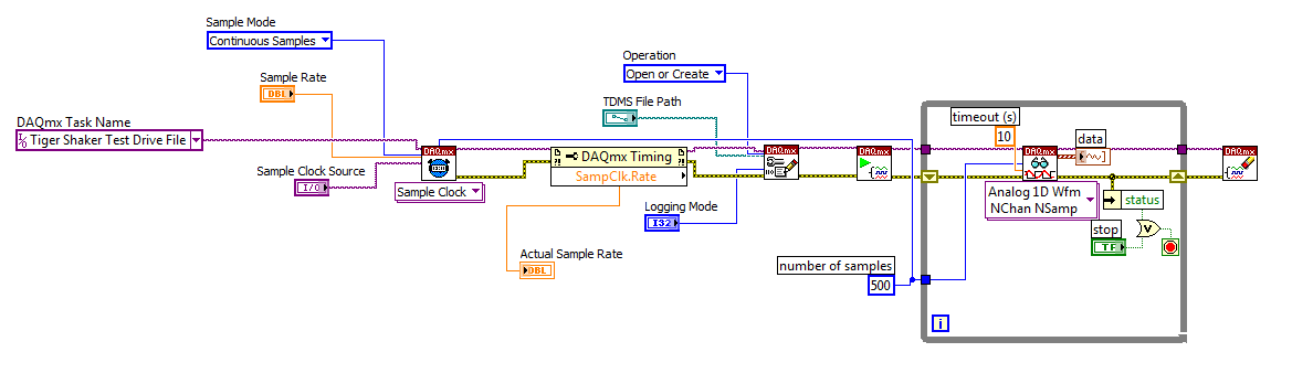
How to change the DAQmx sampling frequency
Hello
I'm trying to: record streaming channels (acceleration 21 and 1 tension) using a DAQmx task, then convert the data to a PDM file. The program files and output to the TDMS file very well. The issue I'm having is that I can't change the sampling frequency. I want to record 500samples/s and I can not get the "real sampling rate" of change of 1651.61samples / s. I am trying to use the clock to do this and I succumbed. I also tried to change the settings of "Timing" in the task without a bit of luck. Here is a screenshot of the .VI I created. I've also attached a copy of the file VI. Any help would be greatly appreciated!
Thank you
Tony
You will need to provide the model of your device. You can also look in the sheet/manual to see what the real supported sampling rates. Some devices have limited rates.
-
Cannot set the < 1609 sampling frequency
Hello
We have recently upgraded to LV 8.6 and 8.7 DAQmx and then you have problem with the acquisition of data that uses the DAQmx API. For example, we have a module HAVE cDAQ-9172 and 9239. The device can be specified by the user and a typical configuration could be a continuous CQI, one sample at 10 Hz. After the upgrade of the 200279 error "attempt to read samples that are no longer available... crushed" came little after the task was started. It turned out that the property sampleclkrate is not affected by the value that is put in the DAQmx Timing.vi, except if it has been set > 1612,9, if you set 10 100 or 1000 or whatever the sampling frequency will be always 1612,9 when you read in the property of timing.
If the buffer then of course becomes flew, but the question is why there is a minimum sampling frequency like this? Earlier, it was fine it set a value of arbitray and the acquisition would be at this rate.
There are a lot of solution to get around this (faster reading, etc.), but it is strange that the behavior of the code can change from one version to the other like that...
/ Henrik
I see a flaw in your program, you have the hardware timing and calendar in a software loop. The loop is limited by the expectation of the software. (I think it's on purpose for the demonstration).
I looked at the Manual for the 9239 and page 18 notice that the minimum entry rate is 1613kS/s
So that is explained, the only problem is that the timing DAQmx VI does not return an error or a warning when you set a too low rate.
Tone
-
NEITHER the 6602 write and read frequency
Hi all
I have NEITHER 6602 calendar card and I am trying to use it to write and read from the
DAQmxWriteCtrFreq (taskHandle1, 0, 1, 10.0, DAQmx_Val_GroupByChannel, & freq, & duty, & writtenVal, 0);
and
You should have the following sample installed on your PC that can help you in this task: DigPulseTrain - Cont.prj (it could be found in \program files\National Instruments\CVIx\samples\daqmx\counter\generate pulse folder)
-
What is the difference between the channel strip and an insert?
I'm confused a little, what's the difference?
All (from top to bottom) is a channel strip, in the red zone are two insert (effect plugin) s.

-
change the channel (string and array)
Hi I have a set of data with the type of data (.csv - somma separated) after being read with spreadsheet read (string game), it gives me:
Waimea, 21.625, - 158.025, 0, 299
Kahuku, 21.625, 157.9, 0, 566
Kaena Oe W, 21.5,-158.275, 0, 130... blah, blah
what I want to do, is to transform a string 1 d of the names at the beginning of this chain 1 d. Length varies found it is easier to find the length of the name is to search for the first occurrence of the decimal point, which gives the length of the name (+ 1) so I know how many characters I need to crop the starting off. And that's where IV ' e got stuck.
Is there an easier way to do it? Ideally I need a "remove table" for an operation chain, is - this posible?
Chears.
John P.
If you specify the correct delimiter (en) with the function of reading of spreadsheet, you would have a 2D array and you would simply use the Array Index function to get the column 0.
-
2015.0.2 question of image distorted in the source monitor and program when I double click on a clip
When I press play it continues normally but every clip I click the image looks like this... On OS X El Capitan 10.11 and 2015.0.2 first

Known issue with El Capitan.
Disable the MPE material in project settings for now.
-
How to save data quickly to the high sampling frequency
Hi all
I use a structure of producers and customers to measure and record the data. The sampling rate must be as high as 10 kHz. Given that so much data, it takes a long time before the data is saved. At first, I saved the data in an excel sheet. Then I tried to save it in binary, but it still takes a while to complete save. How can I make the time savings a short circuit?
Thank you
The best
First we will make some corrections to your DAQmx code. Since you are using continuous sampling, do NOT connect the samples per channel. Which is actually limiting your buffer. And there is really no need to define your buffer size either. It is default to very big, so this isn't a problem as long as you read your data quite often.
Now your data connection... You simply create a very wide range while acquiring data. Then, you save the data. It's actually not through the advantage of using the producer and the consumer. You should save your data in the loop of the consumer. It will be elinate need a lot of memory and you save the data to the file while you are buying.
But, in this case, I say that the producer and the consumer is not even necessary. Use the DAQmx Configure registration VI. With this VI, you can tell DAQmx to disseminate all data directly in a PDM file. You don't have to do anything. It is by far the best way to save on your DAQ data.

-
Change the Audio sampling frequency - post audio recording
Hello
Is it possible to change the audio to 2oKHz sampling rate after I taped audio? Is currently 44,10 KHz
Thank you kindly
Ali
I just found this today...
Under "Publish"-> click on the 'more' (button)->-> "Audio" and finally, select an option under "Bitrate:' '.
Bitrate (128 Kbps) CD
Near bitrate (96 kbps) CD
FM Bitrate (64 Kbps)
Custom bitrate (slider that starts at 32)
I changed a course of 68 slides in near CD Bitrate to FM BItrate and size of published file dropped to 50 311 KB 93 288 KB.
-
Hello
In the code in the example attached, I create a task with a single channel of AI.
I get the maximum sampling frequency using DAQmxGetDevAIMaxSingleChanRate (or DAQmxGetDevAIMaxMultiChanRate), both return the same value of 1351 s/s.
When I try to configure the sample calendar using DAQmxCfgSampClkTiming at the maximum sampling frequency clock he does not accept the rate and returns the following error. Note that the error message shows 2 channels, even if only a channel has been added.
OUTPUT:
DAQmx error:
Sampling frequency is greater than the maximum sampling frequency for the number of specified channels.
Reduce the sampling frequency or the number of channels. The increase in the conversion rate or
reduce the time of the sample can also mitigate the problem, if you define one of them.
Number of channels: 2
Sampling rate: 1.351351e3
Maximum sampling frequency: 675.675676Why the device driver thinks I have 2 channels in the task, when a channel has been added?
Please find the code to reproduce this problem attached.
Kind regards
whemdan
The MathWorks
Hello w,
By default, the ENET/WLS/USB-9213 in NOR-DAQmx module has the AI. AutoZeroMode the value of the DAQmx_Val_EverySample property. This causes NOR-DAQmx acquire the channel of the internal path of the unit (_aignd_vs_aignd) on each sample to return more specific measures, even if the operating temperature of the device moves over time. If you need the sampling frequencies higher than this allows, you can call DAQmxSetAIAutoZeroMode(..., DAQmx_Val_Once) (who acquires the formatting string when you start the task) or DAQmxSetAIAutoZeroMode(..., DAQmx_Val_None) (which disables the setting entirely).
Note that for measures by thermocouple with cold junction compensation sensor of the 9213 NOR, NOR-DAQmx acquires channel built-in CJC (_cjtemp) on each sample as well, for the same reason.
Brad
-
Formula to find the value of the channel
Hi all
Support: Dat file containing the value of time and acceleration. Now, there are only two Channels. Channel 1 is time. Channel 2's acceleration.
Step 1: Create more than two channels. Channel 3 and channel 4
Step 2: go to the analysis and acceleration channel research where its value is reached xxxxxxxx 1.
Step 3: where it has reached 1. XXXXXXXX in the process of accelerating from this point in the channel 3 and 4, paste all the values STD. STD values in the attached excel file.
How can I do this? What is the formula or the script to do this?
Thanks in advance.
Hi Rash.patel,
You didn't yet tell me where to find the Excel file, so I assumed it would be in the same folder as the VBScript script. I used the DIAdem Excel Import Wizard to create an *.stp file that can be passed as parameter in the ExcelImport() command to load these curves 2 envelopes by program. I also added a file dialog box, then you can select the *. DAT to deal with file.
I think that's
Brad Turpin
Tiara Product Support Engineer
National Instruments -
Import data from txt file and name the channels
Hello
I want to import data from a file txt (see attachment). Well well, no proplem, but I want to also read the information on the channel names and units and rename the imported channels. Is it possible to do? It is also important that the number of channels may vary.
Can someone give me some examples of code?
Thank you very much
Gabriel
Hello Andreas,
Thanks for your work. I'll adjust the code.
Gabriel


Maybe you are looking for
-
Impossible to update my itunes
When I try to update my itunes I get the following message is displayed: Cannot install the updated "iTunes." The file 'iTunesX.pkg' could not be found on the server "swcdn.apple.com". This is preview of my computer. Presentation of the material: Mod
-
How can I create my own theme full (I know how to create background themes)?
-
Satellite C50T-A382 - updated to Win 8.1 Pro & touchscreen support
Dear all I am currently the owner of Toshiba Satellite C50T-A382 machine which has preinstalled Windows 8.1 edition in plain language. I now want to upgrade to Windows 8.1 Pro Edition, however I'm worried if updated to Win 8.1 Pro, it will support no
-
the value of Listbox fonts at design time
Is there a way to set the font for all the lines of a ListBox at design time? I found some examples on how to do it programmatically, and I was able to do by changing each line at a time.
-
All I know is that I have Vista. I'm not an irritable person, so I have NO idea where from here!