Documentation on the extended functions - Siebel
Pls someone has a doc that has a syntax and other details of the extended TONE employed functions when it is integrated with Siebel?I understand that they are defined in the XLSFunctions.jar and called thru the psfn: in the field code.
TXS for any help.
Antonio
The blog too has examples and some extension functions. I don't understand what you mean by «no syntax»
He covered the steps on using too.
For the complete list, see note MOS "Siebel Reporting XSLFunction Methods [1435271.1 ID]"
Tags: Business Intelligence
Similar Questions
-
I have Adobe Acrobat Reader DC 2015.016.20039 on my system. I filled a form using Foxit Reader. When I tried to open the form with Adobe Acrobat Reader DC I received the error "the document enabled extended in Adobe Acrobat Reader DC features. The document has been changed since its creation and use of the extended functionality is no longer available. Please contact the author for the original version of this document.
I tried other PDF programs, no problem at the opening of this form.

Function "Activation reader" comes from the original shape, and it's essentially a digital signature. It is specific for the free product of Viewer PDF by Adobe (aka Adobe (Acrobat) Reader).
The problem is that only Adobe products are able to (re) make these documents without breaking the seal of the digital signature.
So, what happened in your case is the Foxit Viewer broke the seal during the recording of back and what's. Using Acrobat, you can save a copy of the form, and then continue will fill. Otherwise, you will be better off to start over, but stay with viewers Adobe PDF all the time, working with the form, or with a different Viewer, once again all the time you work with the shape.
BTW, player XI and most recent no. have more need of extended for more rights blocked by previous versions of Reader. This is not enough in this case; only, it would be useful for the sender of the form.
Update (after rereading of the original message): if it's just for viewing or print the form, you can ignore this message. You can also try to save just, you have a version of player who no longer has the rights extended (at your risk).
I hope this can help.
-
incomplete documentation of the Callback function plans
The third paragraph of (CVI2010) help with callback function plans says:
The main callback function is the only type of callback function that responds to the EVENT_END_TASK. Windows only, this event occurs when the user tries to exit Windows.
This information seems incomplete: EVENT_END_TASK also occurs if the program is closed via the taskbar button.
Thanks, Wolfgang. We'll fix it.
Luis
-
Satellite A100-220: is it possible to extend with the WLan functionality?
As in the title: is it possible to extend the Satellite A100-220 - without builtin WLAN - with the WLAN functionality?
Hello
It is not a problem to use the WLAN option on the unit without internal WLAN card. You can also use the little USB WLAN stick. It is very small and easy to configure. Before you buy something to pick up the info from your local dealer.
-
Function documentation for the SignalExpress project
I use the function 'project documentation' LabView SignalExpress 2009 in my application project.
The draft measure a pressure signal permanently in different situations. I want to present my project document is a list of locations of the siganl of pressure taken under different situation, with a plot for each situation so that readers can easily compare the plots.
For example, I want the document states:
~~~~~~~~~~~~~~~~~~~~~~~~~~~~~
At 10:00 at low flow:
ground pressure siganl
At 11:00 with increased flow
the same pressure signal ground
etc.
~~~~~~~~~~~~~~~~~~~~~~~~~~~~~~~
What I did was flirting with the pressure signal in my documentation of the data acquisition phase in the project tree, but in doing so, I could only show the last parcel of this signal in my documentation, the plot is in real time, just like what shows in the display of the data.
Is there a way to show the same siganl taken at different times in a documentation?
Thank you!
Hello
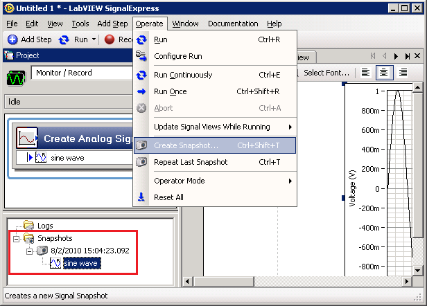
You can totally do this by using a feature called "instant."
Rather than drag the step signal directly in your project document, first create a snapshot of your data using the menu option "use > create snapshot...". (Ctrl + Shift + T) »
A dialogue will appear asking you what signals you want to instant. After selecting / them and clicked on Ok, your new snapshots will appear in the section overview of the application (in the left corner below, by default).
Drag these signals on your project document. When you are ready to create your next snapshots after changing the configuration, you can select "Operate > repeat the last Snapshot (Ctrl + T) ' to simplify your process.
For more information about the snapshot, see using LabVIEW SignalExpress found under "Help > LabVIEW SignalExpress Help" and search on the keyword "snapshots."
I hope this helps!
Phil
-
Is there a documentation about the configuration of the function keys (program)
Is there a documentation about the configuration of the function keys (program).
Dell Dimension 1400, model XP SK8110 keyboard. Yes, I know there are 7 years old, but running like a champ.
Hello
You can use various function keys to activate certain features and commands only. The following list details the current functions keys, what they do, and when you can use them.
Three keys can be used when Setup is loading and when you are prompted to press the F6 function key to install some third-party small computer system interface () SCSI and host controller drivers:
- F5 - for computer type or hardware abstraction layer (HAL) selection
- F6 - to install the SCSI controller drivers and third-party host
- F7 - to run Setup without Advanced Configuration and Power Interface (ACPI)
When the "Welcome" screen is displayed, the following function keys can be used:
- F2 - to automatically start the process (ASR, Automated System Recovery).
- F10 - to bypass the menu screens and to load the Recovery Console
During the GUI (GUI) - Mode Setup, the following function keys can be used:
- SHIFT + F10 - to enable access to a prompt during the installation in graphical Mode
- SHIFT + F11 - to display "old" wizards that give more detail.
Thus, it is not possible to configure the function keys to perform this task. However, you can use your favorite search engine to perform this task.
Warning: Using third-party software, including hardware drivers can cause serious problems that may prevent your computer from starting properly. Microsoft cannot guarantee that problems resulting from the use of third-party software can be solved. Software using third party is at your own risk.
-
Libretto W100: extended functional button is unavailable
Hello
I can't used the two screens as a large screen, I did extend functional button on the top of the application window.
Also automatic rotation does not work too...I tried to enable the option in the settings of the booklet, but nothing has changed (windows 7)
Have you any suggestions?
Thank you very muchCeucile
> I have not extended functional button on the top of the application window.
.. .and why you don t have this button? Have you changed something?
If you want to use the system pre-installed, this button should be available.I n t have this camera, but I've read here in the forum that you can just switch between the screens by simply tapping on the function button on top of the application window.
You can switch between mode double full screen (two screens as a large screen) and double (two screens in separate windows) simple mode using the active window
-
When I use the library function node call in real time, is loaded only once for all or load the DLL every time when it is called?
I have a critical application in real time, in which I use a piece of DLL function developed in C++. It is ok? Make sure any senior developer?
Thank you in advance.
The user interface thread is the thread that is used to update the user interface. It's slow. And it's supposed to be that way because humans are slow.
The call library function node can be configured as this thread to use in the configuration for it dialog box. Please visit the LabVIEW documentation on how to do this.
-
I use the node of the library function call in LV 8.6. I checked the path to specify the box diagram and made directly in the DLL file that I use. Whenever I have started with Labview, I have to go to the diagram and physically find the DLL in one of my calls to make it work properly. Once I have do this everything seems to work as expected. Anyone else see this issue? Any suggestion would be appreciated.
Thank you
Steckman wrote:
I use the node of the library function call in LV 8.6. I checked the path to specify the box diagram and made directly in the DLL file that I use. Whenever I have started with Labview, I have to go to the diagram and physically find the DLL in one of my calls to make it work properly. Once I have do this everything seems to work as expected. Anyone else see this issue? Any suggestion would be appreciated.
Thank you
Probably that DLL does not depend on other DLLs that reside in the same directory you point to in the configuration node dialog box call library. What is happening is this:
Without going into this directory:
LabVIEW applications Windows to load the DLL, Windows detects that it needs to load other DLLs and can not find in its standard search sites:
(1) already loaded into memory
(2) in the application directory (where the exe that began the current process resides in the LabVIEW IDE would be where is LabVIEW.exe)
(3) in the system directory
(4) in the Windows directory
(5) any directory in the PATH environment variable contains
(6) in the directory 'active '.
Because Windows cannot find a person to load DLL he abandoned the main DLL loading and returns an error to LabVIEW.
Now, you go to the configuration dialog box and point to the DLL. The dialog box browse file in LabVIEW uses the standard OS dialog box and this dialog box has the behavior obnoxious always update the "current" directory in the directory where a file got selected in. LabVIEW sees now that the path has "changed" and asks again to load the DLL. Yet once, Windows detects that it needs to load other DLLs too for this DLL but this time going over the search order, it will actually hit the DLL in the same directory and that's all fine.
It is certainly NOT a problem of LabVIEW. LabVIEW does not and should not really need to know that a DLL needs other DLL loaded and more importantly should never try to think he can do better than Windows, it probably could, but is simply not his task of dependency DLL loading.
It is your responsibility as a programmer and user of this DLL to know its dependencie, and if you did not write the DLL, to hit the original on his head programmer, if it has not documented these dependencies and make sure that these dependencies are actually properly resolved for Windows placing them in one of the places mentioned above
((2) is generally the best location for applications applications because it will not pollute the Windows directory or the user of the application system and 5) is the best for the development machine as you can add a directory to your PATH environment variable where you put the dll you need to develop a specific application.
Rolf Kalbermatter
-
The power spectral density function counts inaccurate amplitude caused by the window function?
I'm new to this forum, so please let me know if this would correspond better to a different discussion forum.
Here's the question:
I would like to know if the power spectral density function ("FFT PSD for 1 Channel.vi") automatically compensates for the loss of the amplitude of entry caused by the window function. In other words, is a specific window correction factor applied within the PSD vi or do I apply manually?
Details of the background:
I tried to answer the question myself by generating a sine wave sampling, it as it is periodic in record time (i.e. 0 to each end of recording time). The frequency of the sine wave was such that the frequency would exactly correspond to a spectral line in the PSD. Then I generated the PSD of the sine wave twice: once using a Hanning window and once using a rectangular window (not on average in both cases). The rectangular extent of the PSD with windows to the frequency of the sine wave is 1.5 times the size of the PSD with a Hanning window applied.
The experience above indicated to me that a manual setting of the PSD output for the function of window was necessary, however, I repeated the above experiment using random vibration data and does not clear 1.5 x factor. I have also been informed by his colleagues that the PSD should set for the window function.
Thank you for your comments.
Spectral leakage. When you use a finished sample data from the spectrum resulting is the convolution of the spectrum of the signal as if it extended indefinitely in time with the spectrum of the window. Even if you do not use a window function, you actually have a rectangular window the same width as the sample size.
Draw out of the VI PSD with all style of trace to show points to the data points. Turn off Auto scale on the X axis, and expand the graph around your pic. Look at the results of different windows. In any case, there are several values non-null. With actual sampled data of limited duration, you will never get the idealized line spectrum.
If summarize you the output spectral value remains close to 3.2 for all windows.
Lynn
-
Documentation of the API for CWIMAQControls
I am a software developer with several years of experience in medicine and other sciences, but now is working on a software project using National Instruments IMAQ customer in .NET and have no prior experience with image processing. The only I can find the API documentation is a help file with the product intalled. Then this under did a good job explaining the service inputs and outputs, it is light on the explanation in a real retail functions actually do. Under .NET (not my favorite but this is what I got), I can get a good summary of the objects and their properties / methods, which is useful. I see there are a lot of good material in this forum, but what I need right now is good basic documentation. I also noted a plethora of PDF files in the directory of installation but found nothing there or on ni.com which gives me the level detail fo I need. When I think that the documentation of the API, I expect something as complete what Sun Microsystems offers with any JDK Java - it seems that the doc API IMAQ assumes a certain level of ease and does not for someone like me come with literally no background outside a lot of math (algebra of vector fortunately!) and science in College courses.
Am I missing something? I see that there are many examples of programs and I can get what want from those, I guess, but I do not charge my client for all the time it will take, if there is a more ready fo source information.
Now, I realize that the field of the treatment of the image is large and it would be difficult to develop a software of this nature without a learning curve. So I have
I studied through two web queries image processing and having bought the book 'Digital Image Processing (Gonzalez, wood).
Specifically, I was put to zero in on what is needed for the task at hand: "blob detection" and "blob tracking movement." It seems pretty clear to me, some have become familiar with the image processing basic terminology and methodologies that have been developed for tracking, and image recognition of movement IMAQ software can do what it takes. At this point, I can do basic things with objects presented in .NET. It is analogous to maybe ask a kid who just the definition of an equilateral triangle to solve differential equations.
In this case, what I really need is one or more examples of programs that perform functions similar to what I want to do. Is there any suggestions in this regard? My research on ni.com revealed evidence of the items of "blob detection" and "blob motion" and I see that these were used for tasks as complex as the particles of follow-up and the counting of blood components. I don't see and od you expect not to see any object, follow also specific methods than what I need to do - which is in fact quite abstract - and chart the path of the blob more to light to the camera image gained when it moves in real time.
It's a strange feeling to have been programming for decades, and then enter a field where the customer needs require me to act as a nini who has not done its homework. But it's the nature of the job. The pointers will be appreciated. If I missed something obvious I don't even mind being reprimanded to be unobservant or lazy.
Thank you very much in advance for any assistance that may be provided.
tsfarrell-
Have you looked at the manual of the Vision Concept? (it should be in the form of PDF in the documentation directory, or you can see it here) It has a more detailed description on what our algorithms.
We also ship many examples for .NET - those of the 2. Functions\Binary analysis file dealing with blob detection and may be useful.
Good luck to you on your application!
Greg Stoll
Vision R & D
National Instruments
-
The doc for the function of the subset of the table shows the extensible function
In LabView 2010 the doc for the function of the subset of the table shows that the function is expandable with indexes and multiple lengths. I can't expand the function for multiple indexes. How can I do this?
Is the documentation for the function by mistake, or is there another function of a subset of the table somewhere that can do this?
Subset of table details
When wire you an array to the function, the function is automatically resized to display entries index for each dimension of the array. If wire you a table 1 d to the function, the function displays the index for an item entries. If wire you a 2D to function, the function table displays the entries index for a line and column, respectively. If wire you a 3D through the nD to the function, the function displays the index for a page entries.
-
How can I use the BCGTransform function to treat the 16-bit Image?
Hi ~
I use LabWindowsCVI8.5 and NI Vision to make the treatment of the Image. When I read the "IMAQ Vision for LabWindowsCVI Reference Manual", I found that the imaqBCGTransform function only supports 8-bit Image, while I do the BCG to turn on 16-bit image. Are there solutions to use the BCGTransform function to deal with the 16-bit Image? Or any other feature that could make the correction Gamma, contrast and brightness on the 16-bit Image?
Thank you very much!
because imaqBCGTransform is implemented as a lookup table, we can understand why it is limited to 8-bit images.
Now let's take a look at the definition of each of this mandate (from the NI Vision Concepts documentation):
-brightness: a constant added to the components red, green, and blue pixel of color over color, decoding of the process;
-contrast: a constant multiplication factor applied to the components of the luma and chroma of a pixel of color in color to decoding process.
-gamma correction: expand high gray-level information in an image while removing information of low level of gray. (the chapter on lookup tables gives some examples of corrections gamma)
now that you understand that this transformation is a simple mathematical function, simply calculate the correction for each pixel on your 16-bit images.
I know not the exact formula used by the imaqBCGTransform function, but you should be able to approach by performing some tests on images 8 bits with the original function... or you can make your own formula... or find one on the net... or you can ask someone at home OR you give the formula...
-
Hi ~ I'm using LabWindows/CVI & OR vision. I want to apply false colors on my image of gray, but I don't know how to use the imaqSetWindowPalette() function. Are there examples? or a better idea? Thank you very much ~ ~ ~
It depends on what you're trying to achieve:
1 imaqSetWindowPalette() change the palette to display only. This affects the display, but still, the underlying image is grayscale.
a simple use is:
{
const int window = 1;
Image * image;
/ * retrieve and store your image * /.
...
/ * change the palette * /.
imaqSetWindowPalette (window, IMAQ_PALETTE_BINARY, NULL, 0);
/ * display the image * /.
imaqDisplayImage (image, window, TRUE);
}
as specified in the documentation, the third and the fourth parameter of imaqSetWindowPalette() are used only when the pallet type is set to IMAQ_PALETTE_USER, in this case, you specify the colors you want to use for the display.
{
/ * declare and fill you the palette * /.
RGBValue palette [256];
/ * fill your palette here * /.
palette [0]. R = 0;
palette [0]. G = 0;
palette [0]. B = 0;
.alpha palette [0] = 0;
palette [1]. R = 255;
palette [1]. G = 0;
palette [1]. B = 0;
palette [1] .alpha = 0;
/ * etc * /.
/ * Use the palette * /.
imaqSetWindowPalette (range of the window, IMAQ_PALETTE_USER, sizeof (palette) / sizeof (* palette));
}
fixed palette, you can also set you palette with an initializer:
RGBValue palette [256] = {{0,0,0,0}, {255,0,0,0}, {0,255,0,0}}; / * you write 256 color values you want your palette consists of * /.
2. If you want the palette to be final during the recording of the image with the new applied palette, you can specify the palette in the call to imaqWriteFile().
3. or you can convert your image to RGB (imaqCast()) then... you're on your own: for some unknown reason, the lookup table in a call to imaqCast() converting grayscale 8 bit RGB is not documented as being used. error in documentation? removal of the deliberate feature? Finally, you can test what happens if you specify one.
-
Using the eval() function in Table DDL Transformation Scripts
Hello
I would like to run a stand-alone file java script in the script after you create and the events of the end of the Script. According to the Oracle documentation, there are several ways to do so: https://docs.oracle.com/javase/8/docs/technotes/guides/scripting/prog_guide/api.html
Only the first way seems to work:


Suggestions, please
Alek
Hi Alek,
you try to use the JavaScrpt JavaScript eval() function eval() function
and as I see that it works as expected. You need to get your engine and use the eval function.
Following works for me:
var manager = new Packages.javax.script.ScriptEngineManager();
engine = manager.getEngineByName("nashorn");
s = engine.eval("1+2");
fr = java.io.FileReader("d:/temp/inc.txt");
k = engine.eval(fr);
Philippe


Maybe you are looking for
-
Debugger JavaScript charging sources
The integrated JavaScript debugger seems to reload the sources when you view them. I'm working on a web app quite old, and I'm unable to use Firefox development tools as a reload of the scripts (particularly inline scripts) in the server results send
-
Failed to open completely zooworld on facebook. Plug what am I missing?
I got a new computer with Windows 8.1 and I used Mozilla before playing Zooworld, but I can't use it on this one... can't find add necessary.
-
HP MINI 110 FATAL SYSTEM ERROR STOPPED. [redacted]. !!!
HP MINI 110 LAPTOP FATAL SYSTEM ERROR STOPPED. [number of Series edited by Moderator] Please someone SOLVE THIS PROBLEM. I HAV NOT OPEN MY LAP FOR 3 months...
-
Computer HP laptop 15-ay007tx. : 15 ay007tx keeps not not fresh?
Hello! I have HP laptop 15-ay007tx bought a week ago. I observed a curious behavior charge with this laptop. I left my laptop charge overnight (in shutdown state). In the morning, I started my laptop just to check the load and it has shown 100% charg
-
my CD-ROM drive is corupt but to date what do ido?
Device Manager indicates the cd-rom drive is corupped or missing. (code 39) when I try to update the message says that it is up-to-date. the cd/dvd drive does not even until computer under any more.