EEG as waveform array
Hello
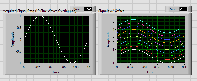
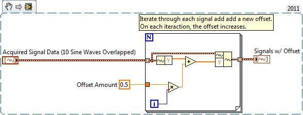
I would draw Let's say 30 EEG signals on a single waveform chart. Without the route option stacked, the signals that I can cross eachother but must have a lag... Is there a standard way to do this? I can give each signal a time lag, but I was wondering if there is some waveform table "xcontrol" out there with these features? Each EEG Viewer has its graphics of teas ways.
Best regards
Thijs
You could provide by program each EEG waveform with a lag, if she's not an impact on your data. My thought is that you can browse your waveform data table and gradually add known offset at each curve, which grows in proportion to the number of iterations.
Something like below:
Tags: NI Software
Similar Questions
-
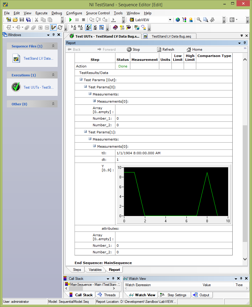
[BUG] TestStand 2013 receives corrupt data to LabVIEW adapter if the cluster contains waveform array
Hi all
I am having trouble with the corruption of the data. My minimal test case is below.
I have a VI that returns an array of clusters. My TestStand sequence simply call this VI and connects to its output:
When I run the (with my open VI) .seq file, I can see the update of the Panel before LabVIEW with expected values:
However, TestStand receives all these values. Waveform bays have the correct values, but everything else is empty / null:
If I delete my typedef waveform table, all elements of the cluster are correctly registered by TestStand.
I've attached an example of test (2013 TestStand, LabVIEW 2013) case.
Any ideas on how to make it work?
Hey JKSH,
Thanks for the detailed on this report. I looked into it a little bit last week.
I think that it is closely related to the 206892 of CAR, which describes a problem where data will not appear on the report unless a property or variable is specified for the output waveform parameter. However, this does not completely cover your case, because you see incorrect digital data in the row with the waveform of your cluster. I filed 462209 CAR for that matter, and we will investigate it more thoroughly.
This problem only affects data that appears "below" the waveform in the cluster. In the case of the sample, if you put the waveform as the last element of the bunch, I think that it works correctly. I know that your real data could be more complex than this example, but this workaround solution would help in the meantime? You could also consider separating the waveform of the rest of the data, that would probably work too.
As I said, please let us know, and it is classified in our system now for a developer to investigate the matter. Please let me know if solutions are not appropriate for your application, we would be happy to know a little more about your overall use case order to work around the problem.
-
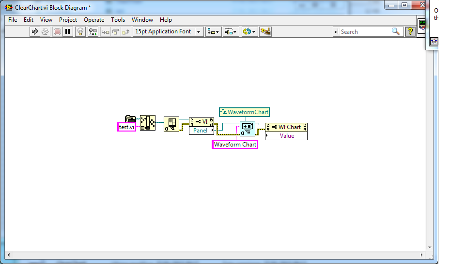
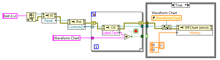
Open the waveform array Vi object reference
Hi, I would like to change a property of an indicator in a VI of VI another (in particular I want to erase a waveform graph), I used Open VI object reference, but I'm not able to access the data in the history. How can I do?
OK, sorry for the confusion between you. I haven't checked the strict reference waveform with reference open function.
Using the "good old way" works:
Norbert
-
Indicator of waveform data dashboard with multiple locations
I have a chart in waveform with multiple locations on my main VI running.
I use the Application Dashboard data 2.2.1 on my Ipad to monitor table of wave shape of my running app. I placed a marker on my Ipad and also related waveform with my waveform array variable. I can't play my data dashboard application because it shows unable to connect to the server. I noticed that it is because of multiple plots being plotted on my table of waveform.
I could only play the App data dashboard when it is just a single parcel related to an indicator on the App.
My question is if it's possible to have a graphical indicator of waveform on a data dashboard that has several plots being plotted and not only a single square, and how to configure it?
Thank you.
Click on Bravo and select as an accepted answer. You are welcome.
-
Addition of waveform with adding block - element wise or interpolated or...?
Hello
I see the block addition is beautifully overloaded to overlay waveforms and I would like to know how it works. Specifically, I want to know if using matrix addition (i.e. simply by adding the elements of each waveform) OR is he among the waveforms by interpolation and resampling to the points of time corresponding to the other or another method.
I know that the sampling interval (dt) should be the same for both waveforms added, so I suspect it is using matrix addition, but don't know.
To add a bit of context, I use this to add two waveforms of sampled data of a sinus waves up to 100 kHz. Sampling faster than my DAQ can exploit the difference in the two waveforms of departure time (t0) is an important part of the period. At this point, I think that the approach by adding simple matrix will not work.
Thanks for any idea that you can give. See you soon
-ron
Hi Ron,
I don't think there is a VI that does it for you. However, it should not be too difficult to program yourself. There's a Subvi, called 'Get waveform components' that allows you to access the table variables (Y) t0, dt and the data type of waveform data. You can subtract the two start times to find the difference between the two waveforms (DAQ readings put a timestamp on the data). Then you can complete the table operations to create a lag in the data. A few other useful subvis are "Get the subset of waveform" or "Index Waveform Array", you can use depending on how you want to set up your program. Let me know if you need help with this programming. Good luck!
-
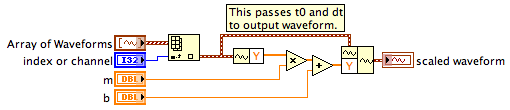
How to extract data from waveform
I have prepared a VI for acquisition and analysis. I have data from NI 9203 manuplate (power source). I have to use a lot of channels and more than 1 sample of a channel so Daqmx read vi out of waveform module and it is not a choice for table 1 d. How can I this form to scale data and display 2 diffferent scale given in a graphic waveform?
The DAQmx Read returns an array of waveforms. Each waveform is t0, dt, Y components and optional attributes. See the palette of waveform for tools to extract the components and build waveforms.
To make your scaling that you do these things:
1. Select the waveform you want to scale by using the Index table or index of waveform Array.vi.
2. download the component Y of the selected waveform.
3. resize it if Y' = m * Y = b, where is the original painting and the Y' is the matrix to scale. You can use the standard digital functions for * and + because they work for arrays and scalars.
4 build a new waveform using Y'.
Lynn
-
Setting the properties of elements of façade in XControl to a VI that uses the XControl
Hi all
I'm new to XControls and I try to use them to make a generic digital indicator that fit into a matrix of waveforms of a similar measure and allow the user to display the first value of a waveform, it chooses by selecting the name of the desired channel in the waveform table. I have the XControl work, with a ring filled automatically with the NI_ChannelName of the input waveform array fields and the value of the ring being used to index the waveform table to select the appropriate data.
What I want to do next is automatically set the value of control of ring in the XControl to the value that the user has selected the last time he ran the VI that uses the indicator. However, the properties of the control ring do not seem to be accessible from the VI that uses the XControl, and none of the XControl General properties seem to be accessible from the front VI in the XControl. The value of the ring is not part of the entrance of DataIn cable waveform table, so I don't have a good method to pass data to the control of the ring outside of what is in this table of waveform. I might add the value in the waveform table, if this helps, but indicators XControl do not transmit their return DataOut appellant VI to allow me to record the user selected value.
Is there a good way to read and write the properties of façade elements in an XControl of VI that uses the XControl?
I apologize for not posting my code; the computer with LabVIEW license is having network problems at the present time. I'll post the code when I can.
Thank you!
Erik
In your State cluster typedef container, include a reference to a control of the ring.
In your vi of façade, in the case of change of Direction, create a reference to your ring and connect to a plan by which he sends out the view state. Also be sure to write true to the status changed in the result of the Action.
In your xctl, select New-> property. Name it after the property in the ring that you want to access. Use the view clustered State (in your new property VI) to access the reference to the ring; son of a property node. Change the control value in the appropriate type & connect to the property you want.
Be sure to connect the path error through everything that might cause an error.
When you drop an instance of the xctl and create a property from this node, your new property will be available.
-
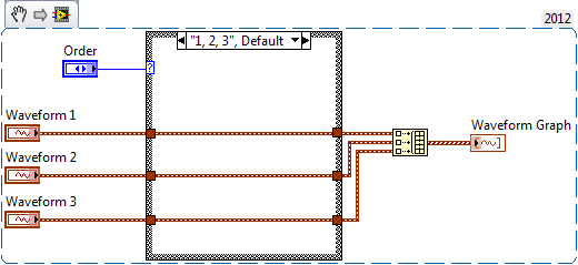
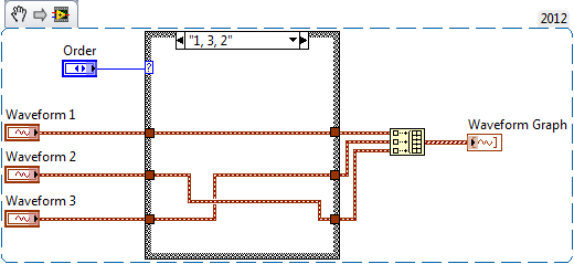
Sorry for what can seem like a basic question: I want to clarify where an analog channel is found in the data file, column wise. Right now I'm dealing with 4 channels, 0,1,2,3 and the data them file acquires in the columns from left to right, 0,1,2,3.
I want to spend the 2 and 3 as they are written to the file by using a control on my FP. So... 0,1,3,2. I use 'write to the measures' and tensions is my signals. Any ideas?
If you have three separate signals, you can combine them using table build as follows:
If you get all the waveforms as an array of size N (i.e. of the same analog input task), you can index the table and proceed as above.
Edit - point being, it's the order in which the waveform array passed to write to file measure is based which determines the order in which they will be saved in the output.
-
How to create a waveform from an array with arbitrary sampling rates
Hi I know that sounds a little silly,
Suppose I created a simple table of figures DBL with a structure For, Say size 16. now, I want to create a waveform DBL with these 16 numbers at an arbitrary sample rate. so if I use 1 kech. / s to the sampling frequency, I want to have a waveform with a duration of 16 milliseconds.
Please help me, I need it too
TNX
Hello
You must use the wave to build function as shown here: http://zone.ni.com/reference/en-XX/help/371361G-01/lvwave/build_waveform/ . Wire you your Board at the entrance Y and then wire the dt of entry in your sampling rate.
-Zach
-
problem with the history of EEG waveform data
Hello world:
I use SIT to create a user interface in Labview to communicate with a simulink model. After I configure the SIT connection manager and run the vi, the output was displayed in waveform graph.
Now, I want to get all the data in the history of the map of waveform. I tried to use the graphic story property node to access the whole of the historydat. But nothing copied in the part of Y in the front of the cluster of waveform...
Can someone give me a helping hand on what is the problem? or has anyone encounter the same problem when you use SIT. I am really confussed...
I've attached the vi, but to run the vi, you must have a simulink model corressponding and SIT, so I'm really sorry that you can not run it
And thanks a lot a lot a lot for that.
/ Shangning
I just realized this data is a 2D waveform table, which contains the waveform 2000 * 1, and each waveform data contains only 1 value of Y.
-
How to add the phase parameter to array of waveform in the DaQmx continuous output example?
Hi all
I'm quite beginning to Labview. I just wanted to know how can I add stage information for the module of waveform existing as shown in the example of output Voltage-Continuous DaQmx.
SEEE attached, I thought that the "output" is actually a built-in control, is there anyway I can add the phase as an additional parameter which?
Thanks in advance for any help.
Eric
If you press ctrl + H, the context help window opens, and you can hover over the generating function VI to see its inputs/outputs, but also to navigate to the detailed help. As you can see from this screenshot, there is an exit for the phase which is separated from the output waveform.
-
Hallo!
I tried to put entries generated in a table with the current value of the time stamp in the first column and the data of a table 1 d of waveforms of 4 cards in the other 4 columns.
I have some difficulties to match the data in the table. I ve simulated the code I've written and I see that the time stamp but I ve got none of the values of data in my table. I want to ask you what you think of my code and how can I achieve my goal?
Corresponding VI is attached below.
Thanks in advance for the answer.
I think you're looking for it.
-
Waveform manipulation of the bytes in a byte array and display in 16 bit int signed in a chart
Hello, I read in two bytes using a VISA READ and then output is a string. However, I want to be able to access these bytes individually because I need left move the first octet 8 places and then add it to the second byte and then left move their sum 4 places to the left gives me a 16-bit signed int. Then I need to do this show in a waveform chart. Can anyone help please?
-
Array of strings to waveform curve
Hi all
I use LabView7.0 and need to trace the channel data on the waveform graph. I fix the image of the table that contains the data. The table or the data in a table is of type string, he got the date, time, and data from all 16 channels at that time. My requirement is to draw date hour n of all folders on the x-axis and its corresponding value in the chain on
y - axis graphic waveform.
.
Kindly give me example code and brief details to develop the same otherwise, I will be stuck in a large
mess

Kind regards
John
-
Construction of a waveform in a bit array and and noise sometida
Hello world
I have a binary table 1 & 0 and I want to build a wave of her form, each pulse with an interval of 500ms, adding little noise, how can I get it?
LabVIEW version 2010
Thank you
Maybe you are looking for
-
update not install 6464.msi windows 7
Windows 7 cannot install updates or uninstall
-
problem install shared printer on windows 7 64 bit
Hey guys I recently got a thinkpad IBM with Windows 7 Professional 64 bit. We have a HP Laserjet 3015 which is shared on the windows xp professional computer. I can't install on my computer. If I connect the printer to my computer via the USB port,
-
Satellite A200-PSAF3A cannot install XP SP3
I have an A200 - PSAF3A laptop computer which came with Windows vista, but also a disc provided by toshiba downgrade to XP. I used the disk and followed the instructions to downgrade to XP Prof SP2 successfully. I am now trying to install XP SP3 as a
-
lost my volume icon must return
Pavilion Notebook, Vista, explore. Volume (megaphone) always at the bottom of the desktop icon has deserted. Need again. Can anyone help.
-
I can not access my account im logged in as temporary profile, brightness, my operating system is windows XP, I have two user accounts admin and user, user account has administrative power, when I am connected to the user automatically signed in unde