Finite sampling on each trigger
Hello? I have a problem of error about DAQmxSetReadOffset().
Whenever I put this code,
short* DataBuffer = new short[_countof(dbuffer)];
...
DAQmxErrChk (DAQmxCfgSampClkTiming(taskHandle,"",fRate,DAQmx_Val_Rising,DAQmx_Val_FiniteSamps,_countof(dbuffer) ));
...
I get this error:

_countof (dbuffer) is a data buffer size. I wish to acquire _countof (dbuffer) sample size.
I tried this, but no use.
DAQmxErrChk (DAQmxGetReadAvailSampPerChan(taskHandle,&reading));

if(reading>_countof(dbuffer))
{
DAQmxErrChk(DAQmxSetReadRelativeTo(taskHandle,  DAQmx_Val_MostRecentSamp ));
DAQmxErrChk(DAQmxSetReadOffset(taskHandle, -(_countof(dbuffer)) ));
}
Ah, I solved the problem. He used a while() condition, but it causes this error.
Continuous sampling must while() but in this case, it didn't need it.
Tags: NI Software
Similar Questions
-
redeclenchables out initial varaible on each trigger with delay
I'm trying to implement a redeclenchables generation digital pulses of the train on 6363 PCIe with LabVIEW with the additional feature of an initial delay variable.
For example:
-J' have a fixed pulse train
-After the 1st trigger, it is generated without delay
-2nd after trigger, there is a delay of 10µs
-Each subsequent trigger increases the delay of 10µs
I tried to do by writing new samples to the digital output, which include an initial delay. Since it merely controls how the buffering is managed this does not seem to work reliable with reboot and redeclenchables ouput.
Is there another way to do this using a perhaps additional internal counter for the generation of delay?
Thank you
Christoph
I would look at using an additional counter that your delay generator. There is a counter property called
Delay 'auto increment Count', which lets specify you such a regularly increasing. Here is one
DevZone article and example that should help get you started.
The idea is that the extra meter comes between your initial trigger signal and the
pulse train finish that you want to generate. The additional counter made its own triggered impulse
with time growing after the initial trigger and your finite pulse train gets triggered by
This additional counter output.
-Kevin P
-
Hi all
Can you give me the will of fire CREATE TRIGGER sample once and not "for each line.
I find this example in the docs:
It is still ok if I remove the clause "for each line?CREATE OR REPLACE TRIGGER Emp_count AFTER DELETE ON Emp_tab FOR EACH ROW DECLARE n INTEGER; BEGIN SELECT COUNT(*) INTO n FROM Emp_tab; DBMS_OUTPUT.PUT_LINE(' There are now ' || n || ' employees.'); END;
as in:
Thank you very muchCREATE OR REPLACE TRIGGER Emp_count AFTER DELETE ON Emp_tab DECLARE n INTEGER; BEGIN SELECT COUNT(*) INTO n FROM Emp_tab; DBMS_OUTPUT.PUT_LINE(' There are now ' || n || ' employees.'); END;
KinzYou missed to add the statement FOR EACH ROW.
What happens if you write:create or replace trigger backup_config_trg01 before UPDATE ON backup_config FOR EACH ROW begin if :OLD.BACKUP_USER_ID != :NEW.BACKUP_USER_ID or :OLD.BACKUP_USER_PASSWD != :NEW.BACKUP_USER_PASSWD or :OLD.DB_SYSTEM_PASSWD != :NEW.DB_SYSTEM_PASSWD or :OLD.MAIL_SERVER_ADDR != :NEW.MAIL_SERVER_ADDR or :OLD.BACKUP_SIZE_WARNING != :NEW.BACKUP_SIZE_WARNING or :OLD.VALID_DAYS != :NEW.VALID_DAYS or :OLD.REPORT_DAY != :NEW.REPORT_DAY or :OLD.REPORT_TIME != :NEW.REPORT_TIME or :OLD.WEEKLY_EMAIL_ACCOUNTS != :NEW.WEEKLY_EMAIL_ACCOUNTS or :OLD.DAILY_EMAIL_ACCOUNTS != :NEW.DAILY_EMAIL_ACCOUNTS or :OLD.DAILY_REPORT_TIME != :NEW.DAILY_REPORT_TIME THEN IF :NEW.CHANGE_FLAG = 0 THEN select '1' into :NEW.CHANGE_FLAG from dual; END IF; END IF; end; /It is working for you? Or, if possible, let us know your table structure, so that we can try to help you.
Concerning
Girish SharmaPublished by: Girish Sharma on Sep 4, 2012 16:11
Published by: Girish Sharma on Sep 4, 2012 16:16
-
Hi all
A complex project I have to implement an interface acquisition of material for a linear motion sensor using the output of the synchronous serial (SSI) commune in the control of the industrial movement. (I have a bit of experience in digital electronics, but I'm new to hardware synchronized timer e/s digital in LabVIEW).
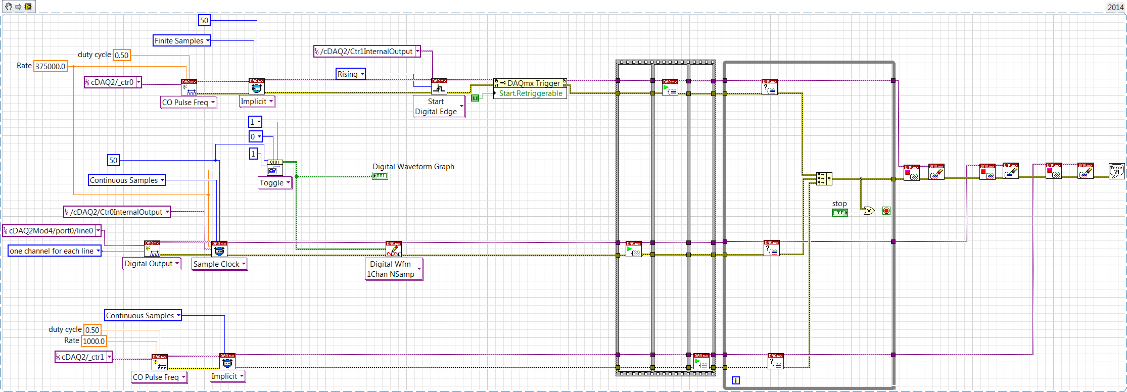
To do this, I need to create a clock timed by the busted hardware signal pulse train TTL. Each burst consists of 25 down transitions, with a period of complete cycle of 2.67 microseconds (375kHz). The output is then held high until the next outbreak, that produce at 1ms intervals.
Using of cDAQ timers and a NI 9401 (based on the example http://www.ni.com/example/30256/en/), I was able to create the pulse train burst as described (see attached image VI). Then I need to configure another timer to set off this explosion to repeat at 1ms intervals.
Someone at - it guidance on how best to accomplish the hardware timing for the repetition of the pulse train?
Any suggestions of alternative strategies or observations about the way that my noobish code is stupid or ineffective are welcome as well!
Thank you!
Hello RyanBiggs,
You will need to perform the following operations based on the code that you have joined.
- Set up a second output continuous counter task which will give an impulse to 1000 Hz.
- Set up your first task of meter output to start according to the configuration in the first step using the vi DAQmx trigger.
- Configure the first task of the meter output to redeclenchables via the property node so that the output meter pulses when he sees a rising from the second task of meter output.
The implementation is shown below.
Kind regards
Izzy O.
Product Support Engineer
NI.com/support
-
I can't stop finite samples daqmx read between the two?
Hi all
I want to read data from 10 seconds to a trigger is received. for this im using daqmx task finished sample mode and read the data on the trigger getting. It works fine but I can't stop my vi between the two when its reading of the data. I have to wait for it to complete the reading of values, and then stop the vi.
so I switched to continuous sampling mode that allowed me to stop the vi whenever I want.
I just want to know is there any means or the property using which I can stop my task over daqmx read when I want?
I guess you call DAQmx Read with extraordinary value (-1) for samples of #. It is also the default if left thread continues. In a finished sample task, it means to wait until the memory full buffer has been filled with samples before returning. Once you make that call, you cannot directly finish soon. You're stuck waiting for buffer fill or for the timeout expires (default 10 seconds).
One way to avoid getting stuck is not to ask for samples that do not exist already. You can query a DAQmx Read property, known as the "Samples available" or something like that and son of this result in a call to DAQmx Read. Such a call will return immediately whatever data are currently available. Subsequent calls will give you samples.
-Kevin P
-
DAQ read loop with finite samples
Hello
I would like to acquire the data of the instrument with a 6024E Board then put the peaks and which repeat at the highest frequency possible. The task of data acquisition is configured for sampling finished using a trigger, generated by the instrument (55 Hz) signal. When I use a VI such as demo_v1 (see below) everything works well but it takes about 200ms, just for the lu DAQmx VI to run.
It seems that begin the task outside of the loop (see demo_v2) helps reduce acquisition time, but it no longer works with over sampling. If I configure the task of sampling in continuous synchronization with the trigger of the instrument is lost.
How can I solve this problem?
Bernard
OK, thanks for the clarification.
Another clue would be to use WAS redeclenchables, which means that you combine a Counter task - that is redeclenchables - in order to generate a sample for your Acquisition of AI clock. For example a trigger of your instrument happens every time you take exactly 100 samples with the clock generated by the task of counter.
Christian
-
What is the best way to change this program and to read 1 sample of each channel?
The initial program was conducted with NOR-traditional DAQ. I change it to DAQmx the best I could. The program, he is already the application of voltage to generate code (Daqmx Write.vi). But I have problems with the acquisition of tensions, give me readings rare (Daqmx Read.vi) I don't know if I have to make a (Daqmx start Task.vi) for each channel in the program or if I can make it work with a single. Notice I have no significant changes a lot because this program is already running in another lab, and they send us the program so we had no problems so much but rather than get the BNC-2090, they got the BNC-2090 is who uses DAQmx instead of the traditional. If anyone can help?
A BNC-2090 is just a connection block. It has no effect on the question of whether you should use traditional DAQ or DAQmx. Which is determined by the DAQ card that you are connected to the terminal block too.
You can refer to this document, differences between the BNC-2090 and connector BNC-2090 blocks has, but it's just saying to change the label of the Terminal Board to reflect the new DAQ cards.
What problems are you having with the new VI you just posted? You get an erro rmessage? I don't know what mean "rare readings.
You really shoud look at some cases DAQmx in the finder of the example. Some problems that you are experiencing, is that your blocks of data acquisition are all kinds of disconnected. Generally, you should connect the purple wire from your work function of creation, through the beginning, reading or writing, then the narrow task. Many of your data acquisition functions are sitting there on the small islands now. You should also connect to your son for the error.
With DAQmx, you should be combining all your analogue channels in a single task. It should resemble Dev0/AI0... AI7. Then use a sample of channel 1 N DAQmx read to get an array of the readings, you can then use array of index to break.
Other things you need to do is to replace the structures sequence stacked with flat sequence structures. Turn on automatic growth for some of your structures such as loops. At the end of the day, you might find, you can eliminate some of the structures of the sequence.
-
HAVE high sampling frequency of trigger
Dear community
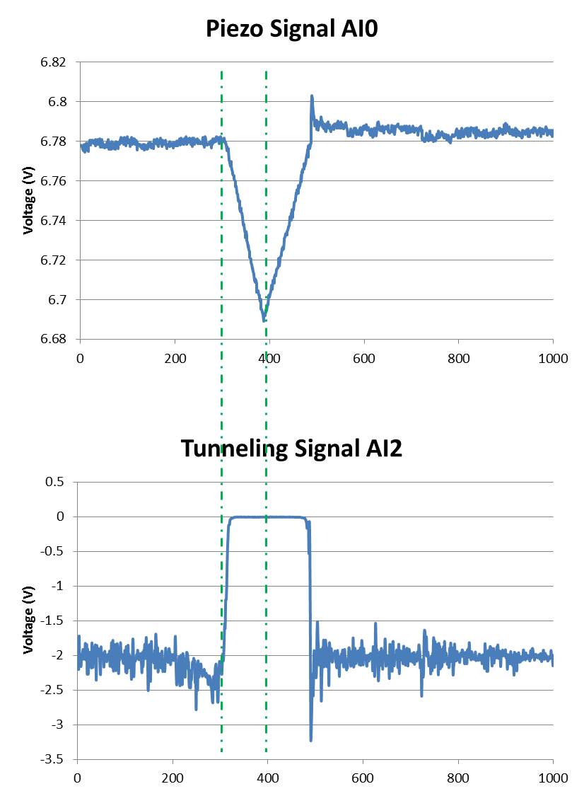
I am using a microscope to tunnel effect from here feeding two voltage signals on my map of acquisition of data USB-6212 (Labview 2013 SP1). A voltage signal is the voltage applied to a piezo in the microscope (AI0). This signal drifting slowly over time and it is noisy. The other voltage signal is a tunnel current is converted into a voltage (AI2) signal (see attached photo):
Ideally, I would like to record the two signals between the lines dotted in a .txt file whenever the event of tip in the top image rises. This should be about every second during a day.
So far, I've written a VI that calculates the moving average of the piezo signal and if the piezo voltage exceeds a certain percentage of the average running it fires a command 'Save as file'. The VI works well for a frequency of 100 Hz, but when I go to 20 kHz, the trigger does not work properly. I am also only watching a lot of a number (in this case, 1000) and if there is a trigger signal in these samples of 1000. So if there's a signal around 0 or 1000 I cut and split into two files that I want to avoid.
I don't have much experience with Labview and probably broke every rule of design in the book.
My question is if there is a smarter way to automatically back up the signal between the same dotted lines at high frequencies of sampling?
I thank very you much in advance!
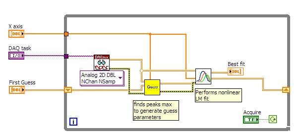
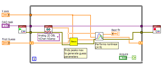
Hi Mario,.
I rewrote the portions of your VI to improve performance (we hope). No need to three queues. No inquiry unless there is a trigger occurs.
I'm confused by the outbreak that seems to detect the edges of the piezo signal high side, even if the tip is in the negative sense. I modified this logic (eventually) get a threshold top-side of the signal of tunneling.
It is unclear what might happen to 20 kHz. The example shows a constant 1 kHz sampling rate and 1 K samples treated by loop. If the sampling rate is changed to 20 kHz, then the loop will have to run to 20 Hz in order to keep up with the acquired data (@1 K samples per read).
I hope that the joint allows VI (not tested).
-
Download line sample for each recrd.
I have a table EMP
with columns as
GROUP GROUPNAME, EMPNO, EMP_NAME
Have the following data
GROUP GROUPNAME, EMPNO, EMP_NAME
1, eng1, 1, ZZ
1, eng1, 2, RR
2, eng2, 2, RR
3, eng3, 3 MM
3, eng3, 2, RR
.....
I need to select a samle of each record in the Group field. (each samle for Group 1, 2 and 3... (it is unlimited)
Output like:
1, eng1, 1, ZZ
2, eng2, 2, RR
3, eng3, 3 MM
....
How to get it?
If something is not not easy to answer me back.Do you care which line among several lines would you choose?
What version of Oracle?
You're really not a column named GROUP do you have? It is a reserved word in Oracle.I guess that something like
SELECT grp, grp_name, empno, emp_name
  FROM( SELECT a.*, row_number() over (partition by grp) rn
          FROM your_table a)
 WHERE rn = 1
would work
Justin
-
Read 1 k samples of 2 bytes each FPGA by UART
Hello
I'm designing a system composed of a board FPGA based (NEXYS4 DDR) which read high speed ADC via the parallel interface. Now, I programmed the FPGA for 1000 samples and send it to a LabVIEW GUI questioned by GUI via UART. Each content sample data 2 bytes so the finals will be 2000 bytes on UART.
At the moment I have not a syntax of separation between samples (to each 2 bytes), do I need? Then when I hit the LabVIEW acquisition he will show me the samples without separation between them.
How is the best way of? To make a separation in the FPGA firmware to each transmission of the sample, or to work with data in LabVIEW and do a syntax with a stacked sequence which will allow me to read 2 bytes and increment an index that will allow me to go to the next 2 bytes.I hope that I was clear where I have my doubts.
In this message, you will find a screenshot that show you how the data looks like when I receive the FPGA. In this screen printing indicator are defined to display the codes and hex display display and 028F is the value of the sample.Thank you in advance,
Vlad
Looks like you are doing things correctly. Just use Unflatten string to convert to a table of U16. I recommend using the Unflatten of string so that you can choose the endianness if necessary.

-
Software for reading and writing of trigger
Hello
My goal: generate a sine wave for output to a channel BNC-2110 (connected to a speaker), listen to the sound from the speaker generates via 4 microphones (separated by a known distance) and save lag (or the phase difference) between each microphone. The moment in this regard must be very precise, and I'm having a little trouble by issuing a command to trigger.
What I would do, it's the departure of DAQmxRead data and some time after use (controllable) DAQmxWrite start display the signal. This way I can see where the signal begins to write. I also want to make sure that the DAQmxRead continue to record a little after (also controllable delay) finishes DAQmxWrite, to make sure that I collect all of the signal.
Secondly, I would like to assure you that I am not wasting resources on my computer by continually check whether the signal DAQmx has finished sending, and so I'm quite happy to record using the method of the finite samples. If I know how long the pulse is + my two departure delays and find yourself, I can calculate the total recording time and finished so samples is good enough. Which should reduce to nothing the need for a while loop?
The process goes something like this:
--> Continuous playback playback--> continue reading--> reading of finishing--> output
Delay time known--> Start--> finishing Writing writtenMy main problem is that I don't know how to create a "dependent software time based event trigger", and I don't know how to make sure that each DAQmxWrite/reading is ready to start to go before I have send the trigger for them. Any suggestions?
AHA! The synchronization problem has been in the task. I had activated the recording and the default directory was not on my hard drive - I wrote continuously on the network! Works fine now.
-
Electric trigger DAMA IQ & check for new records to collect an infinite number of records
Hi all
I have some difficulties with the help of the trigger edge power IQ & questioning the DAMA if it has samples/records ready for pick up. I have reviewed the documentation on the support to the screw and the examples provided with the driver of the ACCA and have not been able to solve my problem on my own. What I'm trying to do, is to have this VI capture periodic RF bursts that are larger than a specified threshold.
I go to this topic in the following way:
I put the number of samples I captured (finished) for each burst which crosses the threshold
I put the number of records to capture to be infinite
I said that the rising slope and the appropriate threshold
I have then to validate the configuration of the ACCA and start acquiring
I have then go into a loop and check the backlog of samples as well as the acquisition is
If either of the above is true then I get the samples with the IQ extract complex WDT vi
I continue looping until the user stops the vi with a button on the front panel
I went on this path that I didn't block indefinitely or for long periods of timeWhat I see is:
I'll take one shot and then nothing else
what the samples never back above zero
that acquisition is ever complete
If I switch out the IQ extraction with equivalent IQ reading and ignore the completion back & I get documents like I expectMy understanding is as follows:
Electric trigger IQ does not have to be re-armed in VI
that each trigger to fire IQ Power will create a new record containing the number of samples that I askedMy questions:
It seems that when the number of records is infinite that the acquisition is never considered as carried out when the State of the acquisition is verified, is that correct?
I receive multiple records pending upward on the ASB using this configuration?
Why a record number is provided with the back of fetch get VI?
Why would I pick any folder, but the record of zero?
I'm doing something wrong here?
Is there a better way to do this?
Thank you
RussellHi Russell,
You are on the right track to get your application do what you want. Instead of check to fetch back, I suggest that lets you read the property node DAMA the "' Acquisition > Fetch > Records made" property to know when a new record was acquired. "
> it seems that when the number of records is infinite that the acquisition is never considered as carried out when the State of the acquisition is verified, is that correct?
That is right.
> I get multiple records pending upward on the ASB using this configuration?
Yes
> Why a record number is equipped with the rear of fetch get VI?
> Why would I pick any folder, but the record of zero?You ask DAA for an infinite number of records. File 0 started the first trigger seen. Record 1 to the second outbreak (end of disk 0) and so on.
-
How can I set up a digital input task to read continuous samples?
I am trying to create an exclusively digital task that will make digital readings at a rate timed by the material using a PCIe-6509. However, when I try to put the task timing as follows (which works on a PCIe-6509), I get the following error:
Requested value is not supported for this property value. The value of the property may be invalid because it is in conflict with another property.
Property: NationalInstruments.DAQmx.Timing.SampleTimingType
Required value: NationalInstruments.DAQmx.SampleTimingType.SampleClock
Possible values: NationalInstruments.DAQmx.SampleTimingType.OnDemand, NationalInstruments.DAQmx.SampleTimingType.ChangeDetection
Task name: DigitalInputTask
State code:-200077
The relevant parts of my code are:
public class DigitalInputReader: IDisposable
{
public DigitalInputReader()
{
dataReadyHandler = new System.AsyncCallback (DataReadyEventHandler);daqmxTask = new DigitalInputTask();
daqmxTask.Configure (Globals.NI);daqmxTask.Control (TaskAction.Verify);
daqmxTask.Control (TaskAction.Commit);daqmxReader = new DigitalMultiChannelReader (daqmxTask.Stream);
}public class DigitalInputTask: task
{public DigitalInputTask(): {base ("DigitalInputTask")}
public virtual void Configure (NiConfiguration niConfig)
{
<= niconfig.digitalinputs.count="" -="" 1;="">
{
String physicalChannelName = niConfig.Device + "/ port" + niConfig.DigitalInputs [i]. Port.ToString () + "/ line" + niConfig.DigitalInputs [i]. Channel.ToString ();
String nameToAssignToChannel = niConfig.DigitalInputs [i]. Name;DIChannel ch is this. DIChannels.CreateChannel (physicalChannelName, nameToAssignToChannel, ChannelLineGrouping.OneChannelForEachLine);
c. InvertLines = niConfig.DigitalInputs [i]. InvertLines;
}
var signalSource = "";
This. Timing.ConfigureSampleClock (signalSource, Globals.MachineSettings.SampleRate, SampleClockActiveEdge.Rising, SampleQuantityMode.ContinuousSamples);// Globals.MachineSettings.SamplesPerChannel);
}
}The last call to Task.Timing.ConfigureSampleClock, it's which throw errors.
Of the options available, or SampleTimingType.OnDemand or NationalInstruments.DAQmx.SampleTimingType.ChangeDetection provide the same precisely timed calls that I am familiar with the analog input interruptions.
How is it possible in a digital task? I mean, it seems that I could set up another task to do call by material for the production of a clock signal and use the ChangeDetection synchronization mode, but this seems a bit complicated for what should be easy to do. What Miss me?
Update: I thought about it. You cannot call ConfigureSampleClock when the digital input card is a device of 650 x, because these devices have any automated examples of clock. They are configured to run in mode default finite samples. You must make all sample synchronizing with these devices in the software.
Be cautious, however, because the .NET timers ensure they put any faster than their scheduled interval. In practice, they are usually 5 to 10 ms slow by tick. This means that if you want to read samples every 100 ms by sample clock, you'd end up reading all 108 ms samples. All counters based on the elapsed time and number of samples would be away after a few seconds of it.
Instead, you must do one of four things: write a doggone driver that runs in ring 0 and interfaces with the PCIe card in the required interval (i.e. on NC, not you, in practice), tolerate the inclination of the clock, use a multimedia timer as an interruption audio or video that is more likely to respond to the correct interval, or , my solution, an accurate clock allows you to set the interval of the timer. I wrote the following code to the timer:
var CorrectiveStopwatch = new System.Diagnostics.Stopwatch();

var CorrectedTimer = new System.Timers.Timer()

{
Interval = targetInterval,
AutoReset = true,
};
CorrectedTimer.Elapsed += (o, e) =>
{
var actualMilliseconds =;Adjust the next tick so that it's accurate
EG: Stopwatch says we're at 2015 ms, we should be at 2000 ms
2000 + 100 - 2015 = 85 and should trigger at the right time
var StopwatchCorrectedElapsedMilliseconds = newInterval +.
targetInterval-
CorrectiveStopwatch.ElapsedMilliseconds;If we're over 1 target interval too slow, trigger ASAP!
<=>
{
NvelIntervalle = 1;
}CorrectedTimer.Interval = NvelIntervalle;
StopwatchCorrectedElapsedMilliseconds += targetInterval;
};I hope this helps someone.
-
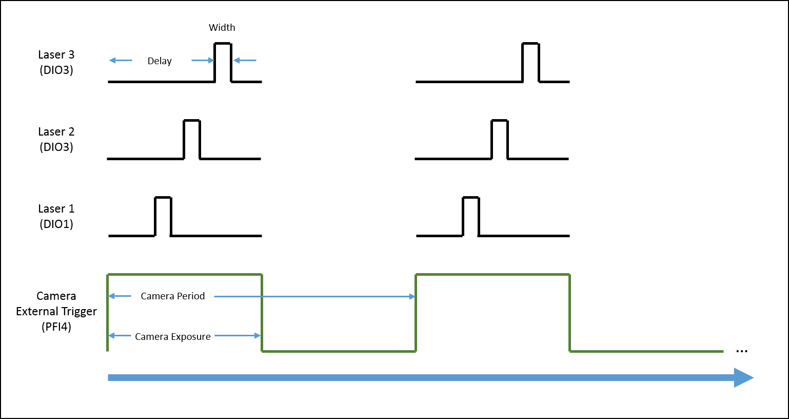
Generate a single pulse on several channels of an external trigger high-speed DIO
Hello
I'm trying to implement a system using a PCIe-6535 b connected to a high speed of SMB-2163 DIO. The system must be configured to work with a camera send a trigger (at the beginning of each show) to the PFI4 which in turn sends a single pulse on three digital output channels to lasers. Each output has its own specific deadline and the width. There is no counter on the SMB-2163, so I think I need to use Pulse Width Modulation (PWM). I saw this example and adapted to my system:
https://decibel.NI.com/content/docs/doc-8010
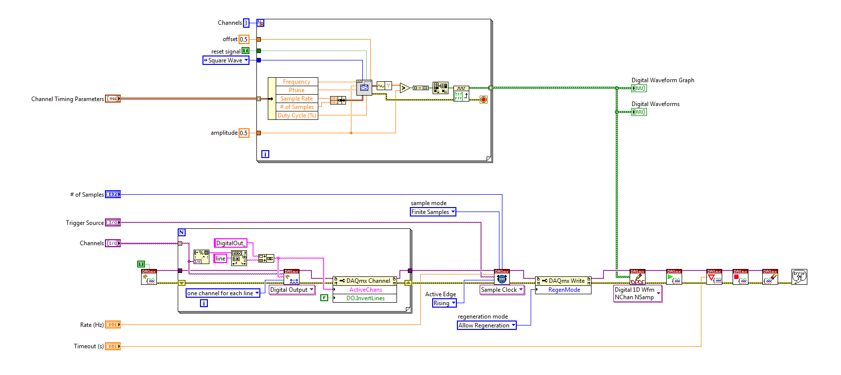
However, when the source to enter the DAQmx VI of sample clock is set to PFI4 (instead of the on-board clock) to receive input from the camera, changes in behaviour. The rate of sampling in the sample clock VI is ignored, and each element of the digital waveform is triggered. I need the sequence to complete each after trigger.
I am attaching a quick diagram of the sequence. Any suggestions on how I can get this kind of events triggered? (With the help of LabVIEW 2013)
Thank you
Mike
PLATES
The external signal must be configured as a trigger for digital startup rather than the sample clock. I do not think the 6535 redeclenchables supports digital output, so you don't have to restart the task after receipt of each trigger (something like this, however you can improve performance by committing to the task by using the task of control DAQmx before entering the loop).
Best regards
-
Samples of output by release, with all the preloaded samples
Hello
I was wondering if it was possible to (Using matlab and labview)
preloads all the samples on the acquisition of data, and each trigger card, it displays the following value (rather than all of them, which is the default setting)
IE load (0 5 9 7 2 6)
at each call, it changes the output to the next value. (and if possible a loop around)
I have managed to program on matlab, load the sample and then wait for trigger to display the value. However, I need to make one of the values at the same time and can not preload all values. It is causing serious time delay/cpu for my program.
Any help would be appreciated.
I use PCI6259
Hi Michael,
You could certainly write this in C (although labVIEW would be much faster), as for Matlab, I can't really comment on!
Please find attached 2009 version
Maybe you are looking for
-
EliteBook 8470p: HP Client Manager Security extension only appear only on the page Chrome plugin
So I have downloaded on my computer HP customer Security Manager, and all works fine. I downloaded the HP Client Security Manager for Chrome extension, but I can't allow it under chrome://plugins because it is not even appear there. I allowed him u
-
not supplied by windows 8 Messaging Instant messages in Skype
One of my friends uses instant messaging to windows 8. He was signed as a "non-visible". He sent a text to that me and I responded via Skype (version 6.3.0.105). No reply until what he asked me if I was there. Looked like my messages were not returne
-
Some strange problems with laptop Qosmio
I don't know it is a problem of Qosmio, but I'm fairly well known when it comes to computers and I've never heard of it before. Unfortunately, it is not my computer. They're my friends, so I'm on the phone with him. She has a Qosmio and she says she
-
Satellite Pro L670 - first boot disk error
Helloneed help. My laptop computer brandnew said by the first start 'disk error '. What is a HD failure or another problem.
-
Use of user defined function in mathscript containing a structure
Hi, I am a novice user of LabView MathScript module, I have the following problem when integrating my code MATLAB, LabView, for HMM: in my program, I tried to call a MATLAB called "mixgaussinit.m" user-defined function, it shows this error... "