Frame API NV12 AVFrame (FFmpeg) camera
I'm trying to use the camera API to stream video, but since it currently only writes to a file I'm trying to use the callback with the video viewfinder.
void vf_callback(camera_handle_t handle, camera_buffer_t* buf, void* arg)
Given that it only becomes a video image in NV12 (close enough to YUV420P? I think?) I'm trying to use FFmpeg to convert. I already wore FFmpeg and it works fine, but I can't seem to get the image to convert on one MPEG frame.
My question is, does anyone know how to code the video image of the reminder using FFmpeg?
What makes a dummy AVFrame which works well when the video file is created:
/* Y */ for(int y=0;yheight;y++) { for(int x=0;x width;x++) { picture->data[0][y * picture->linesize[0] + x] = x + y + a * 3; } } /* Cb and Cr */ for(int y=0;y height/2;y++) { for(int x=0;x width/2;x++) { picture->data[1][y * picture->linesize[1] + x] = 128 + y + a * 2; picture->data[2][y * picture->linesize[2] + x] = 64 + x + a * 5; } }
I found this in the FFmpeg source, but it does not quite work to convert the image:
int8_t *y, *u, *v;
y = picture->data[0];
u = picture->data[1];
v = picture->data[2];
const uint8_t *src=buf->framebuf;
for (int i = 0; i < (c->height + 1) >> 1; i++)
{
for (int j = 0; j < (c->width + 1) >> 1; j++)
{
u[j] = *src++ ^ 0x80;
v[j] = *src++ ^ 0x80;
y[2 * j] = *src++;
y[2 * j + 1] = *src++;
y[picture->linesize[0] + 2 * j] = *src++;
y[picture->linesize[0] + 2 * j + 1] = *src++;
}
y += 2 * picture->linesize[0];
u += picture->linesize[1];
v += picture->linesize[2];
}
Here is the reminder and any other test code:
void vf_callback(camera_handle_t handle, camera_buffer_t* buf, void* arg)
{
if (buf->frametype != CAMERA_FRAMETYPE_NV12)
{
return;
}
printf("got video buffer of size %d x %d, bytes: %d\n",
buf->framedesc.nv12.width, buf->framedesc.nv12.height,
(buf->framedesc.nv12.height + (buf->framedesc.nv12.height / 2))
* buf->framedesc.nv12.stride);
av_register_all();
video_encode_example(buf, "/accounts/1000/shared/camera/VID_TEST.mpg",
CODEC_ID_MPEG1VIDEO);
}
void video_encode_example(camera_buffer_t* buf, const char *filename,
enum CodecID codec_id)
{
AVCodec *codec;
AVCodecContext *c = NULL;
int out_size, outbuf_size;
FILE *f;
AVFrame *picture;
uint8_t *outbuf;
int had_output = 0;
printf("Encode video file %s\n", filename);
/* find the mpeg1 video encoder */
codec = avcodec_find_encoder(codec_id);
if (!codec)
{
fprintf(stderr, "codec not found\n");
exit(1);
}
c = avcodec_alloc_context3(codec);
picture = avcodec_alloc_frame();
/* put sample parameters */
c->bit_rate = 400000;
/* resolution must be a multiple of two */
// c->width = buf->framedesc.nv12.width;
// c->height = buf->framedesc.nv12.height;
c->width = 352;
c->height = 288;
/* frames per second */
c->time_base = (AVRational)
{ 1,25};
c->gop_size = 10; /* emit one intra frame every ten frames */
c->max_b_frames = 1;
c->pix_fmt = PIX_FMT_YUV420P;
// if(codec_id == CODEC_ID_H264)
// av_opt_set(c->priv_data, "preset", "slow", 0);
/* open it */
if (avcodec_open2(c, codec, NULL) < 0)
{
fprintf(stderr, "could not open codec\n");
exit(1);
}
f = fopen(filename, "wb");
if (!f)
{
fprintf(stderr, "could not open %s\n", filename);
exit(1);
}
/* alloc image and output buffer */
outbuf_size = 100000 + 12 * c->width * c->height;
outbuf = (uint8_t *) malloc(outbuf_size);
/* the image can be allocated by any means and av_image_alloc() is
* just the most convenient way if av_malloc() is to be used */
av_image_alloc(picture->data, picture->linesize, c->width, c->height,
c->pix_fmt, 1);
/* encode 1 second of video */
int a = 0;
for (; a < 15; a++)
{
// fflush(stdout);
/* Y */
for(int y=0;yheight;y++) {
    for(int x=0;xwidth;x++) {
        picture->data[0][y * picture->linesize[0] + x] = x + y + a * 3;
    }
}

/* Cb and Cr */
for(int y=0;yheight/2;y++) {
    for(int x=0;xwidth/2;x++) {
        picture->data[1][y * picture->linesize[1] + x] = 128 + y + a * 2;
        picture->data[2][y * picture->linesize[2] + x] = 64 + x + a * 5;
    }
}
// uint8_t *y, *u, *v;
// y = picture->data[0];
// u = picture->data[1];
// v = picture->data[2];
// const uint8_t *src=buf->framebuf;
//
// for (int i = 0; i < (c->height + 1) >> 1; i++)
// {
// for (int j = 0; j < (c->width + 1) >> 1; j++)
// {
// u[j] = *src++ ^ 0x80;
// v[j] = *src++ ^ 0x80;
// y[2 * j] = *src++;
// y[2 * j + 1] = *src++;
// y[picture->linesize[0] + 2 * j] = *src++;
// y[picture->linesize[0] + 2 * j + 1] = *src++;
// }
//
// y += 2 * picture->linesize[0];
// u += picture->linesize[1];
// v += picture->linesize[2];
// }
struct SwsContext* fooContext = sws_getContext(c->width, c->height,
PIX_FMT_YUV420P, c->width, c->height, PIX_FMT_RGB8,
SWS_FAST_BILINEAR, NULL, NULL, NULL);
AVFrame* outpic = avcodec_alloc_frame();
av_image_alloc(outpic->data, outpic->linesize, c->width, c->height,
PIX_FMT_RGB8, 1);
sws_scale(fooContext, picture->data, picture->linesize, 0, c->height,
outpic->data, outpic->linesize);
/* encode the image */
out_size = avcodec_encode_video(c, outbuf, outbuf_size, outpic);
had_output |= out_size;
printf("encoding frame %3d (size=%5d)\n", a, out_size);
fwrite(outbuf, 1, out_size, f);
}
/* get the delayed frames */
for (; out_size || !had_output; a++)
{
fflush(stdout);
out_size = avcodec_encode_video(c, outbuf, outbuf_size, NULL);
had_output |= out_size;
printf("write frame %3d (size=%5d)\n", a, out_size);
fwrite(outbuf, 1, out_size, f);
}
/* add sequence end code to have a real mpeg file */
outbuf[0] = 0x00;
outbuf[1] = 0x00;
outbuf[2] = 0x01;
outbuf[3] = 0xb7;
fwrite(outbuf, 1, 4, f);
fclose(f);
free(outbuf);
avcodec_close(c);
av_free(c);
av_free(picture->data[0]);
av_free(picture);
printf("\n");
}
I use this with sample HelloVideoCamera, so if you want to run it, you can plug the recall on that.
So I did a bit of preliminary inquiry and it seems that the following fields of the struct AVFrame interest a NV12-> YUV420P conversion:
uint8_t* data[];
uint8_t linesize[];
int width;
int height;
It seems that in the case of YUV420P, data [0] is a pointer to the pixel plan Y data [1] are a pointer to pixel map U and data [2] is a pointer to the plan V pixel.
You will notice that in the NV12 format, there are only 2 planes: a plan of Y and a plan combined UV. The trick in this conversion process will be out interlacing the you and values V of the UV combined plan separate from you and V aircraft.
The plan should be usable as - is. You shouldn't even need to copy the pixel data.
picture->data[0] = buf->framebuf;
picture->linesize[0] = buf->framedesc.nv12.stride;
The code above should be enough to put the plan in place Y. If you really want, you could malloc air pixel data [0] and then memcpy() the Y data buf-> framebuf (line-by-line!), but it's probably a waste of time. I noticed that you use av_image_alloc(), which you probably want to skip since you probably only want alloc data [1] and [2] data plans and will probably have to do it by hand... you can consider to implement a pool rather than return to malloc() in real-time.
In any case, once you have the data [1] and would have [2] data had malloc (), you should be able to make an of interleave and copy from you and data buffer V of NV12 as follows:
uint8_t* srcuv = &buf->framebuf[buf->framedesc.nv12.uv_offset]; uint8_t* destu = picture->data[1]; uint8_t* destv = picture->data[2]; picture->linesize[1] = buf->framedesc.nv12.width / 2;picture->linesize[2] = picture->linesize[1]; for (i=0; iframedesc.nv12.height/2; i++) { uint8_t* curuv = srcuv; for (j=0; i framedesc.nv12.width/2; j++) { *destu++ = *curuv++; *destv++ = *curuv++; } srcuv += buf->framedesc.nv12.stride; // uv_stride in later API versions }
Note I guess one of strides you and plan V is desirable. Then, if your allocator data [1] and [2] data plans with long strides, "Stride" pointers of dest as necessary at the end of the loop 'j '.
Now you should have a YUV420P frame that will be compatible with your encoder. Or at least that's how to interpret headers no matter what I was watching
See you soon,.
Sean
Tags: BlackBerry Developers
Similar Questions
-
sending of the U8 and SGL to the same message - frame API
Hello
I use the frame API and want to send a message that contains the following information
Length of the payload - 8 bytes (most likely)
byte 0 - cmd ID
byte 1 + 2 - ID of the unit
Byte 3 - selection
byte 4-7 - coefficient
I have the first 4 bytes to work because I take a string, converted to a byte array and insert each byte in the array of U8. The problem I am trying to solve is to be able to do the first 4 bytes of the U8 and the next 4 bytes hold the coefficient that is stored in a single-precision floating-point number. How can I configure write it a message from position 4 of the payload to correctly send the SGL coefficient? A SGL can be packed in 4-byte payload? I thought he could because 4 bytes = 32 bits and a SGL is a 32-bit number. I'm confused because the writing block takes a U8 array as input data.
Thank you
Gary
I realized everything I have to do is cast the array of bytes in a floating-point number in single precision.
-
Hello
I use a PXI-8461 to control 2 CAN bus lines.
When I run the bus monitor to the MAX, both work correctly (frames are coming).
But I lost a day now to try to make the two lines operate in my application.
I call ncConfigCANNet.vi and ncOpen first with CAN0, then with CAN1. ncOpen with CAN0 gives me an objHandle, but when I ncOpen cann with CAN1 after that, I get objHandle = 0 but no error!
(I do not use error entries)
So in my application CAN0 is running, CAN1 finally returns an error when I try to read using the objHandle (s is 0).
I even tried to use the example of NEITHER "Multiples CAN Frame API maps unique DAQmx map Input.vi" with the same effect.
Is there a known issue with this subject?
I use
NI-CAN 2.7.2f2
LV 8.5.1
PXI8461 with CAN0 and CAN1 working with the MAX busmonitor
100g Ritter Sport chocolate / hour

Sorry, my fault.
I was able to solve the problem. My length of read - and write-queue was too big. I was using 100 for each queue. This works for a CAN interface, but not for 2. And, Yes, there is an error message... I lost this error somewhere in the error handling.
Something beautiful that I used for the first time here is the network debug function for the executable files. Really cool and useful.
Detective Conan!
-
Problem with sending of master header with XNET API instead of CAN frame API
Hi nice guys.
I am using the XNET API to switch Master slave with LIN Protocol task. Since I have no prior experience, there is something problem as the Interface of the NI USB-8476 s cannot be detected. Gifts of windows prompted the following information:
Error-1074384758 is produced in .vi:1 XNET create Session (single-point output Signal)
Possible reasons:
NOR-XNET: (Hex 0xBFF6308A) the name of the interface does not specify a valid and existing interface. Solution: Use a valid and existing interface. These can be obtained by using MAX, XNET properties of the system, or the name of LabVIEW XNET Interface IO. If you use CompactRIO, see the topic "Getting started with CompactRIO" in aid of software and hardware OR XNET.
but in the MAX of NOR, the device is detected as "LIN0. Even control interface entry in the examples NOR displays the error. But if I take the CAN API of frame, it works well.
Does anyone have an idea. I'm so appreciate. Tanks in advance.
Best regards
Melo
Dummy me, know that the XNET API still do not support the NI USB-8476 s, which I am applying.
Kind of hard to use the API NEITHER of MAY to get the feature I need, that seems easy to get with the XNET API.
Problem solved!
-
How to detect the red frame in a series of images using the webcam?
Hey, I'm a new use lab view(8.2_n_8.6).kindly ca any1 help out me in the detection of the color red in a series of frames being taken by a usb web cam.i have done the striking thing but don't know what to do now.plz help out me. Basically, I have to do the following:
(1) the camera continually does video
(2) at the time of what a red or red frame color comes through the camera, the camera is programmed, such that she will grab this red box. and display the captured image
Please hep me out.i need serious help.
I enclose a vi that is striking images and then the info n thn displyaing color red xtracting his lines intensities and wise coumn on a graph.here, I used a Gaussian surface to locate the color red.
-
Hello
I develop an application that communicates with a microcontroller. I would like to use the API to frame for a setup where I can send commands and get the answers and want to use the API channel for a mode where I'm simply followed the messages I get from the microphone.
I have a state machine where I starts with the opening of the frame API, have some different States I'll in that use the appearance of the request/response of the API framework, then a State that closes to the API of frame and opens the Channel API. The problem I encounter occurs when I already closed the frame API and began playing with the API channel work. When I click the monitoring button stop, I leave the while loop, who read a message defined in the DB can (havn't had in fact he still read the data) and run the Clear.VI Channel API CAN I get the following error.
Error - 1074388720 CAN Initialize.vi
Possible reasons:
NI-CAN (Hex 0xBFF62110) you can use the frame API and Channel API simultaneously on the same interface (for example CAN0). MAX tools use the channel API. Soultuon: Use a different interface with each API.
I need a way to get around this and I'm not sure why the raster API is not pretending to be closed, especially since I was a State in my state machine to close the frame API before you start using the channel API.
If anyone has any suggestions please let me know.
Thank you
Gary

It is more a question LabVIEW but because its you, here's an example that lets you switch back and exit if you set the output check.
DirkW
-
It's more of a behind the scenes in question rather than coding. Let me give an Installer before asking. I use IMAQdx to a gige camera. I use a capture card in a while loop and process the images, the details don't really matter. Total time to do all the processing is about 200 MS, but I'm running the camera at 30 fps. Here the question arises. Clearly, my process is not running at 30 frames per second, but the camera is. Is labview buffering caught executives and then treat all, or will it do its process and catch the most common once it passes to the next iteration. I think the later is the case, and that's what I want, I just wanted to ask an expert to get what is happening behind the scenes. THX.
Matt
Hi Matt!
You belief is correct. With the Acquisition of capture, a buffer is used and is crushed. You can try an acquisition of the sequence, which uses the number of buffers defined by the user. Take a look in the help file IMAQdx, too. (Start > programs > National Instruments > Vision > Documentation > IMAQdx). There is a title page examples of programming low level function that has a very good overview of the functioning of Snap, Grab and Acquisition of the sequence. (I just searched 'sequence'). I hope this helps!
Kristen H.
-
invoking the application/Gallery bb10 webworks app camera app
Hello
in my application that is based on its targeted and webworks for Blackberry10 OS, how to invoke enforcement camera and Gallery.
can I somehow call it using blackberry.invoke.invoke api pointing to the camera or a gallery, please let me know.
You can use the invoke of verification on the next page for more details:
-Camera: https://developer.blackberry.com/html5/documentation/camera.html
-Gallery: it's a little more complicated, but you can usually call it through the target of the application as follows:
-action: 'bb.action.OPEN', target: 'sys.pictures.app '.
If you wish, you can use the card for the camera as defined here:
- blackberry.invoke.card.invokeCamera
- https://developer.blackberry.com/html5/apis/blackberry.invoke.card.html
-
Why is my CTI in the middle of a frame?
In my maincomp, the gray area around the CT is divided, but in other compositions, it starts at the ICT and is moving forward. IM weird problems with 3D layers, move to the wrong camera frame before or after another camera is selected. IM also getting an error I've never had before.


Take a close look at your ITCS. It is exactly on the mark of the image. What you see is the shutter phase. You who set composition settings in the Advanced tab. This is visible only if you have activated motion blur. Check out these screenshots. It's actually an important indicator of how blur will work especially when you try to match the blur on the images with the blur of movement on the graphics. The width of the line grey watch the shutter angle, the position you shows the phase or when the shutter opens in what concerns the time.
180 ° and - 90 ° is the default and that looks like what you see.

180 ° to 0 ° gives you this view.

at the - 90º 720º looks like this. You will notice that the blur begins half-way before the next image, but spans 2 complete images.

It's a little hard to explain without a video tutorial, but what you want to do with shutter Angle and shutter Phase is that the movement of your graphics card with the motion blur in images. Say someone swinging a baseball bat. On the first image where there is motion blur, you can set your shutter phase and angle so that your chart is the same blur on its first image of the movement and the last. It is where the phase. The amount of blur is set in correspondence with the shutter Angle. This may be different for each shot. This is what is happening here. There is nothing wrong with the settings of your model, and is not a bug. It has nothing to do with the problems of 3D layer.
Here's the view with the off motion blur:

-
Why the debth bit of my different raw file image in my camera, Brigde and the opening in Photoshop?
I have a full frame Nikon D700 12 megapixel camera that has a depth of 12 to 14 bits. I used to shoot images with the file format raw Nikon (NEF) with the parameter of color space to Adobe RGB (1998). When I select a picture to view the details of the metadata in Adobe Bridge, the number of bits is indicated as 16 and color as RGB. Open the image in Photoshop displays the detail long and narrow line down the near the bottom of the screen. It indicates that the color is 8 bits but still Adobe RGB (1998).
Can someone explain please these fluctuations? It's always a NEF file, I want to talk to.
Thank you.
With Camera Raw open, you must set the color space and depth of Bit to open like in Photoshop. See image:

Edit: In addition, a raw file contains raw data - no color profile embedded. At least is not all programs, with the exception of Nikon, will recognize.
Benjamin
-
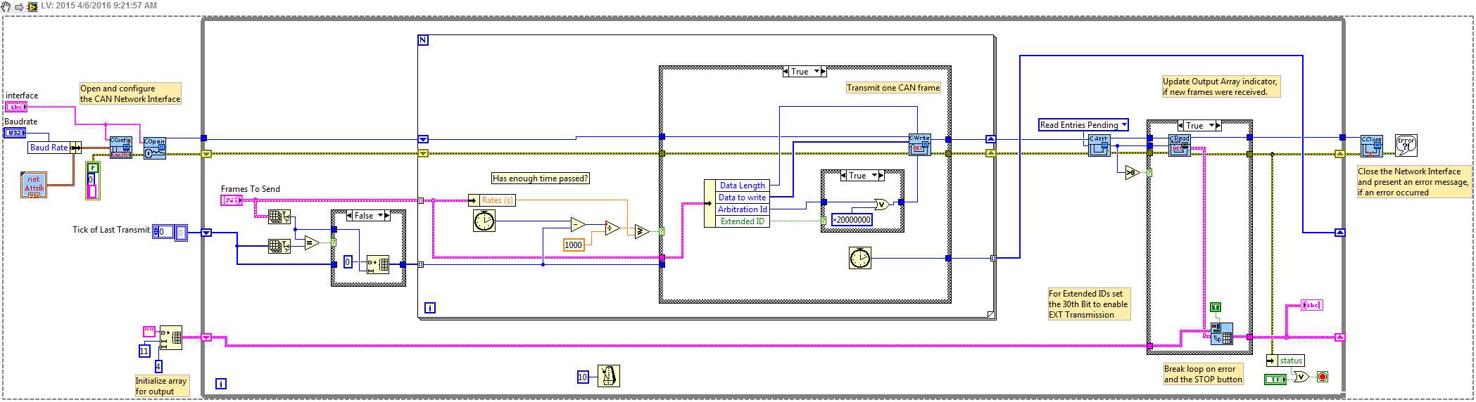
Is it possible to send several messages with IDS of different arbitration periodically (messages can have different periods) by simple CAN interface?
I use CAN frame API 2.7.5.
Not any material support retransmit material timed, so I usually stick with software programmed if calendar is not super critical. An improved version that works with an array of broadcast signals is attached. Each rate is assessed at the same time, and then this frame is sent, if enough time has passed.
-
Is it possible to change the default length (13 bits) of the FLAX of Break with a NI USB-8476 and the NI-CAN frame API ?
I'm sure that it is supported, but may not be documented. Try the 0 attribute x 80020047. He must accept the same range as the version of NOR-XNET.
-
I have two boxes CAN1 and CAN0 hooked to a junction box
1 ea, CAN Breakout Box - Junction 14-Port with power and termination box
2 bis, NI USB-8473 -1-Port high-speed CAN, USB Interface
I have LavView 2013 worm 13.0f2 (32 bit)
I use 'c' library: C:\Program Files (x 86) \National Instruments\NI - CAN\MS Visual C\nicanmsc.lib
who has a 'creation Date' 13/03/2012-15:35
I think the 2.7.4 version number but I don't know where to find this number.
I have Windows 7I want to send a J1939 Messages on CAN1 with LabView
(I have a job.)I would like to receive Messages from the j1939 on CAN0 using MS .c program
(I have work for BAM messages, but not for RTS/CTS messages
< 240="">I can't get non-BAM RTS CTS messages to work.
I get the RTS, but I don't know how to set up a BOX to be associated
'BB' DA (Destination address).
I also send the CTS with ncWrite but I always get a
"Connection Abort is.I think I need to configure the two cans with an address.
I wish
CAN1 sending CAN be 'AA' (it would also receive the message CTS)
and
CAN0 reception CAN be 'BB' (this would also send the message CTS)Here's what I'm trying:
I am trying to send a message of J1939 RTS CAN1:
1CC2BBAA
where
1 - 0001 1100
PAPP DETERIORATED
aaOr rrDP
ddFi IPI
7 -low priority
. -SOF will have the value 1 in the LabView by ORing program 0x20000000.. C2 -194 - PF
Group of settings label: report of Performance Monitor
PGN Desc. :
Specify the legislative requirements of OBD
manufacturers must control all emissions and
SELF-DIAGNOSIS of the components system throughout to wait
life of the vehicle..... BB -187 - PS / DA
A 'BB' address I did up to destination.
I would like to CAN0 be configured with this address
but I don't know how I should do this?...... AA -170 - SA
A source address 'AA' I did.
I wish that CAN1 be configured with this address
but I don't know how I should do this?I put in place of the test data
| LS MS | LS MS | LSD MSD | LS MS | LS MS |
| F4 01 | 0A 00 | 8 D F8 02 | 14 00 | 0A 00 |who is for
----------- ------- ----------------------------------------------
SPN
Position
in
PGN SPN SPN Description
----------- ------- ----------------------------------------------
01-02 3048 engine cycles counter
03-04 3049 control of the Conditions encountered
05-06, 7.6 3066 SPN of the Applicable System Monitor
08-09 3067 numerator applicable system monitor
10-11 3068 denominator applicable system monitor
----------- ------- ----------------------------------------------If you reverse the LSD and the MSD around you get this:
(I just do these numbers for testing.)| LS MS | MS LS | MSD LSD | MS LS | MS LS |
| F4 01 | 0A 00 | F8 02 8 D | 00 14 | 0A 00 |01 F4 -online 500
Engine ignition cycles counter0a 00 => 10
Terms of OBD monitoring
Met
F8 8 02
1111 1000 0000 0010 1000 1101
.... . 000 0000 0010 1000 1101 "."-unused bits set to 1
0 0 0 2 8 D
00028D -online 653
SPN of the Applicable System Monitor
Injector cylinder #03
00 14 => 20
Applicable system monitor
Numerator
0a 00 => 10
Applicable system monitor
DenominatorI used the example LabView .vi at the following address to send the message:
http://www.NI.com/example/31215/en/
Then click on the link to the right "J1939 Transport Protocol"
That you will get this zip file: "transport_protocol_8.6_2v.zip".Inside of this zip file
«...\transport_protocol_8.6_v1.1\transport_protocol_8.6\J1939 Multi Frame\Examples\NI packet CAN fit OR Example\J1939 CAN fit Example.vi"This load in LabView
I used the following example of 'C' to read the message:
C:\Users\Public\Documents\National Instruments\NI-CAN\Examples\MS Visual C\Frame API examples\CAN Receive\CAN Receive.cI wrote a 'c' code to test the RTS message
and then
do a ncWrite to send a CTS.
He doesn't work and I get "Connection Abort Message"I don't know what I'm doing wrong.
Here is the output of debugging with my comments (CMT :)
-------------------------------------------------------------------
CMT: EC message with 0 x 02000000 ORed SOF in LabVIEW
CMT: and the priority changed shape 05:53 (110)
CMT: do 38
CMT: 0011 1000
CMT: PAPP DETERIORATED
CMT: aaOr rrDP
CMT: ddFi IPI
CMT: 1 priority 10-6CMT: EC - Transport Protocol - connection Mgmt.
CMT: BB - DA (Destination address)
CMT: AA - SA (Source address)SAM: 10-16, RTS Message
CMT: 0 b 00-11 my size
CMT: 02 NumPackets
CMT: MaxNumPackets FF-255
CMT:-00C2BB PGN BB C2 00
CMT:
CMT:
CMT:c 10:32:51.548 38ECBBAA CAN data frame C2 of BB FF 02 00 00 0b 08:10
iMessageDataSize =: 0:
RTS beginning: 10: (10 - RTS)
RTS my size: 000 b: (11)
RTS Num Pack: 02: (2)
RTS Max Num Pack: FF: (255)
RTS PGN: 00C2BB:CMT: Here's the CTS to send the data that I created to send with ncWrite
CMT: 11 - fixed 17, message EC PGN 60416
CMT: 02 - maximum number of packets that can be sent
CMT: 01 - next to use sequence number
CMT: FF FF - reserved. Filled with FFs
CMT: BB C2 00 - 00C2BB PGN.... In SendCTS...
iBAMRTSCAMPgn =: 00C2BB:/Ucdata CTS [0] =: 11:
CTS /ucdata [1] =: 02:
CTS /ucdata [2] =: 01:
CTS /ucdata [3] =: FF:
CTS /ucdata [4] =: FF:
CTS /ucdata [5] =: BB:
CTS /ucdata [6] =: C2:
CTS /ucdata [7] =: 00:ActualDataSize =: 1:
CMT: I have more a data message "EB00" or "38EBBBAA" but I
CMT: get '38ECBBAA' with 'FF' in the 1 byte of data, which means
CMT: "Connection Abort Message.iPri =: 6:
iEdpDp =: 0:
iPf =: EC:
iPs =: BB:
iGe =: 00:
Fnpi =: EC00:
iSa =: AA:
c 10:32:52.799 38ECBBAA CAN data frame 8: FF FF FF FF FF BB C2 00
iMessageDataSize =: 0:I've corrected the program.
It was the following statement:
was as follows:
Status =
() ncWrite
gNetIntfObjhRx,
oCFSend.DataLength,
(void *) & oCFSend
);should be this:
Status =
() ncWrite
gNetIntfObjhRx,
sizeof (oCFSend),
(void *) & oCFSend
); -
Message data CAN be read with more 64-bit
Dear all,
I work with CAN PCI card series 2 with Labview 8.2.1 measurement and automation 5.1.
I do the measures since an ECU.
This one (please see piture) comprises more than 64 bits for one ID.
I cannot find how I can read these data using 'Channel API'. Is this possible?
On MAX, I am not able creat CAN measure with more than 64-bit task...
It is necessary to use only "frame APIs.
Thanks for repply.
Concerning
NI-Channel CAN API is not able to deal with Multi part messages, so you must use the NI-CAN frame API to read the Multi part message and do the conversion to physical quantities on your own.
-
I was playing around with the new NI XNET drivers read CAN data and I need some experts advise on this topic. In the frame API, I remember to be able to check that if there is data on the queue of read before reading, with Xnet, I have not found this option. XNET use playback function that will read the entire queue without worrying if the data is present.
This causes me a problem, because I'm constantly calling loop playback function, the data are written to a table of images, then the table will be empty for the next iteration because the reading queue was empty during the second reading.
How can I continually read data from the queue of reading without accidental my output table?
I tried the survey/Deque method, but it works well for me. Is someone can you please tell me what is the best practice for continuously reading the CAN data and treatment using drivers XNET?
Thank you
Sam
Looks like you want to use with your berries shift registers. Discover this Subvi, which is part of the expedition OR XNET examples. You can find examples from the Finder example under help > find examples.
Apart from converting it the image into a string, the additions loop the string to an array and use the shift registers to pass the array in the iterations of the loop.
Is that what you're looking for?


Maybe you are looking for
-
Hello I have already ordered through HP backup diskettes and tried to recover my installation of Windows 7 by using the provided disks. Before this attempt at recovery facility, tried to use several iterations of Linux, so I formatted my HARD drive a
-
Java has more than 24 hours to install and always current
I have a new HP Pavilion dv6-7028TX laptop. There is no java at all on this subject. So so I'm trying to download and install without success. If anyone has had this problem and what can I do to fix this? It took more than 24 hours to install and th
-
Who are my tech gurus? Are what they BONE fide Microsoft personal assistance?
Is these guys real teams of Microsoft support?
-
Dell order and integration Suite for System Center Configuration manager 4.0
Hello I just installed the Dell order and SCCM integration suite. When you try to import a driver cab file to create a driver package, I get an error saying that the software could not recover present distribution points in the server. I tried to ins
-
Connecting to homegroup shows old computer name
Original title: can not change the name of the computer I have 2 computers: OFFICE-DANA and DANA-PORTABLE. When I try to set up a homegroup, the office returns with "DANA-PC you asked to join the homegroup." I do this on my DESKTOP that is DANA-DES