Frequency-wave number domain
I would like to turn my non-stationary ground penetration radar and the seismic signals from the time domain to the frequency-wave number domain in my LabVIEW 7.1. The goal is that later f-k/Stolt migration. But I have found no useful VI in LabVIEW. Y at - it all?
Thank you.
Wallace
Greetings Wallace.
Unfortunately, to my knowledge there is no integrated inherent method of LabVIEW to perform this operation. While we have another screw for the conversion of area, such as the field of simple time in the frequency domain, etc., this seems to be outside the scope of what the development system and tool boxes offer at present. If you think it would be a good feature to include in LabVIEW, please feel free to create a product suggestion to www.ni.com/ideas.
Kind regards
Michael G
Tags: NI Software
Similar Questions
-
What is the relationship with the sampling frequency and number of samples per channel?
In my world, if I wanted to taste 10 seconds 10 Hz (100 s/ch), specify a rate of 10 and a number of samples of 100. This would take 10 seconds to return data. The task does not appear to behave this way. No matter what rate and the number of samples, I chose, I spammed with data at 1 Hz or more.
What I am doing wrong?
This problem is resolved by making a request for telephone assistance. It turns out that the minimum sampling frequency of the NI 9239 is 14xx s/s. I don't know why there is a minimum sampling frequency, but now I have to go to the next question discussed at this link:
-
Wave number o obtenho da licença meu produto?
OLA fiz a compra creative cloud, very baixa only pelo has Avaliação versão. Gay o registro number, mas em nenhum momento ELE me repassado of faith. Como FACO para o código resgatar?
Hello
If you need help to use the code,
Reference:-help code them redemption
After Redeemer code try disconnecting favoured compared to the creative clouds:-https://helpx.adobe.com/creative-cloud/help/sign-in-out-activate-apps.html
In case you continue to get an error for the trial, visit:-https://helpx.adobe.com/manage-account-membership/cc-reverts-to-trial.html
-
determination of the sampling rate and the frequency waveform data record
Hello
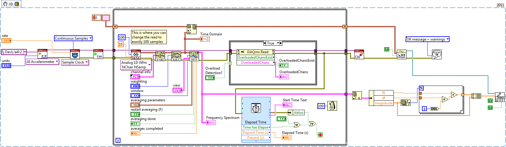
I write a simple program that collect data from a triaxial accelerometer input, convert it to a frequency spectrum, and then save the time domain and the frequency of the waveforms in an external file separated. I don't understand how to set the sampling frequency, however. On the DAQ Assistant, I updated the acquisition mode "Samples continues" and read samples is 2 k, which corresponds to the total number of data points that are collected. How can I program sampling for awhile, it 30 seconds, for example? Wouldn't be better to set up a trigger, as it will continue to collect data up to what I told it to stop?
I also want to save waveform data in a separate file that can be easily seen by other computers that have not installed Labview. I have currently the program put in place to convert a text string of the waveform of the time domain and then save it in a text file or a spreadsheet. It works fine, but I would also like to record the frequency wave, which is a different type of data. How can I do this or is there a better way?
My program is attached. Thanks for your help!
Here's how you can use the shift register to build the table, and also where you can choose to play exactly 100 samples per while the loop iteration.
Brian
-
error: the number of sample must be > 0 Please help.
Dear genius.
I tried the same mistake in this forum, but I do not understand how I can solve my problem.
I'm just a beginner in LV, so I need your help. I made AM modulation and demodulation vi.
When I used 'fake signal' as signal message, noting happened.
but, I changed the signal simulated as 'acquire sound' and adds a waveform to play after that, there is problem.
in fact, I don't understand on the sampling frequency of number or a sampler.
How can I solve my problem?
and you know some site use digital communication with usrp and labview to try?
Please let me know your idea.
Thank you very much.
It seems that your alignment of waveform leave you with empty waveforms. You could just get rid of it. Just make sure that the number of samples generated in your carrier is identical to the one generated by your acquisition of the sound wave.
-
Hello
I have a problem of small labview.
I want to generate a sinusoidal pulse with labview and send it to a pc oscilloscope using my sound card.
I did first VI creates a sine wave and sends it to the pc oscilloscope. Works perfectly.
But now I want to create a sine wave with a single period (second VI). Problem is while the VI blocks if I want a high frequency (I need 10 kHz)
So the VI operates on frequencies low but gives this error with a higher frequency:
"the audio driver or the card does not support the desired operation."
Can someone give a solution for my second VI (creation of sinus with a period on 10 kHz). ?
Thanks in advance!
Jelle
Hello Benje,
The problem / the difference you see is indeed in coding and also in the sound card.
In the example of 'work' you use the VI of Signal to simulate with the following parameters:
-44100 samples per second (sampling frequency)
-Number of samples 10000 (samples per cycle of generation)
In the non-functional example, you specify:
- sampling rate = 1000 * 'Value of frequency control'. This info of sampling should be fixed (for example) to 441000 Hz.
-Number of samples 1000 (samples per cycle of generation)
As a sidenote:
Is there a reason why you used different functions to generate similar signals in the VI 2?
-
I have a system with a map of the 9234 compactDAQ 4 Groove and a 9401 in slot 5.
I use a function generator to create a 5V square wave frequency sweep.
The frequency of scans from 1 Hz to 10 Hz in 3 seconds.
I have this tee in my door to counter 0 (PFI1 - 16 Pin) and an analog input channel 0.
In LabView, I do a period measure counter that has a trigger defined on the trigger to start ArmStart HAVE.
Piecemeal the signal into two channels, I see the time counter correspond to zero-level positive slope crossings in the data to HAVE it.
By the presence of a square with a mutation frequency wave, I know for sure that the time is not out of a period.
I noticed the downturn to take samples, the greatest moment of the synchronization error.
Here is the data that I have saved:
sampling rate 1 / (sync error times)
51200 1250
25600 625
10240 256
2048 51.8
1651 37
It worked of Y = 0,0244 X + 1.1262 with R ^ 2 = 1.0
So it could be, I have a programming error, or that there is a bug in the hardware or the base software.
Thanks for any help to understand this question.
BTW, I use this system to make an analysis program in the stopped vehicle with direct sequence over time - of course analysis based on the revolutions. I found that order analytical tools was not flexible enough for what I had done, so I started from the ground upward.
Hi Greg,.
Looks like you see the entry delay the NI 9234 (Group delay). As specified in the instructions for use NI 9234, entry delay is equal to 38.4 / fs + 3.2us. This is because of how the sigma delta ADC works - after the start, it must acquire a certain number of samples before returning the first valid sample. This delay is expected.
Here is a knowledge base on the subject. There are a lot more, just do a search of the knowledge base for "group delay.
-
Generate digital waveforms of high frequency
Hi all
I have some problems. Today, I am generating several digital high frequency waves with my DAQ (PCI-6251) card. The duty cycle of the waveform must be adjustable.
The required frequency is 100 kHz.
To do this, I have tried several solutions:
(1) I used counters in the acquisition of data to generate waveforms, and it worked fine. However, I have only two counters. In my application, I need to at least three waveforms with different cyclical report;
(2) I used a 'loop' and structures 'case' in labview to build the model of waveform and then feed them to the digital I/o. However, the problem with this solution is that the frequency of the wave generated cannot be high.
(3) I used a 'digital' generator in Labview to generate waveforms and then feed them to the digital I/o. In this case, the time base is from an external source (200 kHz). However, with this solution, the cycle is not adjustable.
Please give me some advice on how to make these waveforms. Your assistance is appreciated.
OK, so I may be wrong, but after mucking around for a bit, I realized that the regeneration should be automatic - in other words, if you a pattern to the right and then just leave your VI work in a while loop, you will find that the generation is continuous. Discover the correlation dig write metered in the finder for example Labview. You can leverage this as you get the cyclical report you are looking for. You can split the signal down what you write a single period consisting of a series of 0 and 1. In other words, if you want a wave of 100 kHz with a cycle of 20%, you write a pattern of digital waveforms a 1100000000 at the rate of 1 MHz. Using this technique, the resolution of the cycle will be limited by the on-board clock speed (80 MHz = 0.125%).
Let me know if this makes sense - I am unable to reproduce this on my desktop and have never had to do this before.
Cheers, Matt
-
Sampling frequency of adjustment for the analog output of sine
Hello
I tried to do something very simple: using an analog output card PCI 6221 to produce a frequency 50 Hz sine curve. For this I used a Vi to create a curve sinus and different screws DAQmx. But I have trouble understanding the principle of virtual channel and I think I do an error of adjustment of the sampling frequency and number of samples: once for the vi, second time sine "DAQmx - synchronization. Can I use the same values for both of these screws?
On my oscilloscope, with frequency = 50 Hz and the sampling frequency = 1 kHz, I get a null signal. Then according to two values, I'm differently evaluated signals. For example, with f = 1 Hz and sr = 10 kHz, a frequency 0.7 Hz sinus.
Make sure that the start for the analog input task occurs after the analog output. By plugging in the wrong thread to an analogue output start task first, and then to the start task, you guarantee that the AI cannot start until after the startup of the AO.
-
Distortion after you convert the wav to mp3 file
Hello
I work with a sampling frequency .wav file 8 k, 16-bit, mono a Skype conference call that was recorded by the computer. Wav is ACM Microsoft file: Microsoft ADPCM. The audio quality of the original is not optimal, as you can imagine, but when I do my changes and convert to mp3 that sounds horrible. I don't know the technical term for it, but it sounds muffled and distorted - the effect you get when cut you your hand in front of the mouth and the move while speaking. I am at a loss for what to do. Is there a setting I need to change before conversion? I know it's a sampling rate low (I usually work with 44.1 K), which would contribute to the problem?
Any help is greatly appreciated!
Thank you.
In a quick test, I was able to get significantly better results with an 8K, 16-bit source conversion to MP3 when you change the MP3 setting to 16 kHz. In the file > save as dialogue, after selecting the MP3, click on the button 'Edit' next to 'Type of sample' and change the sampling frequency. The file size was virtually unchanged, but the audio quality has been increased and by looking at the two files in spectral view showed a marked improvement.
Edit: Oops, I answered by e-mail and didn't know that this has been posted on the forum Audition 3. I suspect the results will be even better with the 3 MP3 encoder - both are by Fraunhofer. Here were the differences I've seen when writing 8 k 16 K vs. The resulting file is 29KO in both cases.

MP3 recorded to 8K sampling frequency setting
-------------------------------------------------------

MP3 recorded at 16K sample rate setting.
-
Hello NOR community,
I'm new to LabView and was hoping someone might be able to help with a question I have. Currently, I use a data acquisition unit to sample external sine and I would like to change this signal by adding another signal that I could control using the front panel. Whenever I try just connect entry with something like the waveform sinusoidal vi and put a subtraction sign between them it doesn't work (I get an empty waveform graph). To work around this problem, I've resorted to a signal (via an analog output) and followed by reading the signal to data acquisition, and then finally I add the two together. It works this way, but he wastes two channels and I imagine that there is a better way. I enclose my VI, and I have marked the location of interest "where signals get subtracted ', which is currently displayed using two entries.
Thank you
Leo
You must ensure that your sampling frequency and number of samples is the same. It seems that your sample (with default values) rate is the same (1 kHz), but your number of samples is different (100 to 1000 the acquisition wave vs simulation).
-
Hi all
I use a PCI 6503 with a Gecko g320 servo controller. I have control of the engine, except that it is not precise enough. The attached vi is used to send a signal to the controller, which moves the engine. I would like to be able to specify the number of pulses of square waves, the duration of the pulse and frequency in addition to what I have. So a signal that would be long, 400 Hz, with 200 specified cycles, 2 seconds should be 200 cycles, then 1.5 seconds of silence.
I can specify how many cycles I want by the number of samples, depending on the sampling frequency. Is there a simpler way, perhaps a few vi I missed which will display a number of periods at a given frequency, or is the method to control the number of samples, the only way?
Thanks and good luck,
Alek
Hi Alek,
Baji is correct because changing the number of samples is the only way to accomplish your task by using a card PCI-6503. Please note that because the 6503 only supports software synchronization, your timing, especially your frequency, will be inaccurate due to the non-determanistic 1 kHz Windows system clock.
However, if you want more precise control of your cycle of use, frequency and length of your caliber, I highly recommend using a plank of counters/timers as the PCI-6601 or 6602 PCI. With these cards, you will have the ability to set the duty cycle, frequency and number of pulses when you set up a counter pulse generation output task. The impulses that you generate from these boards to counter will be much more accurate than what you can get a static DIO Board, as the 6601 uses a 20 MHz time base, whereas the 6602 uses a time base of 80 MHz to implement the pulse train.
There are many examples on how to proceed in the finder OR example ("you can reach by clicking on Help" find examples). "" There are a whole series of examples on how to implement a pulse train finished using counters in the input output material & "DAQmx ' file generating digital impulses.
-Abram
-
Creation-> hearing: file names have been changed
Hello
I'm trying to return on an OMF for a feature film. I want to go over the hearing for this step.
Sending the draft directly to hearing seems to work, but somewhere in the process
the file names are changed: the name of each file gets a prefix "extract" - why?
E.g. BRDS40E1T1.wav-> BRDS40E1T2 extracted.wav
It is very for the sound engineer solutions. Is there a way to maintain the
original file names? I intend to return on a referenced OMF, if original file
name seem to be essential.
Thanks for the help.
See you soon
PS: also something odd: why hearing is writing new files, when I just let out a referenced OMF?
The suffix _extracted is actually added by Premiere Pro when he sends stuff to the hearing. Unfortunately, hearing has no control of this. The reason why the suffix is added because it creates a copy of the clip (and the underlying file) which is just adorned range of the clip around the length of the handle.
Regarding the hearing of new write files when a referenced OMF sending, he will try to avoid creating additional copies. OMF has restrictions on the characters that can be in the name of the file, the sampling frequency, the number of bits, how long is the file name and so on. So if there are things that do not match this criterion, it will create a new file.
You can test this by importing an OMF that embedded media in hearing. He extracted integrated media, and then write a new OMF with the media in reference to what has been extracted. Since we know that the file names and the rest of the OMF-legal, it should be able to just reference the file directly without a copy.
-
Using results of actual rate clock by error 'the specified resource is reserved.
Hello!
I use DAQmx 9.8, win10 x 64, NI 6221 emulated Council, labview 2012 32 bits.
I need to define the AO sample clock frequency, check the actual clock rate, calculation based on the new value of pulse rate and write it in the jury for the output. The code example is attached.
Everything is ok, when I use the command as a timing (as people used to do) during the installation of the task, but when I am trying to set the clock frequency, then number of samples I get "error-50103 that is reserved for the specified resource. The operation could not be performed as indicated. The error occurs after DAQmx Write.vi. I tried to use two calendar controls or a combination of timing and order property node timing with the same result.
Is that it has no idea how to solve this problem? Probably, there are some more convenient way to get real rates that I don't know.
I him have not tested yet on real hardware, emulated alone on board.
Finally, I dindn can't reveal the source of the prolem. It was certainly not related to the synchronisation screw. Just more simple configuration of analog output generated the same problem in this VI, but working without errors when copied to the new file.
Rewriting all of the project from zero contributed to y for remedy. Initially, I tried to change the existing program of someone else to change the generator stand-alone benchtop to DAC signal generation.
Now, everything's fine. Due to the software is not complicated it only takes a few hours to rewrite

-
Config problem and reading of AI
Hello
I have a problem when I use have config and read the structure.
I use Labview new v12.0 and chassis PXI-1042 NI6120 daq card.
If I use NI MAX, I can measure approximately 1 V (which is the minimum value for the sensor) or I can measure 1 V using the voltmeter.
(@ OR MAX, I have set up for voltage analog - NI 6120 - ai0 - 0/5V DC - 20 kHz sampling frequency and number of samples of 4 kHz)
When I use have config and read the structure, I can't measure 1V! Channel ai0 value is 0 a little.
Config and read the ai0 channel structure is attached.
You have an idea what the problem is when I use config and read the structure.
Best regards
Serdar
Two thoughts:
1 looks like to your acquisition is set to finished samples, then you're exciting the sensor before running the code? Or have you tried to change continuously, so you can change the voltage of the sensor the code runs?
2. you mention DC in your configuration of MAX, but your coupling in your "10045" code means coupling AC. Do you intend to use the current alternative or continuous? If you want DC, your value of coupling must be 10050 (or you need to create a constant off the coast of the entrance so that you get the enum rather than use a digital).
Hope that helps!
-Ryan_S


Maybe you are looking for
-
12.4 composer view breaks track #1 albums.
I finally found the sight of the composer... To see only the first track of some albums was severed in a unique tack album of it own. The tracks weren't like that before 12.4. It occurs under several composers. Suggestions for a way around this?
-
Hello I develop an application that I want to run on the normal systems and in real time using LabVIEW Proffesional Development System 2012 SP1 To control how the application interacts with the user, I created a class that defines the type of user in
-
V3-574-309U (aspire V 15) no boot device
I got my new laptop for 2 days. I use it and it froze and then turns off and now says no boot device. Can someone help me?
-
What is the minimum tablet OS version to choose the product releases section
What is the minimum OS tablet to choose the product free upload for a beta of Adobe AIR Playbook 2.0 SDK?
-
problem with the window "work stoppage by program and click here for an online solution.
When to start any program and then a msg of error that set the work stop Clik for the solution online