Generate digital waveforms of high frequency
Hi all
I have some problems. Today, I am generating several digital high frequency waves with my DAQ (PCI-6251) card. The duty cycle of the waveform must be adjustable.
The required frequency is 100 kHz.
To do this, I have tried several solutions:
(1) I used counters in the acquisition of data to generate waveforms, and it worked fine. However, I have only two counters. In my application, I need to at least three waveforms with different cyclical report;
(2) I used a 'loop' and structures 'case' in labview to build the model of waveform and then feed them to the digital I/o. However, the problem with this solution is that the frequency of the wave generated cannot be high.
(3) I used a 'digital' generator in Labview to generate waveforms and then feed them to the digital I/o. In this case, the time base is from an external source (200 kHz). However, with this solution, the cycle is not adjustable.
Please give me some advice on how to make these waveforms. Your assistance is appreciated.
OK, so I may be wrong, but after mucking around for a bit, I realized that the regeneration should be automatic - in other words, if you a pattern to the right and then just leave your VI work in a while loop, you will find that the generation is continuous. Discover the correlation dig write metered in the finder for example Labview. You can leverage this as you get the cyclical report you are looking for. You can split the signal down what you write a single period consisting of a series of 0 and 1. In other words, if you want a wave of 100 kHz with a cycle of 20%, you write a pattern of digital waveforms a 1100000000 at the rate of 1 MHz. Using this technique, the resolution of the cycle will be limited by the on-board clock speed (80 MHz = 0.125%).
Let me know if this makes sense - I am unable to reproduce this on my desktop and have never had to do this before.
Cheers, Matt
Tags: NI Hardware
Similar Questions
-
Hello
I'm working on a project that requires two outputs digital signals at different frequencies. Frequency of the phase 1 is about 1 kHz and is modulated on and off to a pace that will change during the execution of the program. Wave 2 passes from 1 kHz to about 6 kHz while needing to be pretty accurate to the tenth of a Hertz.
Initially, I tried to manage the simultaneous output of signals at different frequencies using a single task on a single 9477 daqmx in a cdaq-9174 chassis. As far as I know, the best way to get a specific frequency in a waveform output is to set the sampling frequency up to 2 times the frequency of the wave that is generated and generate a waveform that is given to each clock cycle. This works very well when it comes to a gesture, but I was unable to get the frequency of the modulated wave (wave 1) remains constant when the frequency of wave 2 modified or vice versa.
I have a few other modules lying around (another 9477, 9403 and 9476) and I thought I would try another task running on a separate module. I find myself receive error-50103 message if I add these modules to my cdaq chassis and run one of the waveforms of a task set to run on the add-on. Is there a way to bypass this error? I guess it would cause by running two digital output on the cdaq-9174 tasks at the same time, but it seems to me that this wouldn't be a problem with an additional module.
How can I have two outputs digital signals, running at the same time, maintaining their independent frequency frequency of the clock of the other sampling rate changes. In addition, because the wave 1 is enabled and disabled at a defined frequency, I use it to set the number of samples to write when you write a range of waveforms in the module (when generating these two waveforms on the same module).
I'm sorry if the explanation was difficult to understand. I've attached an example of error 50103 lifting. This isn't really a part of my project as a whole, but it is the easiest way to reproduce the error.
Thank you
Hi awol.
I have a follow up for you. You encounter the error because the cDAQ chassis has only a timing engine of. You will not be able to perform simultaneous tasks of the call by the hardware. Please see the following knowledge base: http://digital.ni.com/public.nsf/allkb/5E0B829E50ADE1BC86257AC50062B2D2
Mike
-
How to generate arbitrary waveforms FRO meter
Hello
I have a problem in the generation of the wave as shown in JPG below. Need to generate digital waveforms 2
1. with the help of counter0 - digital waveform will be with pulse 60 (58 - good pulsations and 2 empty pulse)
2. with the help of Freqout - digital waveforms should be to synchronize with a 40 pulse signal 2 signal should be high for then 5 impulses.
I tried model digital generation with Boolean 2D table convert to digital waveforms. But somehow, I couldn't have expected waveform.
If someone could help me in this problem.
Thanks in advance
Vijay
FREQ Out is not able to generate either of two waveforms - it can only generate continuous pulse trains. In fact, even one of the complete M-series meters would be unable to generate your "Signal 1" - you must use the 2nd meter to the signal from the door.
Supported boards of series X buffered output of the counter and could therefore be used to generate a waveform. You can use Freq Out yet, but the X series boards have also 4 full meters if this should be enough resources such as Freq Out is not necessary.
Best regards
-
Generate a digital waveform like memory on PXI cards
Hello
I'm looking for a way to send a large digital waveforms using a PXI digital signal generator. I saw DIO HS cards, but their memory is smaller than the files that I want to transfer. My understanding is that the PXI backplane bandwidth 132 MB/s. So, I shouldn't be able to stream a digital signal from the memory of the card that is slower than the CPU? For example, 50 Mbits / second (equivalent to only 6.25 MB/s)? However, I think I understand after reading their textbooks is that you cannot continuously transmitting a large waveform of the processor memory file, you must transfer the file to the memory of Council first and then transfer that out.
Does anyone know if there is a way to have a flow of digital signal generation card an arbitrarily large directly from memory to the processor of digital signals? Or, what is the fastest card of pxi digital signal generation that does not require the storage of Council first files?
Thank you
Isaac
Hello Isaac,.
Take a look at the following area developer.
NOR-HSDIO Stream from disk (generation) using Win32 file IO
Note that you will not be able to take full advantage of the maximum rate of update HSDIO devices, because the data must be transferred in a bus. Some other considerations are the width of the data as well as the HSDIO device you select, which may depend on other requirements not related to the size of file or waveform (for example the standard voltage or whether you need hardware compare). For more information, take a look at the developer following items area.
Data streaming of Architectures in the PXI systems
The use of National Instruments Logic Analyzer and generator of test patterns SolutionAdvanced features of e/s high-speed digital devices White Paper Series
-
static/digital waveform output and low frequency measurement of voltage - SMU-6358
Hello
1. I have an attached VI [digital_voltage_output] who must generate a logical true or false static state in the output of the device/port0/line1 Word to say. When the VI works I click the button several times, but nothing happens to the port0/lines1.
2 such a thing [digital_voltage_waveform_output_square] if I'm trying to generate a digital waveform to pin the same with the waveform generating VI. If I connect a waveform chart to the output of the generator function VI, then the chart will show me the good waveform I want, but still nothing is written to the text file.
3. I have read the manual for the X series cards, but it remains unclear for me a little how to things of the road in LV I have a measure of the frequency measurement VI low frequency that I downloaded. It offers me the ports for the supply frequency - ctr0, 1, 2, etc. As far as I'm concerned the PFI ports are responsible for these types of actions. How can I find out the LV that I want to connect say ctr0 and pfi0? »
I use LV 8.6.
Thank you
Kriváň
Hi Kriváň,
The problem you had with the choice of a specific digital line as a physical channel, is that the control that was previously used in this example was created for a data acquisition task that uses a whole port rather than a specific line. I was able to overcome this problem by removing the control and recreate. The control now gives you the option to choose the specific digital lines e.g. port0/PXI1Slot2/$line0.
I was also able to overcome the error of-200802 you mentioned. I was able to do this in a real constant of wiring at the entrance to auto-start the VI DAQmx writing then remove the DAQmx beginning the subsequent code VI. The modified code is attached.
I hope this helps.
Best regards
Christian Hartshorne
NIUK
-
How to control each channel of the signals emitted by the generator of digital waveforms?
Generator has digital waveforms of 8 channels. I need to generate two different signals for HSDIO. How to change and control two different ways? In addition, how to translate pinout of the PXI-6541 to channels? I need pin 1,3,29 and 31 control signal individually.
Thank you!!
You need to combine your personal data in a table. The digital waveforms is simply a numeric representation of the binary table. It always boils down to bit 0 of each element of the array will channel 0 (or the first string that you specify in creating dynamic channels). The next bit goes to the next channel. My last post is very clear. To display the table in binary, right-click on a table element, then select the display Format, then select binary. You can also right click on the element, select Visible, then select Radix Show to display the small b before the number. One last thing, in the display Format window, uncheck the box next to the minimum field width to use. Then set the digital just below zone 8. Then select Pad with zeros to the left in the box below.
You should not use waveforms up to what learn you more about how the HSDIO operates on the input data. It is not difficult to combine waveforms, but it is not as clear as it is using an array of U8, U16 or U32.
Trying to explain further. The first number to be written to the HSDIO will have this effect: Bit 0 (LSB) of the number is written to the first HSDIO string you specify. Bit 7 is on channel 8, you specify. If you specify no 8 channels, the bits download ignored. If wiring in a certain number will produce only a single bit on each channel. In other words, the number has already combines the bits of all channels that you specify. Combine you do nothing yourself. Return to my photo on my last post. By wiring in a table, you cause a binary model must be generated.
I hope that is more clear.
-
6722 to higher frequencies (about 3.125 kHz)
Hallo,
How can I control the PCI-6722 with higher frequencies about 3.125 kHz? Is it possible to use Labview? How? If it is not possible, how can I control the map to higher frequencies and visualize the information in Labview? I have not found a link to get manuals etc. that help. Links are welcome.
Thank you
Verena
The PCI-6722 does not support the entry of digital waveforms. It's digital lines are static (unbuffered), and every acquisition of waveform of them must be software controlled. Since modern multitasking operating systems are not deterministic, this translates into large amounts of jitter in when samples are collected. If you need good digital waveforms entry, you will need a different card. However, the 6722 has two counters/timers, so if the function you are trying to run is less their capabilities (for example to determine the frequency of a digital input signal), you should be fine. Let us know which task you want to accomplish and we can point you in the right direction.
-
Hi people,
I have a challenge I'd like to discuss with you and hope to have some ideas and maybe a solution.
I have a systems acquisition (DAQ) Multifunction National Instruments NOR-PCIe-6353 means X-Series!
I would like to generate and measure signals pulse width modulation .
DRIVER:
OUTPUT:
FREQ: 0, 1 Hz - 1 MHz
Duty: 1-99%
Change the setting on the fly
(This works very well and is implemented)
ENTRY:
FREQ: 0.1 Hz - 40 kHz
Duty: 1-99%
Method of measurement: period of semi / ContinuousSamples / AsyncCallback
Here, I have problems I am running only on an Intel Core 2 Duo CPU E8500 @ 3, 16GHz.
And I want to run 2 PWM_IN and PWM_OUT 2
Low frequency work fine!
0.1 Hz - 20 kHz
It is a loopback with
myCounterReader_1.BeginMemoryOptimizedReadMultiSampleDouble (2, myCallback_1, myPWM_IN_1, myPWM_IN_1_Data);
Data = myCounterReader_1.EndMemoryOptimizedReadMultiSampleDouble (ar, on myPWM_IN_1_Data_actualNumberOfSamplesRead);
A higher frequency do not work very well!
20-40 kHz
I get exception Code of State-200279:
Attempted to read samples that are no longer available. The requested sample was already available, but has since been replaced.
Increase in the size of buffer, most frequently the reading of data or by specifying a fixed number of samples to read instead of reading all available samples would correct the problem.
Property: Value of NationalInstruments.DAQmx.DaqStream.ReadRelativeToRequested:
NationalInstruments.DAQmx.ReadRelativeTo.CurrentReadPosition
Property: NationalInstruments.DAQmx.DaqStream.ReadOffsetRequested value: 0
Task name: NI1_PWM_IN_ctr0
State code:-200279
40 kHz, period is 25us = 12, 5 HighTime and 12, 5 LowTime 50% DutyCycle
This means that each 25us I get a reading of 2 samples the HighTime and the LowTime
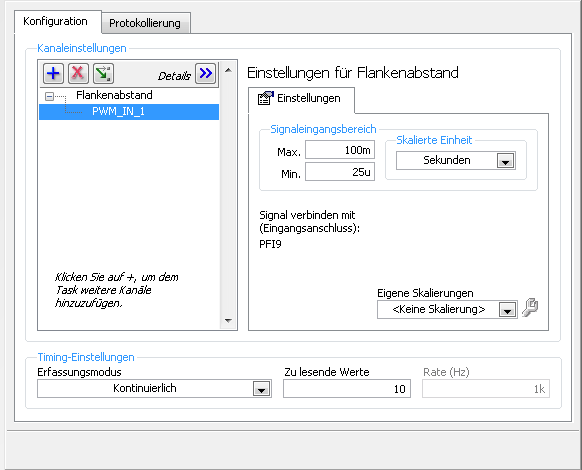
I charge my task of Max, so here's the Setup (sorry its german):
1 can someboby you explain to me what the MemoryOptimized?
2 Zu lesende values means that the size of the buffer 10 is not much but increases the size of the buffer to say 10,000 needing help on
a longer time!
3. playback of data more frequently is not possible because the data are under tension, because it is
4 specify a fixed number of samples I der number is HighTime 2 and LowTime
5. I have does not start and stop the task! Is it better to start and stop the task each time while I still may have a new buffer?
I hope someone has an idea for!
By
Steven
Reading with 50 software we period - bad idea, you will jump impulses. Try to use DAQmx Read Overwrite property, set it to "crush the unread samples" - it will overwrite the impulses without error.
-
Continuous output of digital waveforms on PCI-6602
I use 6602 PCI to get a continuous 1 MHz square wave output of DIO1 ~ 32 sequentially controlled by LabVIEW. I Ctr0 to generate a clock 2 MHz and used Ctr0InternalOutput as a source of sample for DIO1 clock ~ 32. I have attached the code and the texture as follows.
The code works fine on PCIe-6251 and digital waveforms of 1 MHz is very stable.
But when I run on PCI-6602 I got an error-200077 (you asked for: sample clock; you can request: on-demand).
6602 PCI does support material timing? I found no information about this its specifications. If she can't, how can I avoid this problem and get what I want? Thank you!
Yi
Version: LabVIEW 8.2
hardware: PCI-6602
Hello
Have you looked at the specification for the 6602?
http://sine.NI.com/NIPs/CDs/view/p/lang/en/NID/1123
Click on "specifications". Scroll down to "digital i/o". Watch "Timing". It clearly says "software".
The DIO lines on this Board are not timed by the hardware. They are clocked by the software. The data sheet that explains very clearly. That's why you see the error clock sample - that the Council can't stand DIO clocked by the hardware.
The 6251 supports clocked by DIO material, so why your code works very well with this Council. You can do the generation of signals with a 6602.
Hope says.
d
-
How to record a digital waveform with timestamps for each sample?
I am generating a digital stimulus and capture the digital answer using 6552 HSDIO. The captured response is data digital or forms of digital airwaves.
I want to save the captured digital answer and save it in a file in spreadsheet showing the timestamp for each sample. How can I go to a digital waveform to a worksheet that contains all samples and timestamps for each sample?
Comvert digital to analog is just the wrong function. And when you converted to U8, you just threw the calendar information. Try the code below. He puts the time in a single column. If you want to only two columns, its an easy mod.

-
Count the number of 1 is present in digital waveforms obtained by converting the pulse signals.
Hello
I use Analogtodigital.Vi to convert the pulse of the sequences in digital.signals.I am able to get the representation of digital waveforms of impulses.
But how to count the number of 1 is present in the converted digital waveform. I want to count the number of 1 is present in the digital waveform converted.
Thanks in advance.
Have you tried the block scheme of similar to the Digital.vi of opening?
It creates an array 2D uncompressed 1 and 0, which is the binary 16 bits A/D conversion of each element in the array Y of the input waveform. You can use the DWDT digital Array.vi Boolean to convert a 2D Boolean table. Then convert Boolean values to 1.0 and summarize the array of integers. The sum must be the number of 1 bits in the digital waveforms.
Lynn
Note: The VI attached is saved in version 8.6. When I have it saved for the previous Version a warning was generated about the possible differences in the versions. Let me know if it doesn't work, and you are using which version of LV.
-
Attributes of digital waveforms, LabVIEW 8.5 freezes
I have 6 cards LVDS, 16 analog inputs by card. I want the user to select a subset of the 96 channels available for display. The attached code causes my pc to freeze. Not always, but sometimes when I switch between the selection of channels. Select either Chevron1(24-channels), Chevron2(24-channels), Chevron3(24-channels) High-Power(3-channels) or enter your own strings as string from 1 to 96.
This problem can be connected with the bug of attributes known to digital waveforms. If all goes well, my code is self-explanatory.
See post http://forums.ni.com/ni/board/message?board.id=170&thread.id=349313
For more details of the refrigerator used in the attached code.
Hi bmann2000,
I don't think that we will be able to get the 8.6 control works as you want because of the CAR. However, I have a suggestion that I have attached to this message. I used an array of strings to create indicators based on your logic of origin. It is not as clean or well tidy as your desired result, but I think it might be a solution. This is a screenshot attached. The VI is saved to 8.5. Despite the name of the file to the contrary.
Let me know what you think,
-
How can I write a digital waveform to the digital output (traditional DAQ)
Hello
I use a NI 6023e, PCI, with 8 digital outputs. I generated a digital waveform. How can I write for a specific digital production line now?
I only have Labview 7, so I can't use DAQmx.
Thank you very much
-
HIGH FREQUENCY OSCILLATOR circuit
I need to generate barcodes random using a timer 555 operating at high frequency and connected to a pair of JK Flip flops of installation as a 2-bit counter. May I ask is my correct circuit?
You answered your own question. If you try to run it outside its maximum frequency, you may have irregular gusts. For reliable operation, use the 555 (or no matter which component) in the specifications. If you need a higher frequency, you need a different design.
-
Help the spikes of voltage high frequency Counting
Equipment: NOR USB-6229 (250 ksps / s analog in., 16 bit DAC, 32-bit counters, and internal clocks)<= 80="">
LabView 14
Problem:
I have an experimental app where I need to count the points of tension (entire #) caused by electrons striking a sensor. These tips can be as frequent as 500 000 heads of charge/sec. The tips aren't going to be the same tension every time, but they will be visible above the noise, so I need allow the user to select a threshold voltage that triggers a true count rather than the tips of noise.
Attempts:
To count such a high frequency, I gather that I need to use a counter entry to read fast enough, HOWEVER, I wasn't able to find a way to define a threshold of voltage for a counter entry because I think they expect a TTL signal anyway, which I won't. To set the threshold, I realize reading of analog input can be triggered at a point chosen, which is great, but the Analog Input sampling rate is only 250 kech. / who will not catch count each in my project.
I have a program that uses the channel count edges and it is accurate to 3% of the # expected charges. I was looking at him just with a function generator and the program does not count unless the signal voltage is higher than V 2-3 who does not work for my application. I'll post what I have. Someone know how to trigger at certain levels of tension using counters, or know a way to filter through the noise to get real tips?
Thank you!
You will need a device with a sampling rate of greater than 1 MHz analog input or you will need an external reference. With the external comparator, you can use output to set the threshold, although the user would not be able to see the signal or the threshold, only the analog account result.
Lynn
Maybe you are looking for
-
Why the word "LASOREN" appear on the Start Page Mozilla Firefox search bar?
The issue contains the content of my request!
-
I am trying to upgrade graphics card on a Pavilion m7250.uk, radeon hd 5670
I'm trying top grade of a 512 MB Radeon X 1650 to a Radeon HD 5670 1 GB graphics card on my Pavilion m7250.uk who has been classified it with a PSU 550w, 2 GB of Ram. On paper this should work and the card fits perfectly, but it does not start correc
-
HP 6700 and CMYK printing colors
Greetings I have a Dell laptop with Core i7, Windows 7. I designed a logo with the red and the black. The color of the design was derived from the RGB palette in paint. When it prints on my color inkjet HP 6700 the black color is fine, red, however,
-
Measurement of frequency data USRP
Can any body guide on the next post. https://forums.NI.com/T5/LabVIEW/datarate-measurement/m-p/3252364 Thanks in advance.
-
Cannot open the Family Tree Maker 2010
After loading tree genealogy 2010 Windows XP error message _ recevie marker Event Type clr20r3 Exe of ftm P1 P2 19.0.0.180 P3 P4 P5 P6 P7 2.0.0 4889cle74 system configuration 4a60abce4 136 P8 1 to 6 Ioibmurhynrxkw0zxkytvfn0boy P9