Generate digital impulses at the counter of Daqmx
Hello
I set up a counter so that when I apply an impulse to him, there are 1.
I wish that she either while whenever it receives an input pulse and figures upwards by one, I want to generate a strong 'logic' for a short time, then go back to 'low '.
How would I go to do this? I want this counter essentially be my clock and initiate events whenever a county is received.
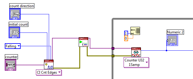
Hey mikeboxes,
Here is an example of the old-but-good of how do you want:
http://digital.NI.com/public.nsf/allkb/BA775B0E445BFA79482571FE0032CCEB
Tags: NI Software
Similar Questions
-
Stop the engine when detects digital impulses of the reflective light sensor
Hello
I am doing my school project and I managed to make the deepening of the engine via digital port of the USB-6008 by setting the Boolean value of output in a while loop with use cases, but now I faced a problem because I have to use it with a reflective sensor and stop the engine when he feels a digital pulse. The sensor is configured as a counter using PFI0 on the USB-6008 with a circuit that will send in a digital pulse for data acquisition.
How to stop the engine when the detector reflecting is blocked, and then start the deepening again when it is not blocked
Thank you
The top spot is always implemented as a counter. You must change the DAQmx create channel as a digital input and the DAQmx interpreted as a Boolean variable digital 1 channel 1 sample.
-
Hello
I finally found a way to do it. The analog sine wave is converted to digital and sampled. The consecutive values are compared and if the least significant bit (LSB) will change a pulse is sent to the stepper motor to activate a single step.
I've included the sub - VI who accomplish it for block engine and connector of particular Stairmaster I have. The front panel two sub - VI is quite messy, but the diagrams should be much clearer. The sub - VI get inputs from a third VI which I didn't understand. Then take a look at table VI of connector to understand. I hope this helps. A little messy but worked very well in the end of my application.
Thanks again for all the help. I appreciate that very much.
Kind regards
Sylvie abdo
Graduate student
Aerospace and mechanics Enggineering
University of Southern California
-
Hello!
My problem appeared when I tried to update my traditional NOR-DAQ legacy code to DAQmx.
I use 2 meter (meter 5 and 7 meter) on PCI-6602, to generate trains of pulses, as well as the lines of e/s digital port 0 (the form lines from 0 to 7). What I do in my request, it's that I'm starting to generate the pulse train on the output of 2 meters and after that I play with the State of digital lines.
Traditional, it was no problem to use the meters and digital lines at the same time, everything went perfectly, but in DAQmx, is not possible.
What's happening: I start generating train of pulses on the output of counters, no errors, but when I try to change the State of a line of digital port the generation of the pulse train is stopped. What happens when I start the task associated with the digital way.
My question is: is it possible to create a channel on digital lines without changing the channels created for meters?
Another thing that I managed to do with the panels 'Measurement and Automation Explorer' and Test for PCI-6602, is basically the same thing, I generate trains of pulses on the output of the 7 meter and try to start a job on the digital line, but I get an error:
"Error-200022 occurred in test Panel.
Possible reasons:
Measurements: Resource requested by this task has already been reserved by another task.
Device: Dev4
"Terminal: PFI8.On the contrary if I use the counter 0 or a counter 1 to generate trains of pulses I encounter the same problem.
What resources are used by 2 to 7 of the PCI-6602 card counters and the counters to 0 and 1 do not use?
Thanks in advance for any answer!
Ciprian
After doing some real tests on this device, I found that it is a normal behavior for the jury of 6602. This is because when you start a task digital all 32 lines are configured for digital i/o, so it replaces your meter operation. The article below the link explains a little more on this subject. You must start the digital task before the task of counter to use the features of both in your program.
2 meter and above will not work correctly when you perform digital i/o on NI 6601 or 6602
http://digital.NI.com/public.nsf/allkb/43F71527765EEC3886256E93006CD00C?OpenDocument
-
How to count the digital inputs of the sensor
IImsmd MicrosoftInternetExplorer4 normal 0
I use a PCI 6221 OR-DAQ device and I want to count the total number of times that a sensor is activated. The sensor is connected to a digital line.
Tadhg salvation,
If everything you want to count the number of times where the sensor is activate, the best way to ensure this is to use a line from the meter, in the case of the 6221 try pin 37, Cnt 0 Src/PFI8. And take a look at the example of counting code digital Events.vi that you can find from the Finder example under Hardware Input and Output > DAQmx > Counter measures > County Digital events.
Alternatively, if you use a digital line, just read the line, and if the sample is true variable increment held in one register at offset, similar to the Count.vi DI attached
I hope this helps.
-
How to set up digital channels to change values on the trigger and the counter in c#
Hello world!
I work with the driver NI - DAQmx 6025 and want to know, how do I configure the digital channels in c# for control lines different ports by trigger rising "PFI0" and the meter "ctr0.
digitalWriteTask = new Task();
digitalWriteTask.DOChannels.CreateChannel ("Dev1/Port3 / line0:7", "", ChannelLineGrouping.OneChannelForAllLines);
digitalWriteTask.Control (TaskAction.Verify);digitalWriteTask.Triggers / / how to configure to change Digital line on rising "PFI0"?
digitalWriteTask.Timing / / how to configure to change Digital line on County "ctr0?
-------------------------------------------------------------------------------------------------------------------------------------------------------------------------------------------------------------------------------------------------------------------
Hi an alle!
Am mit dem OR-DAQmx 6025 und möchte like wissen, die ich wie digital channels in c# konfigurieren muss um einzelne Ports der Leitungen auf dem Trigger "PFI0" und dem Zahler "ctr0' anzusteuern.
digitalWriteTask = new Task();
digitalWriteTask.DOChannels.CreateChannel ("Dev1/Port3 / line0:7", "", ChannelLineGrouping.OneChannelForAllLines);
digitalWriteTask.Control (TaskAction.Verify);digitalWriteTask.Triggers / / Wie konfigurieren, um den logical Pegel eines feature pine bei der der zu winds PFI0 goods?
digitalWriteTask.Timing / / Wie konfigurieren, um den logical Pegel eines pines beim ctr0 zu go digital?
NEITHER told me, with the NOR-DAQmx 6025 driver not supported!
ICH habe von NOR learn, dass dies mit der 6025 OR AQmx supported wird nicht!
-
count digital events on a counter with pci-6602 with reminder on the CVI
Hello
I use a card PCI-6602 with CVI 8.5 and I need trig on the event.
On each pulse, I received, I need to do some actions like increasing a counter, send a message to Rs232 etc... I want to do no loop by checking that the value of the counter has changed. I would use a reminder to run this code only on the value of edge or a counter event.
My problem is that I don't know what function for this. Is it possible to get an event on a pci-6602?
Thank you
James
It's true. If a earlier without change detection and it works.
Thanks for your help.
-
Function DAQmxRegisterEveryNSamplesEvent can be used for the counter input channels
Hi all
I have a request to count the number of digital pulses. I want to know the time of impulses coming which start from 1 and an increase in later, 4 as 1, 5, 9, 13... The time interval between each pulse is not a fixed value. So I tried to use DAQmxRegisterEveryNSamplesEvent and DAQmxCreateCICountEdgesChan functions. But afterI calls the DAQmxStartTask function, it has always failed. The advice that I used is the NOR-PCIe-6320. Here's the part of my code.
DAQmxErrChk (DAQmxCreateTask("",&m_taskhandle));
DAQmxErrChk (DAQmxCreateCICountEdgesChan (m_taskhandle, "Dev1/ctr0", "", DAQmx_Val_Rising, 0, DAQmx_Val_CountUp "));
DAQmxErrChk (DAQmxRegisterEveryNSamplesEvent (m_taskhandle, DAQmx_Val_Acquired_Into_Buffer, 4, 0, EveryNSamplesCallback, this));
DAQmxErrChk (DAQmxStartTask (m_taskhandle));I don't know the reason. Can someone give me help. Thank you.
Yang
DAQmxRegisterEveryNSamplesEvent only works with the buffered in memory tasks. That's what you should do anyway (if you want to use the callback or not):
1. make your external signal the sample clock (DAQmxCfgSampClkTiming).
2. use one of the basics of internal time as the source (DAQmxSetCICountEdgesTerm).
Each sample you read will give the count in ticks of the time base. Multiply the number by the base of your time period and you now have a timestamp. Keep in mind the counter roll to 2 ^ 32 therefore account for this in your program.
The recall is not necessary, but it is useful that you can make sure that you block your main thread until the samples are available.
Best regards
-
When the output of the counter, which means "implicit synchronization"?
Hello
I'm trying to generate a simple pulse train (as in This example). But I want the EXTREMELY precise timing. As accurate as possible given my device series X DAQmx.
So I was wondering if someone could explain to me what means "implicit synchronization." Is that mean that the counter will choose the 'best' timebase accordingly?
Can I just force the counter to use the time base of 100 MHz reference to ensure that the time is as accurate as possible?
When you specify the implicit synchronization, you say DAQmx to generate pulse train dictates when the meter should update its output rather than other mechanisms (such as the sample clock). It is not related to specify what timebase counter must use as its source when generating. DAQmx should choose a base of default time suitable for you, but you can explicitly set this via the property node of DAQmx channel-> counter output-> General Properties-> Timebase counter-> Source property.
Hope that helps,
Dan
-
I read an encoder signals of pulse with the CAI (meter high speed) of labview and NI USB Daq 6009. So I tried to do it the easiest way, I found, by using the labview "component" (I don't know the exact name) of the attached photo. I account the impulses of wiring just a digital indicator on the port of outuput of 'data' of this 'element', and it seems to work perfectly. But my problem is when I try to reset this counter. I tried to connect a Boolean control at the port of entry 'stop' of this component and it worked when I click control Boolean true, but when I turn to false, it does not count the pulse more. It counts only the pulses again when I press the buttom game and press stop to run the VI again.
The block that you use is an express vi, it will not certainly what you want, use discrete vi.
You must initialize the acquisition of data outside of a while loop and then inside the loop States (Please search for state machine architecture) as count, pause, reset, stop, etc.
You can modify this example and add States in for the while loop as a result. Also try the example finder, labview comes with plenty of examples for the daq hardware.
I hope this helps.
-
I have a question about the order of execution. In the WHILE loop, I have two things to measure, period and tension using the DAQmx READ functions for voltage and the meter. In the end, I want to collect these data as points almost simultaneously as possible, as a pair and then send them together to another piece of code (not shown here) which them will result in some sort of command for an engine. It would be run, and then I want to perceive the tension and the period at a time later and do the same thing.
(1.) I'm a little confused on what the meter of the READ function is back because it's a table. What is a picture of? I thought that it was up to the value of the individual periods between rising edges. The output of the counter 1 DBL d's a table. How many elements in this table, and what determines the size of this table? Are the elements of the array the individual delays between the edges? How many values are stored in the array by executing? We take the AVERAGE of the last 15 items, but do not know if we are throwing some of the data or what. How to understand the composition of this painting? How can I change the composition of this painting? Is it possible to measure only one period at a time, for example the time between TWO edges?
2.) Will this WHILE loop execute as it gathers tension and a "period table ' (remains to be understood by me) by TIME running in a loop? In particular, we want that the value of the tension associated with the value of the AVERAGE of the period "array", so we can use two data items to create orders of next control every time that the two values are reported. The structure for the delivery of vi will be attached data in pairs like this? I understand that one of the READING functions run not before the other function of READING in the WHILE loop. I want that the period "means" and "strain (Volt) collected at the same pace. This vi will he?
Thank you
Dave
Hi David,
I suggest including the DAQmx Start Task function. If it does not start before the loop, it starts the loop and work very well, but it is not as fast and efficient. In the model of task status, task wiill go to run the checked each iteration of the loop and then back the time checked running when it restarts.
The status of the task model: http://zone.ni.com/reference/en-XX/help/370466V-01/mxcncpts/taskstatemodel/
Kind regards
Jason D
Technical sales engineer
National Instruments
-
How to generate a trigger when the arbitrary
Hi all
I have a digital output pci card 6534 and an analog output pci card 6723.
I would like to generate a material long pulse sequence timed. The 6534 has 32 MB memory on board, so it is good to do a long sequence. The 6723 will run out of memory if started at the same time. I would therefore trigger the 6723 at a later date. The boards are connected with rtsi.
I see 3 ways to do (well that I know how to do, but the first two would be more elegant):
(1) generate a sequence of digital pulses on ports (i.e. how that), then convert a line of port online rtsi (don't know how to)?
(2) generate a trigger to the arbitrary point on the rtsi lines (don't know how to)?
Go 3) with 1) physically connecting a port to a line PFI on the analog card.
I have not found a way to send a trigger at some arbitrary point with the RTSI. Instead of this I went with solution 3) and related digital outputs analog card PFI channels.
-
How can I change the data format of the digital display of the digital meter?
I created a screen that uses digital counters to display data. Each meter has its visible digital display so that the user can see the level accurately. I have changed the format of the data from the meter to 2 digits of precision and want to display to have the same format, but there seems to be no way to do it. The digital display is locked to 6 significant figures, which will be confusing for my users. I know that this was possible in previous versions of LabVIEW, but was somehow lost to 8.6.1 and 2009.
I am aware that I could do some "work-arounds" with channels or replacing the digital screens with digital indicators, but it is not acceptable. How can I change the properties of digital signage?
Hi AEI_JR,
on the Properties dialog box, when you set the display format of the counter, you will find a switch to choose between 'Digital' (the default) and "digital display"...
-
create 4 pulse digital output at the base of the ttl input signal
Hello
I am a beginner in Labview and would welcome advice on how to solve the following problem.
I'm setting up a train of pulses TTL and would like to send in Labview as input. Each falling edge detected on the input signal, I would like to as Labview to generate 4 pulse digital output. For each output pulse, I would like to be able to specify the period and duration. The image should illustrate more clearly, with the figures showing the expected scale.

System: NI PCI-6733 data acquisition card, Labview 8.5
My daq card has 2 timers 24-bit and 8 e / s digital, but I don't know what the best approach is to create between the pulse output of 4 to 8 of this precision... should it be handled at the hardware or software level? And how would I go about it
Thank you
-Sidney
Hi noli.
I found the problem, in fact PCI-6733 support only avoiding the digital output. The timing of software is limited to 1 kHz in case better.
I'm sorry, but this function is not possible with a PCI-6733.
Concerning
-
Y at - it a messaging of iOS application that updates the counts unread for all folders?
I went through a considerable amount of effort to organize my e-mail on iCloud in several folders, some nested, including using filters to Apple to sort my emails in these folders. I was really surprised to see that the mail iOS app is not able to maintain unread accounts next to these folders. I think that it is possible to declare as "Inbox", but in addition to the clutter of dozens of them, he "flattens" and resumes the structure unnecessarily. What I want is the the folder tree is as with the counts read next to them. Parent folders contains the sum of the counts unread subfolders. If any of you have used 'Claws Mail', you'll know exactly what I mean.
What is happening is that the unread number is updated only when I visit the folder. Visit dozens of folders at the same time, it is tedious and unacceptable. I'm really curious to know what Apple had in mind when creating this filter mechanism without providing the counts unread next to the folders. It really beats the screening point, and I get bored to see mail in due course. I tried every setting I could find to the counties to operate without success.
Is there any application to mail out there that can do this?
A second problem with the filters of Apple on the iCloud is that iOS doesn't let you get to iCloud.com via Safari to manage your filters. You use Chrome or non - iOS to connect to iCloud.com system. I don't see why this is so.
You can press and hold the icon Refresh (semicircular arrow) into the URL bar "Ask Site Desktop" will appear and then press that.
Maybe you are looking for
-
Updates installed, keep repeating to be updated again, count locks when idle.
HelloI recently changed my antivirus software.Now I find that 2 m/soft updates keep repeat to be installed, I went to installed updates, they were loaded on two occasions, I've hidden updates. How can I correctly solve the problem? Also when the pc i
-
After I succesufully download service pack 3 and restart the computer, need me a black screen where I have the options of safe mode, safe mode with network, last known working configuration and start windows normally. Whenever I have select start nor
-
Smartphones blackBerry address book format
I had a Moto Q phone and was able to make my list of with the name of the company address book (Outlook) then the name of clients is possible on the backberry? Robbie
-
the orientation desktop icon - is there a way to keep my icons in a vertical rather than horizontal?
I want to keep the icons just above the taskbar in an upright position without them returning to the horizontal position, they are when I first start my laptop. Is there a way to keep my icons in a vertical rather than horizontal?
-
How to find and install the audio driver for HP A5HOOEA
Hi all, have a HP Pavilion g6-1210ea 15.6 "laptop. Can't find an audio driver to install Operating system Windows7, error message keeps coming up no audio device installed Thank you, Sue