Graph XY containing 5 parcels
You want to have a XY Chart with 5 locations. Volt1-5 volt based on the pressure.
Tried, but it did not work. Why?


Hi Michael
You have connected the terminal count to the index of the table, instead of connected terminal iteration.
Try the following code.

Thank you
AREV
CTO | RAFA solutions


Tags: NI Software
Similar Questions
-
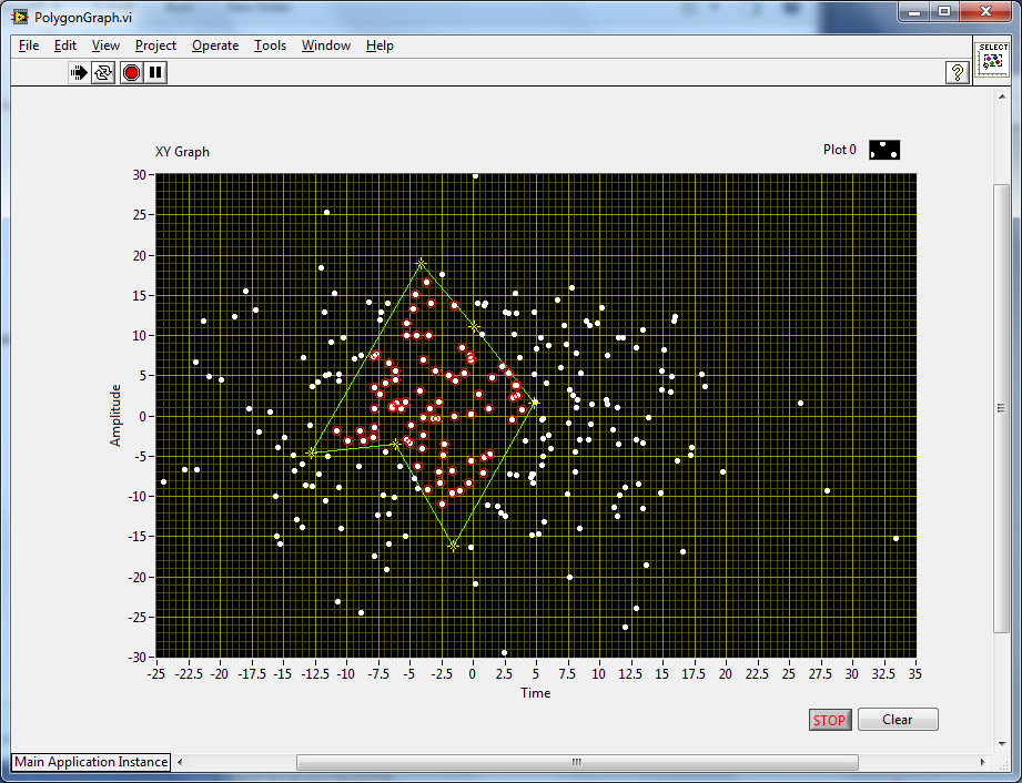
How to choose a set of points in a graph xy contained in a draw of the area with the cursor?
I use the tIhe XY graph to draw a Pointcare intervals RR (heartbeat) representation. I would like to use the mouse to draw a polygon around the points of interest and get their index in the original array. Thank you to me a strategy-oriented!
Olivier
It seems more difficult to describe in words than just after a simple example. Simply click on the graphic to add sliders, drag them around as you wish and see the included points. I used a 1-bit bitmap to detect the inner points and the draw several VI points for the polygon image.
I sort the points so that the polygon is filled completely, form then, sometimes you see pass all of a sudden. Not a complete solution, but a good start.
-
Newbie - waveform graph axis graduation issue
Hi all
I'm new to studio of measure (v8.0 with .net c# 2005) sorry if this question has been answered 10 times more, please feel free to point me to a previous thread.
I have a request to:
drive voltage analog sampling at 10 Hz reading 1 sample per tick.
standard waveform graph axis X and Y and a plot as a collection of doubles.
So far, it's something pretty simple and I can get all this work in the code example.
My problem is that I want for my X axis to read between 0 and 1800 with the major divisions of 100 and minor divisions = 50. I would like for my actual graph however contain 10-point increments, so that would mean that there will be 500 points between each minor division.
I looked down through the properties of the axis and I can't enough find the properties that I need to set.
Can someone help me please.
Thanks in advance.
Steve
Hi Jamie.
Thanks for the reply. I spent all the update yesterday my system of measurement studio 2012 + Dev Studio 2010.
I put these settings, looking more closely at my data, I have a problem with my data acquisition analog voltage so I'll search through my solution and start a new thread, as I'm getting 3 times more data that I need, so it is causing my chart to be wrong.
Thanks again.
Steve
-
Hello
I dynamically change the speed of a motor in a pre-defined curve. The engine follows this curve by adjusting its speed constantly.
Now I want a graph showing the two parcels:
1. predefined curve (table 1 d)
2. actual engine speed (stream)
This would allow me to determine visionally how the engine follows the predefined curve.Initialize a 2D array, a line containing the expected curve and the other containing all NaN.
For each iteration of the loop, replace a NaN in column [i] with data. Here's a quick example (LabVIEW 8.0).

-
How to set the vertical position of the oscilloscope (Simulation)
Hey guys...
I think do a very basic oscilloscope in labview (simulation only).
So I'll show 2-4 channels to the oscilloscope. For this I will use a waveform graph and show the parcels of 2-4 in the same graph.
But how to define the vertical position of the individual parcels (channels) for comparison?
Suggest an idea please...
Make additional changes the values in your table do you do whatever will be will be incorrect. For the offset adjustment, assign each parcel at a different scale y and set the minimum and maximum of the scale up and down the waveform.
-
Hi, I have two decimal strings, each of them contains the numbers change over time. I want to plot them on the graph XY, a string for each axis. Can you show me how do?
This is not a formula, but a constant simple schema of a table complex. Wire remains, then do a right click of the terminal of the initializer of the feedback node and select "create constant. That should do it.

-
I need autoscaling on a graph XY to ignore a parcel
I'm doing the autoscaling to ignore one of the three locations on a XY Chart. My program trace a set of data points, that approach and exceed a critical level. My chart has three parcels: under the limit points are green points, points above the limit are red dots, and the limit is a horizontal dotted line extending between two points. Initially, endpoints of the line have been established in the vicinity of the x-values of data. Autoscaling worked very well, of course, but the line analyses as well as the data they are traced. This limit is a fixed value, I like the line to stretch completely on the screen and stand still.
To this end, I put endpoints beyond the limits of the x values. Now, auto-scaling of the tracks with the endpoints of the line and the actual data are compacted in the middle of the graph. Is it possible I can forward the autoscaling only with data points and ignore the line, or is the best option, just write my own code, autoscaling?
Thank you!
You could wirte your own automatic scale, but I think is easier to do something to change your horizontal line of a parcel of a cursor. You can use the list property of cursor or active (the control graph) the cursor property to control positioning and the color of the cursor, and you have not to worry ever its end points (there no).
Chris
-
Trace graph XY forever hiding other parcels
Hello
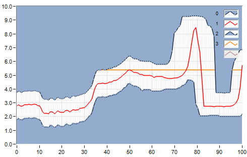
I use a graph XY draw certain limits. These limits are indicated by the plot 0 and parcel 2 , that's why I put them to "Fill in positive and negative infinity" respectively.
It is, I now have another plot (trace 3) to display that fall into the 'limits' designed by plot 0 and 2. The result? Parcel 3 is covered almost entirely by the other plots with the "fill up to.." option.
TL; DR: is there a way to make the plot 3 display along its length without being under the filling for x infinite plots?
Current result:
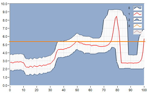
Expected result:
Changing the order of the plots and setting limits to the end.
-
Graph DVT does not meet width of full container
Experts,
I have a chart bar DVT in my Panel tabs with 'AFStretchWidth' located inside a panelHeader. But my graphic is not stretching to fit the entire screen. I also tried to set the 'AFStretchWidth' in the graph, but unproductive.
for example: panelheader having
-panelTabbed styleclass set 'AFStretchWidth' containing
-dvt styleclass value "AFStretchWidth".
Any ideas how to make the chart fill the width of the full container?
thnksMake sure that the tab of the Panel (or parent of the DCT component) is tense.
DYNAMIC_SIZE value dynamicResize value of the property of DVT. -
Jena adaptor: possible bug in Graph.contains)
I get some weird failures in some test case after porting some existing Jena client code to use the Oracle back-end, and I think I've isolated to an apparent bug in the method GraphOracleSem.contains (node, node, node). The method does not appear to be triple existing, when one of the nodes is a URI that ends with a slash (' / '). I have the following test code:
+= == Java code trace start = +.
FileInputStream fis = new FileInputStream("C:/test.owl");
Chart GraphOracleSem = new GraphOracleSem (oracle, "TEST_MODEL");
Model ModelOracleSem = new ModelOracleSem (graph);
try {}
model.enterCriticalSection (Lock.WRITE);
Model.Read (fis, baseUri, "RDF/XML-ABBREV");
Model.Commit ();
} catch (Exception e) {}
Model.Abort ();
} {Finally
model.leaveCriticalSection ();
}
Node n = Node.createURI ("http://www.example.com/test1/");
If (graph.contains (n, Node.ANY, Node.ANY)) {}
System.out.println ("found node:" + n);
} else {}
System.out.println ("did NOT find node:" + n);
}
n = Node.createURI ("http://www.example.com/test2");
If (graph.contains (n, Node.ANY, Node.ANY)) {}
System.out.println ("found node:" + n);
} else {}
System.out.println ("did NOT find node:" + n);
}
+= == End Java code trace = +.
And the following content to test.owl:
+= == File start OWL = +.
<? XML version = "1.0" encoding = "UTF-8"? >
< RDF: RDF
xmlns:RDF = "http://www.w3.org/1999/02/22-rdf-syntax-ns#".
xmlns:rdfs = 'http://www.w3.org/2000/01/rdf-schema# '.
xmlns:OWL = 'http://www.w3.org/2002/07/owl#' >
< owl: Ontology rdf: about = "http://www.example.com/test1/" >
Test ontology < rdfs:label > < / rdfs:label >
< rdfs:comment > an example of an OWL ontology. < / rdfs:comment >
< / owl: Ontology >
< owl: Ontology rdf: about = "http://www.example.com/test2" >
Test ontology 2 < rdfs:label > < / rdfs:label >
< rdfs:comment > another example of an OWL ontology. < / rdfs:comment >
< / owl: Ontology >
< / RDF: RDF >
+= == OWL file end = +.
Execution of test code produces the following output:
Did NOT find the node: http://www.example.com/test1/
Found the node: http://www.example.com/test2
As you can see, the only difference between the way the two resources are defined is that of one URI ends with a slash and the other not. It is indeed a bug in the Oracle Jena adaptor? Is there no workaround solution to get this to work with my existing data? Thank you.Thanks for your test case. I reproduced it myself. This is a corner-case bug in 2.0 adapter Jena. I already put in a small fix. Please email alan wu at oracle dot com dot so that you can check the fix yourself.
See you soon,.
Zhe Wu
-
I need help with graph XY (about the colors of the parcels)
Hi have a XY Chart on which I draw many plots. The number of these plots is VARIABLE, and I can't keep it fixed. The problem is that default Labview gives these parcels of DIFFERENT colors.
My request is this: is it possible to force Labview to give me the SAME color for ALL plots without going to change them by hand from the Panel?
And how? I spent a lot of time to understand for a long time, but I never able to do.
Thanks in advance
You must use property nodes. See here.
-
graph XY on the TAB container does not update
Hello
I have attached a simple VI, and I understand why I see this behavior:
When I run the VI then the first tab is visible (where the xygraph is located), I get what I expect: I calculate the offsets, and I redraw the graph with the property node.
But if I run the VI during the second page of the TAB is visible, I get a wrong result, the graph does not the calculation of the compensation and modification on the chart. (Table gives zero element)
This means that, if my graphic is in a TAB page which is not displayed, I can't use its property nodes?
Thanks for the help!
Are yous because this for any node property or specifically the sliders? You see the same behavior if you do the invisible Grpah XY but leave on tab 1. It seems that the properties of cursors do not work correctly if the XY graph is not visible. I consider cela a bug.
How do you determine the values of the cursor? A user highlights them, or their calculation and setting in? If hardset or calculated at a given time, store the values of cursor and use them instead of watching the cursor property.
If the user selects the, use the structure of the event to trigger an event when the user releases the cursor. Get slider right there, store them and use these values.
-
I'm new to LabVIEW. IAM trying to display two plots on a graph using the node property value charts. I tried to feed the two signals into a signal of fusion and then in the value property node, but it did not work. Then I tried to build a table of two signals and it powers the value of hardware node. It did not work. What escapes me, should I use the node property value this way?
-
Graph.DefaultPlotRenderers.ReplaceAll () does not change to GUI
WPF C#
Hello
I don't know what I'm doing DefaultPlotRenderers example provided with NEITHER Studio differenly. I see in the debugger that DefaultPlotRenderers object contains nothing or my custom settings (based on the option that select). This is what it looks like the debugger in the example of OR.
Here is my code and any help would be appreciated to greately.
using System;
using System.Collections.Generic;
using System.ComponentModel;
using System.Linq;
using System.Text;
using System.Threading.Tasks;
using System.Windows;
using System.Windows.Controls;
using System.Windows.Data;
using System.Windows.Documents;
using System.Windows.Input;
using System.Windows.Media;
using System.Windows.Media.Imaging;
using System.Windows.Shapes;using NationalInstruments.Controls;
using NationalInstruments.Controls.Primitives;
using NationalInstruments.Controls.Rendering;namespace FireflyMmwDiagnostics
{
partial class GraphLinear: window, INotifyPropertyChanged
{
Private bool m_includeMarkers = true;
public boolean IncludeMarkers
{
get {return m_includeMarkers ;}
Set {m_includeMarkers = value; OnPropertyChanged ("IncludeMarkers"); }
}Public Overridable event PropertyChangedEventHandler PropertyChanged;
public virtual void OnPropertyChanged (string name)
{
Manager PropertyChangedEventHandler = PropertyChanged;
If (Manager! = null)
{
Manager new (EC, PropertyChangedEventArgs (name));
}
}
Private readonly PlotRendererCollection PlotRendererCollectionWithMarkers = new PlotRendererCollection();public GraphLinear()
{
InitializeComponent();DataContext = this;
}public void AddData (list of data
{
T [---] arrayData = new T [data. County, data [0]. Length];< data.count;="">
{
Create the plot object
AddPlotToGraph (data [conspiracy]. Length, "");Convert the list to a table
< data[plot].length;="">
arrayData [field, point] = data [conspiracy] [point];
}Assign data
Graph.DataSource = arrayData;
}' Private Sub AddPlotToGraph (dataSize int, string label)
{
Brush brush = Utility.RandomBrush ();
ChartCollection
Plot = new Plot (label);
LinePlotRenderer linePlotRenderer = new LinePlotRenderer() {Stroke = brush, StrokeThickness = 2};
LinePlotRenderer linePlotRenderer2 = new LinePlotRenderer() {Stroke = brush, StrokeThickness = 8};PlotRendererCollectionWithMarkers.Add (linePlotRenderer2); Store away alternating plot setting
parcel of land. Renderer = linePlotRenderer;
Graph.Plots.Add (plot);
}' private void CheckBoxIncludeMarkers_Click (object sender, RoutedEventArgs e)
{
If (IncludeMarkers)
Graph.DefaultPlotRenderers.ReplaceAll (PlotRendererCollectionWithMarkers);
on the other
Graph.DefaultPlotRenderers.Clear ();
}This is an excerpt from another class where I make a call to show this graph...
GraphLinear graphLinear = new GraphLinear();
graphLinear.AddData (listOfSmaData);
graphLinear.Show ();If you need the motor field set, and then manually update render rendering on all parcels engines would be the way to go.
If you leave the field undefined rendering engine, you could switch between two groups of default field rendering (i.e. to save both
linePlotRendererandlinePlotRenderer2in the collections and the Manager of the box update with a collection or another). -
Read from worksheet and chart several XY graph
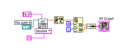
I'm reading a text file by using the function "reading worksheet. Then, I want to plot the data on a single graph XY.
The text file contains 4 coloums and the first coloumn is X axis and the rest are for Y axis. I'm not able to get the multiple locations.
However, I could get it to draw when only one chart must be drawn (only 2 coloumn in the file). I have attached my VI and a photo here.
I need help to draw several graph XY of the text file with 4 columns.
Hi Bachna,
You need to build an array of clusters in several locations on a xy chart. You have created a cluster for a parcel. Again, you try to build a similar clusters for several plots.
Kind regards
SrikrishnaNF
Maybe you are looking for
-
Overheating problem on my Equium A60
Hi all I've posted a few more heating problems, a few months ago I've followed the instructions and cleaned the areas necessary, but the problem persistsI ve downloaded a program that monitors the temperature of the different aspects of your machine,
-
Tecra M5 does not record the date and time - battery RTC or CMOS checksum is inconsistent
My Tecra M5 PTM50E reverend new does not record the date and time. I loaded RTC battery for 8 hours when electricity is on in the said user's manual. I don't know where is the problem. The BIOS settings are respect after power is on. When I change an
-
where to get older versions of bios
Hi, I wonder where I can get the old versions of the bios for the motherboard of an h8 formosa 1409. now its got 8.14 friend. Thanks in advance.
-
using a line of meter / digital as a trigger to reset another line of meter
I am using an SMU-6366 device, and I use an encoder that has 3 exits; 2 outputs, A and B, which produce 720 pulses per revolution (both 90 degrees out of phase) and the third release, Z, is a marker that once each complete turn of the pulses. I use '
-
Example: elitebook 2570p: ELITEBOOK 2570p MSATA
Hi I install a disc hard msata in my hp elitebook 2570p.