graphic square axes WPF
I need to do ScatterGraph with axes perfectly square, which also should fill his tank. It displays the circle unit (RADIUS 1, positioned to 0), then no square axes are very annoying.
What I do now, something is li, but he is not perfectly square axes.
' Private Sub graphWrapper_SizeChanged (ByVal sender As Object, e SizeChangedEventArgs)
{
If (squareArea)
{
int size = (int) Math.Max (0, Math.Min (graphWrapper.ActualWidth, graphWrapper.ActualHeight) - 10);
Graph width = size + 35;
Graph height = size;
Graph HorizontalAlignment in the Group System.Windows.HorizontalAlignment.Left;
}
}
You can use the text following SizeChanged Manager of events on a graph to maintain a square plot area:
private void OnGraphSizeChanged( object sender, SizeChangedEventArgs e ) {
Thickness margin = graph.Margin;
Size plotAreaSize = graph.GetPlotAreaSize( );
Size current = new Size(
plotAreaSize.Width + margin.Left + margin.Right,
plotAreaSize.Height + margin.Top + margin.Bottom );
double ideal = Math.Floor( Math.Min( current.Width, current.Height ) );
graph.Margin = new Thickness {
Right = Math.Floor( current.Width - ideal ),
Bottom = Math.Floor( current.Height - ideal )
};
Tags: NI Software
Similar Questions
-
Graphic selection of WPF controls
Is it possible now to know when the user clicks on the marker or annotation? It did not work in v.2012.
As mentioned in the question of How to get click on the slider or the annotation , only the
GetChildrenAtPointproblem has been solved in 2013 Measurement Studio, which is the latest version available at this time. You can now hit test against the target, line and parts in the form of graphical sliders Cross and annotations when mouse events overview in the graph, but as labels parts management will not return a hit test result. -
graphical annotation target WPF is hidden under the plot
Target of annotation is hidden under the ground and cannot interact with. Annotation label is positioned on the same parcel and is draggable. No plot, everything works fine. When I zoom sufficient for this plot is not too thick, it also works very well. See the attachment, it a circle of barely visible annotation under the plot, and it cannot be moved. If I click on the part of the circle that is not covered by the plot, it can be moved.
Measurement Studio 2013, VS 2010, 64-bit Windows 8
It is an attached property that is defined by the base class
LayeredGraph. In code, you would useGraph.SetPosition( annotation, GraphLayerPosition.AbovePlots ); in XAML,ni:Graph.Position="AbovePlots". -
Can build, but can not run a simple WPF chart
Hello
I just got my NI Measurnments Studio package and I try to add a graphic to my WPF c# application but I have questions that I have not seen in the examples of the trial. Before you buy this package, I changed one of the examples of the trial to draw my own data and it worked beautifuly. Now I tried to do the same thing in my own project and it builds without error but I get InitializeComponent() exception when I try to run it:
"The call of the constructor on type"NationalInstruments.Controls.Graph"that matches the constraints of binding specified threw an exception."
That's what I have:
- Added to my project references (VS 2013)
C:\Program Files (x 86) \National Instruments\MeasurementStudioVS2012\DotNET\Assemblies\Current\NationalInstruments.Common.dll
C:\Program Files (x 86) \National Instruments\MeasurementStudioVS2012\DotNET\Assemblies\Current\NationalInstruments.Controls.dll
C:\Program Files (x 86) \National Instruments\MeasurementStudioVS2012\DotNET\Assemblies\Current\NationalInstruments.Controls.Graphs.dll
- Added to this, notably in XAML
"" xmlns: or = 'http://schemas.ni.com/controls/2009/xaml/presentation '
- And added this chart control to XAML
<> area of Label = "Channel 1" x: Name = "Plot1" / >
<>area of Label = "Channel 2" x: Name = "Plot2" / >
Nothing else behind it, so I should at least power run and see a graph empty, right?
Please advice.
Thank you!
I got it work. Basically, it was licening known issue in 2013 VS. I had the .licx added manually in my project file. Here is the email that I received or who has been very useful:
"I noticed that you use Visual Studio with Measurement Studio 2013 2013. Currently measure Studio 2013 is only officially supported by Visual Studio 2012, however, many of our clients were able to make it work with Visual Studio 2013 Measurement Studio 2013. We have an article for the knowledge base that walks by working with Measurement Studio 2013 in Visual Studio 2013. It might be good to make sure you followed every step through this article: http://digital.ni.com/public.nsf/allkb/C51E3B38578FAD2786257C070069F386
It looks like you are using the correct assemblies, and we were able to test the XAML for our side. It works beautifully, so it doesn't seem like there's something is happening with the code. Another thing, we can try is to clean the Solution and regenerate the Solution in Measurement Studio. It will be a good step to make sure that no old persistent files. »
Thank you
-
set chart properties in code-behind
I am trying to add graphics dynamically in WPF code behind. It works fine, but I can't find a way to set the default interaction for zoom and pan interaction - is it possible to do in code-behind?
Yes, you can affect both the column admitted
InteractionsandDefaultInteractionon a chart for all validGraphInteractioninstance. For example:graph.DefaultInteraction = GraphInteraction.Zoom;
graph.Interactions = new GraphInteractionCollection { GraphInteraction.Pan }; -
I installed the toolbar of Babylon and babylon pro. I worked with her. But I can't found the average words in the graphic square. I connect to the internet now.
Hello
1. what version of Windows operating system work?
2. do you get this error message on a particular Web site?
3. What is the full error message that you receive?
4 are you not able to use the toolbar to search for Babylon or you are having a problem connecting to Internet Explorer?
5 have had any changes made on the computer before the show?
Kindly get back to us with information, so that we can help you better.
-
That's what I'm trying to do. I have a file periodic_chan3.bin which is sampled values of three channels of periodic signals in interlaced format. The data is stored in binary format (long of floating point of the double procession) DBL and big-endian representation. I am reading the file and draw all the three waveforms on the graph of a waveform. The data has been saved from time zero, with a sampling frequency of 100 samples per second. Then I scale the x-axis of your waveform graph so it displays the time in seconds.
So I try, on the wave of the chart to create three sets of cursors and cursors to display the average value of each of the three waveforms. The color of the cursor Y for a given signal average must match the color of the display of the waveform on the chart. For example if the graph of the signal is displayed in red the cursor there shows the average of this signal must be red.
What happens when I do not open the file I see a white contour mesh a sine graph, a graphical square and sawtooth chart. I can't seem to trace the three waveforms seen clearly with the three above-mentioned distinct colors. I can't seem to sort correctly and represented as mentioned above.
I would also help with the calculation of the average or expected from each of the three periodic waveforms.
Attached are the files please help. Pgm4 is the VI, and periodic_chan3 contains the data that needs to be sorted. I'd be very happy if somene were able to fix the and submit the changes so I can see how it works. Thank you.
Edit: I get an error that says periodic_chan4.bin "is not a valid extension of an attachment" so I'm not able to uplad it. Is there a way to othe I could download it?
Xtasy26,
In your post you mention that you try to view 3 averages of waveform, however your code is showing that you are broadcast 4 values. This might be the reason why your getting the different forms of data. Instead of an array of all the waveforms 1, then a table of all 2 waveforms and a waveform table 3, you get a mix of all three in each of your waveforms.
To calculate a moving average or mean that it is actually an integrated in the example in BT sound finder called "running Avereage.vi calculation"
You can also view the attachment to see Multiple waveforms channel displayed on a single chart.
-
When I publish files in files oam edge out huge...
When I publish dashboard to oam animated files there is no correlation between the size of the final file and content. resulting in large files. How can I fix it?
size of the model is 960 x 350 publish on oam for download following edge...
Essentially, I have a project in which I inserted a sequence of JPGs, and some layers of text from there I have to publish a 54 mb file! THEN I deleted the jpg sequence and republish 54 mb, then I deleted the text layers and insert a graphic square as a placeholder for allowing me to publish another wise man empty comp...
The seq jpg is not exceed 2 MB that text layers may be using webfonts happens something here... In any case I do not understand why Im getting massive files... The ideas people?
Hey Chris - MCO is nothing more than a copy of the original files + a few extra configuration files.
I check the pictures folder and see how big the combined assets total.
Darrell
-
Roots/path & this.parent - asking for simple clarification
Step - the sandbox is where all things happen.
MovieClip - an object that can be placed on the stage or in layers or attached to other clips.Layers of MovieClips on stage
Example:
Stage > MC1 > MC2 > MC3
Family analogy to the hierarchy:
Environment > Grand Parent > Parent > child(1) for access to the control of the MCs of the Document (stage) class
-If the STM is brought on stage and given names use you that name to control them. (Logic)
-If an object is dynamically added to the step how is it accessible? (Confused)2) access control of MCs of MCs on the stage who '.as' file by running.
-Can change the properties of other MCs MCs? As scaleX, scaleY properties view? (Unknown/confused)'This' and 'Parent '.
-this.parent.mc - when it does exactly?
-parent.mc - where it is exactly?
-mc - when it does exactly?Usage example: Stadium > MC1 > MC2 > MC3
In step (Document class) is access MC3 then use: "mc3".
When MC3 accesses MC1 use: "this.parent.mc1".
When MC2 accesses to use on stage: 'scene' example 'stage.width.
Vaguely is that kind of how it works?
QUESTION--= =-If someone is willing to clarify all the pieces of this or has a fan friendly use of 'This', 'Parent' and appropriate use of the roots depending on where you are on the stage or in a MovieClip and how to properly refer to an another MovieClip or the scene would be useful. Forgive me if I have an abuse of words, terms. I use Adobe Flash Professional CS5 and AS3.0
In AS3 you can reference objects by name or by reference. In AS2 you mainly referred to objects by name, so this may be confusing for some newcomers to AS3. A name he set, for example, when you drag a clip to the stage and type an instance name. A reference, on the other hand, is just an object that points to another object. You must create a reference when you dynamically create some MovieClips, for example:
var mcRef:MovieClip = new MovieClip();
The variable "mcRef" is a reference to this new MovieClip, however it didn't name. You can use "mcRef" as you would a named instance, the definition of the properties as "mcRef.x = 100", etc.. A reference is much more useful than a name, because it can be spent in the different application fields for you to access objects that would otherwise be difficult. For example, you can use a reference to refer to a deeply nested MovieClip without having to type it every time:
var mcRef:MovieClip = myMovie1.nestedMovie1.nestedMovie2.nestedMovie3;
mcRef.alpha = 0.5;
The "parent" means the container that particulat object resides in. So take the example of "mcRef" above, the "mcRef.parent" would be "nestedMovie2". "mcRef.parent.parent" would be "nestedMovie1" and "mcRef.parent.parent.parent" would be "myMovie1". For dynamically generated clips, the parent will be the subject of container you called "addChild()" add this child element to the display list. For example:
myParent.addChild (myChild);
The property "this" refers to the scope at which you call it. So, if you are in the document class, you call 'this', he referred to the scene. If you are in an external class, then it refers to the instance of the object of this class. This will allow you to access all of the properties in this scope, such as "this.x = 0", "this.alpha = 0.5", etc.. ". It will also allow you to cross to the top of the display list as in the use of «this.parent» Keep in mind that you do not explicitly refer to 'it', it is assumed. So you can easily just say 'x = 50' and it's the same as "this.x = 50".
Virtually all of the common properties are public (like x, y, scaleX, alpha, etc.) so as long as you have a reference to an object, you can change its properties from anywhere.
In general, you want to give their own class objects (of right in the library and go to the linking options). So lets say you have a graphic square, you can give it a class of "Square". If it's just a chart, with no particular feature, so he can't give it an external class file (IE Square.as). If you want it to have some custom methods and properties you need this external class. However, if you just want to add a static image on stage, then you can just use the auto-generated class. Anyway you if instantiating the object as follows:
var mySquare:Square = new Square();
addChild (mySquare);
If you want to add another square that you could do this instead:
var mySquare2:Sqaure = new Square();
mySquare.addChild (mySquare2);
Now, if you want to access mySquare2, you always use the reference "mySquare2.x = 100" for example. Stays of reference within the scope you created. Thus, for example, the following would NOT work: "mySqaure.mySquare2.x = 0". That works only with a named instance, not with references. You can, however, still use "mySquare2.parent" and which refers to "mySquare.
I hope this helps.
-
Graphical WPF reset the Axes of origin
Hello
Is there a way to reset a horizontal axis (0) originally?
I already used ResetZoomPan(), but this only the definition panoramic and zoom to its original state.
I would like to reset the chart as it appears from the first load.
Thanks for all the help.
Assuming that your chart is configured as in the example below:
...
You can set the range using the element named axis:
xAxis.Range = new Range(0.0, 10.0)Or by casting the first element of the
Axescollection, if it is without name:((Axis)graph.Axes[0] ).Range = new Range(0.0, 10.0) -
How can I autoscale graphical WPF on request? When you work with graphics WF, I used something like this (activate autoscale, then disable it):
(Graph (AxisDouble). Axes [0]). Setting device = RangeAdjuster.FitLoosely;
(Graph (AxisDouble). Axes [1]). Setting device = RangeAdjuster.FitLoosely;(Graph (AxisDouble). Axes [0]). Setting device = RangeAdjuster.None;
(Graph (AxisDouble). Axes [1]). Setting device = RangeAdjuster.None;but chart WPF has no effect
Immediately all the WPF Chart redraws the data when the
Adjusteron a change in the axis. To do this manually, you can call theRefreshmethod on the chart. In your example:((AxisDouble)graph.Axes[0]).Adjuster = RangeAdjuster.FitLoosely;
((AxisDouble)graph.Axes[1]).Adjuster = RangeAdjuster.FitLoosely;
graph.Refresh();
((AxisDouble)graph.Axes[0]).Adjuster = RangeAdjuster.None;
((AxisDouble)graph.Axes[1]).Adjuster = RangeAdjuster.None; -
WPF graphics getChildrenAtPoint
I have a wpf that I add Point Annotations and Annotation driven program, when the user clicks the buttons 'Take Point Annotation' and 'take the Annoation range '. I would choose an annotation when the user clicks top brand him able to change or remove. I used the method getChildrenAtPoint of the graph, but the collection that this method returns is always empty...
My definition of graph is:
and the addAnnotation method is:
' Private Sub TakeRangeAnnotation_Executed (ByVal sender As Object, ExecutedRoutedEventArgs e)

        {

            Dialogue WindowAnnotation = new WindowAnnotation();

            If (dialog box. ShowDialog() is true)

            {

                Ann NationalInstruments.Controls.RangeAnnotation = new NationalInstruments.Controls.RangeAnnotation ();

                Ann. HorizontalRange = rangeCursor.ActualHorizontalRange;

                Ann. VerticalRange = rangeCursor.ActualVerticalRange;

                Ann. Label = dialogue. Annotation in question;

                Ann. HorizontalAxis = xAxis;

                Ann. VerticalAxis = yAxis;

                Graph Children.Add (ann);

            }

        }
I call the method getChlidrenAtPoint on the PlotAreaMouseLeftButtonUp event:
' private void graph_PlotAreaMouseLeftButtonUp (object sender, MouseButtonEventArgs e)
{
Point mousePos = e.GetPosition (graph);
ScreenPos graphic = point. GetPlotAreaPosition (e);
IEnumerableI tried the two position of the mouse and PlotAreaPosition, but the two collections are always empty, also if I click on an Annotation of the range
I was able to reproduce the problem you saw and confirmed there is a bug in our code that prevents the annotations to appear in the results of the hit test. We have created a work item for this problem.
To work around this, here's an example of how you can test for manual to achieve a
RangeAnnotationin a graph is configured withdoublehorizontal and vertical axes:double[] dataValue = graph.ScreenToData(plot, screenPos).Cast().ToArray(); foreach( var rangeAnnotation in graph.Children.OfType() ) {
var horizontalRange = (Range)rangeAnnotation.HorizontalRange;
var verticalRange = (Range)rangeAnnotation.VerticalRange; if( horizontalRange.Contains(dataValue[0])
&& verticalRange.Contains(dataValue[1]) ) {
// matching range annotation found
}
} -
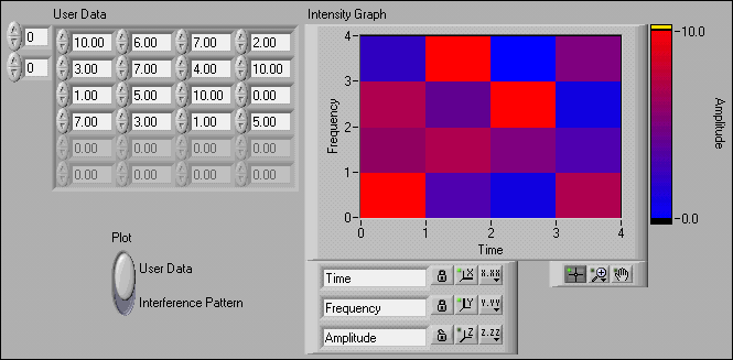
Alignment of cells WPF graphics intensity
I'm used to seeing graphs like this (found on internet)... where the first cell is the same size as the others:
But in my case I have this... cells where data for some aligned reason with numbering Center brands. As a result, the edge squares are only half of the other places (red squares show this issue). Is this a setting any? It's a simple table 6 x 6. Thank you!
The short answer is that you can specify an AxisDouble for the HorizontalAxis and VerticalAxis of your graph of the current see the Visual range complete the data :
The longer answer is that intensity WPF chart displays values of data centered around their point of origin. This improves the interaction with other components, such as cursors and annotations. Unfortunately, even if we have improved the use of
doubleaxes in charts able Studio 2015, we left the default axis of the graph of the intensity as typeint(I created a task to fix this for the next version). -
WPF graphics export to image problem
My problem is that I created a new custom personalized using the chart wpf OR as a base. The control includes mainly the chart, its axis and legends on a grid. To allow the legend be moved, I put it in a grid of the child. My problem is that he was trying to export as an image control, I use the code below (similar to wpf graphical image export):
Rect bounds = LayoutInformation.GetLayoutSlot(MainGrid);
var bitmap = new RenderTargetBitmap((int)bounds.Width + 1, (int)bounds.Height + 1, 96, 96, PixelFormats.Default);
bitmap.Render(MainGrid);
My problem is the axes and the edges of the image exported to the Clipboard is dark as shown below. Is saved in the image, the edges are quite transparent but better (not visible in the photos app but visible in the paint). My question is why is this behavior and how can it be avoided?
Thank you.
The problem is the default color of the grid or niGraph in WPF is transparent. I simply changed color or image now saved correctly.
-
How to make the button to set the properties of auto-scale one of the Axes on the graphical indicator so I can turn on or off when I press on it.
I need to change the adjustment vaguely Autoscale property for my graphic indicator. Can someone help me please.
Thank you!
Hello
I have confirmed that there is currently no way programmatically enable/disable autoscaling for axes on the LabVIEW graphical indicator generator of the user Web interface. We noted this to possibly be implemented in the future; Sorry for the inconvenience.
Maybe you are looking for
-
How can I show pictures from a pc on Apple TV 4
Is it possible that I can use Apple TV 4 to view photos on a similar PC how to use the photos on Mac program
-
For 7.0, get popup saying "cannot load XRE extensions." Firefox does not open.
The Win 7 system, loaded the new version 7.0 of Firefox. When you try to open Firefox, I get a popup to say that 'could not load XRE functions." Firefox does not open.
-
Adapter for L450-136 wireless satellite not appearing is not in the network adapter
My laptop has been upgraded from Vista to Windows 7, and the wireless adapter does not appear in Device Manager. I don't know what type of card is or how to find out and any software or driver that I am trying to install can not find anything. I trie
-
HP G - 72 Video driver UPDATE (ATI Mobility Radeon HD 5470)
Hello... Means, I need the latest driver for my Ati Mobility Radeon GPU 5470... win7 64 bit I found only the driver of 2010 (sp 50231) and I need the latest... When I download for example 13.9 catalyst... with graphics driver and install, graphics sw
-
Replaced the HARD drive on N5010, put in "Windows Boot Manager" error
I'm having N5010 and installed the new Seagate hdd. I used the dell recovery disk (created when the system has increased with the old hard drive) for installed Windows 7 and all the software came as part of the original image. After successful instal