How the ND_SCANCLK_LINE signal used in DAQmx? It is complete Hold event?
I have moved an old application (using the PCI-6013-OR map) to DAQmx recently, but have some difficulty working. When starting, the signals are configured as shown below.
Select_Signal (1, ND_PFI_2, ND_IN_CONVERT, ND_HIGH_TO_LOW);
Select_Signal (1, ND_SCANCLK_LINE, ND_SCANCLK, ND_LOW_TO_HIGH);
I've done the migration as shown below.
Select_Signal (1, ND_PFI_2, ND_IN_CONVERT, ND_HIGH_TO_LOW);
DAQmxExportSignal (TaskHandle, DAQmx_Val_AIConvertClock, "/ Dev1/PFI2");
DAQmxSetAIConvActiveEdge (TaskHandle, DAQmx_Val_Falling);
Select_Signal (1, ND_SCANCLK_LINE, ND_SCANCLK, ND_LOW_TO_HIGH);
DAQmxExportSignal (TaskHandle, DAQmx_Val_AIHoldCmpltEvent, "/ Dev1/AIHoldComplete");
DAQmxSetExportedAIHoldCmpltEventPulsePolarity (TaskHandle, DAQmx_Val_ActiveHigh);
But my application displays the data in the form of two samples shifted left. I guess that the acquisition has been delayed.
I do correct migration or is there something different in the DAQmx?
Documentation OR that I get confused whether ND_SCANCLK_LINE or AIHoldCmpltEvent sample clock. Or is this sample clock?
What is the SCANCLK Signal, and how to use it?
Hope this helps
Tags: NI Hardware
Similar Questions
-
It would be great to see how the various color schemes are used, for example, if I use someones colors for a Web site design, it would be great to inform the designer of the regime and also other kuler users. Perhaps we could have a forum just for where links can be displayed?
It's a good idea! For now, use the comments to connect work and theme...
Saami -
How can I activate several tensions trigger on the PCI-6221 using NOR-DAQmx?
I use the card to make an acquisition of data simple PCI-6221. The idea is to allow three different analogue voltages trigger the State of data acquisition. I currently put code in place for a trigger voltage but I'm not sure what to do to add two additional trigger voltages. Any ideas?
Thank you.
Hi capncane,
The 6221 is not able to do an analog trigger so DAQmxCfgAnlgEdgeStartTrig will not work for your card. Is your relaxation a digital signal? If so what kind of logic level is? If it's TTL, you can use the PFI lines. If this isn't the case, you need to trigger as I mentioned in my previous post.
-
How the input signal updated step in simulation?
Hello
I have my own model of transfer function. I did first with Matlab/Simulink simulation and succeeded. I use the Signal Generator in Simulink to get out my custom step signal. I modified my step so signal to:
t = 0 y = 0
t = 0.1 y = 0
t = 0.1 y = 50
t = 10, y = 50
t = 10 y = 65
t = 30 y = 65.It's the kind of staircase input signals. Now, how to build such this approach custom signals to be fed in my transfer function. I tried the function 'Not of Signal' of the 'Simulation', but I can only get the 50 and I don't know how to add more "staircase" in my input signals. Could someone help me?
-
How to generate signals using NI - HSDIO.
Hello
I need to create two signals different pulse square. I don't know how to set their frequencies, number of cycles and FRP using NOR-HSDIO.
Thank you!!
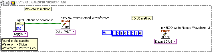
You must create a set of data to send to the HSDIO. It only builds what you send to it. Suppose you want to produce a square on one channel wave. Implement the HSDIO for right channel, trigger, timing, etc. Look at the function HSDIO write nominated Waveform. It says name of waveform, but you can use the polymorphic selector (the area under the function) to select other types of data outside of the waveform, i.e. a table 1 d of numeric (U32, U16, etc.). You must create an arry of data that would be akin to a square wave. Or you could use the input waveform and create a square wave.
The simplest is the waveform because Labview waveform generator functions available. See the image below. If you want to use table 1 d, construct you a table or alternation of 1 and 0 to produce a square wave. The image below is only a partial code. Need to add the rest of the installation HSDIO functions.
-
Hello
I'm following link below to show/hide my columns dynamically. See "formatting of column.
http://docs.Oracle.com/CD/E12844_01/doc/BIP.1013/e12187.PDF
According to the doc element can be made in private/public.
<items type="PUBLIC">
 <item>
  <name>Plasma TV</name>
  <quantity>10</quantity>
  <price>4000</price>
 </item>
 <item>
And even can be used to hide the column with the help of State
<?if@column:/items/@type="PUBLIC"?>
MY QUESTION IS HOW TO DO THIS IN MY XML BELOW?
Here's the part of my XML code that I use in the definition of the data to RTF.
<group name="GH3" source="QH3">
<element name="COLUMN_HEAD3" value="COLUMN_NAME" />
</group>
<group name="GH4" source="QH4">
<element name="COLUMN_HEAD4" value="COLUMN_NAME" />
</group>
I'm out like that.
<LIST_GH3>
<GH3>
<COLUMN_HEAD3>REBILL_TO_OTHER_BUSINESS_UNIT</COLUMN_HEAD3>
</GH3>
</LIST_GH3>
<LIST_GH4>
<GH4>
<COLUMN_HEAD4>XYZ</COLUMN_HEAD4>
</GH4>
</LIST_GH4>
In order to use the logic according to the oracle document I want output like this.
<LIST_GH3 type="PUBLIC">
<GH3>
<COLUMN_HEAD3>REBILL_TO_OTHER_BUSINESS_UNIT</COLUMN_HEAD3>
</GH3>
</LIST_GH3>
<LIST_GH4 type="PRIVATE">
<GH4>
<COLUMN_HEAD4>BLANK</COLUMN_HEAD4>
</GH4>
</LIST_GH4>
Should what changes I make in my XML to get the result of the execution as above? Help, please. Where should I make changes in the XML above? Name of the Group? Name of the element?
I intend to use it under condition in RTF model to hide the column, but do not know how to set the column as PRIVATE/PUBLIC type in the XML output that is used to populate the data in the RTF while running.
<?if@column:/BTSPIEXP/LIST_GH3/@type=”PUBLIC”?>COLUMN_HEAD3<?end if?>
Kind regards
Patricia K.
Hello
Problem has been resolved. I used the value of the item to determine whether to show it.
Kind regards
Patricia K.
-
How the packaging material used to represent the packaging material
Hello
We use PLM 6.0 and upgrade to PLM 6.2. but we have trouble on the specifications for packaging printed have been deprecated.
In the user's Guide for the hardware specification packaging should be used to represent printed packaging.
Can it-someone ' a please us referring to this problem.
Thank you
Sorry, it should be 3.13.1. I don't think that it's mentioned in the documentation since it was released two months ago.
You can contact Oracle support for help. The bug number is 22253870.
-
I have trouble understanding how the calendar for the vi simulate Signal Express. Can anyone help?
I'm generating a signal to 100,000 samples per second. The frequency is 4 Hz. I then pass the signal through the basic vi trigger detection to find out where the wave crosses 0.5.
Since the signal is 4 Hz, the waveform should cross 0.5 each 0.25 sec. However, when I created a table of the times that the trigger is activated, it is not 0.25 seconds.
I don't know if there is a problem with my calculation of the duration of simulation, or if I don't understand how the vi signal simulation works. Thank you very much for your ideas!
Yes, you made a few mistakes or bad assumptions about who express vi.
The frequency is 4 Hz samples per second is of 100,000 samples (orders of magnatude) generated too high are 76 (0.76mSecs worth of data). 1% duty cycle so a transition product only once every thousand loops! 1315 or 1316 loops between L - H transition to be more precise
Try
40 s/s
40Samples (a seconds of data)
right to 50%
-
How does the predator AG3 used together the 128 GB ssd and hard drive 2 TB
I am considering buying a predator AG3 at Costco. It comes with a 2 TB HDD and ssd 128 b. How the system is used both in combination? The ssd is only for boot? Windows will be on the SSD. The system will know to go on the HARD disk for programs not on the SSD drive? I have no experience using a system with two disks of a different type.
SSD is usually used as installation of the OS and some heavy load programs (editing - audio - video)
HARD drive is used as data storage or install programs of large size (for most games).
System does not know where you want to install it that way, he asks during installation
example of
C:\Program Files\gamenameXYZ
You can tell the installer to use instead of C: on SSD HARD drive, so you will change from C to D (if your HARD drive is D: letter of the system)
D:\Program Files\gamenameXYZ
-
How to calculate the total memory used by oracle under Linux?
Hi all
In one of my server have 148 GB of total physical memory and 12 databases are running. For capacity planning, I need to know how the Oracle server use.
How to calculate the use oracle database? I was perplexed because Yop out his show off 148 gb 128 GB are used.
Below for your reference:
++++++++++++++++++++
== > back to top
top - 09:52:32 up to 151 days, 15:20, 3 users, load average: 6.11, 6.00 6.05
Tasks: 7 running, 1314, 1321 total sleep, stopped 0, 0 zombie
CPU: 37.8%us, 1.4%sy, 0.0%ni, 55.0%id, 5.6%wa, 0.1%hi, 0.2%si, 0.0%st
MEM: 148290444 k total, 129368792 k used, 18921652 k free, 1450292 k buffers
Swap: 50331632 k total, 1296188 k used, 49035444 k free, 114733336 k cached
The memory allocated to each instance is: sga total == > 34 pga = > 48 GB gb
+++++++++++++++++++++++++++++
SGA PGA
4 GB 4 gb
4 GB 4 gb
2 GB, 4 GB
2 GB, 4 GB
2 GB, 4 GB
2 GB, 4 GB
2 GB, 4 GB
3 gb 4 gb
3 gb 4 gb
4 GB 4 gb
3 gb 4 gb
3 gb 4 gb
Thank youTry this - http://www.pythian.com/news/29703/oracle-instance-memory-usage/ for each of your instances.
As far as I know, different instances may share only the binary code oracle and using libraries, so you should be able to easily understand the amount of memory of all instances of 12.
Lordane Iotzov
http://iiotzov.WordPress.com/ -
How to perform deconvolution using FFT
Hello everyone
Is there anyone who knows the algorith or can give me a vi that shows how to perform deconvolution of the two functions by using the FFT. Using labview for deconvolution, the suggested algorith is.
- Calculate the Fourier transform of the input sequence X * Y.
- Calculate the Fourier transform of the input sequence Y.
- Divide the Fourier transform of X * Y by the Fourier transform of is. Call the new h sequence.
- Calculate the inverse of Fourier of h to get the deconvolved Xsequence.
I tried to do e same but did not work. I enclose a Vi in first, I bypassed a pulse-to-pulse-triangular square. Then I deconvolutee the convoluted signal using a triangular pulse with deconvolution tool in labview. Then, I tried to do the deconvoltion using the FFT algorith but did not work. Y at - it someone who has an idea on how to perform deconvolution using FFT.
Regrads
Charles
Hi Charles,
It should work to 8.5. Let us know if you still hurt to open it.
-Greg J
-
How to control the mouse cursor using EEG signals
Hello world
I am doing a project of cursor control using EEG signals. The idea is to find a way to all signals in a specific period of time in order to find the signal Ridge. Then, the highlight will be a parameter to control the position of a cursor.
Can someone tell me the function that allows you to control the mouse cursor?
I also found an old topic asking about it (http://forums.ni.com/t5/LabVIEW/Moving-Mouse-using-Labview/td-p/1285842) and I run an example of this link ( smercurio_fc) program. My cursor is stuck in the upper left corner of the screen, I can't control it again. Can you tell me how to run this program and to use the windows API?
Thank you in advance.
Sorry, but I can't do it for you.
As I advised, you should take the free online tutorials. You clearly lacks the basic concepts of LabVIEW, as data flow.
Things more: in your real applicaton does not use DAQ Assistant, screw Express are generally not optimal for data acquisition. It is safer and better use good DAQmx live. What is the equipment you use? Sampling rate, etc.?
Why do you need to read data files? For testing? I thought that you will acquire data active, right? In your VI generate you some signals and write in a data file. Is this also for testing?
There are several constructs in your VI which simply don't make sense.
So again, I really suggest to go through online Core1-2 teaching material, which is accessible if you are a student, or if you have shared services provider license... It will really help.
-
How can I use the USRP to record a signal using its two RX ports simultaneously?
Hello.
I am trying to record a signal using two antenna cone. The reason that I need two antenna to cover the bandwidth (DC - 6 GHz). a single antenna covers DC - 300 MHz and the other covers 300 MHz to 6 GHz. so I need to use two RX port of USRP at the same time to record the signal. I have two questions:
1. is this all USRP market capable of covering this frequency range?
2. is it possible to use the two RX port at the same time to the signals of the records I described? If this is not the case, how can do?
P.S. I have two NI2920 USRPs and two USRPs N210 in my lab.
Thanks in advance for your time.
Sam.
Hi Sam,
To answer your first question, the USRPs you can reach the bandwidth you want. There is not a USRP, to my knowledge, that can reach this range in a single device.
Also note that you can only use RX convened for two different ports at the same time using LabVIEW and the pilot of the USRP. If you want to use the two lines of RX, you will need to run a session with a single line, close the session and then start a different session for your second RX line.
-
Problem updating my state machine, using the emg signal
Hello
I have problems with my code. My entry is an EMG signal that I gather from three different electrodes using usb 6008. In the program, I divide the signals and display them in a chart that is unique. What I want now is to read the signal, and if a signal passes a threshold I want an LED lights. This must remain lit until there is another signal that passes the threshold.
To put it simply: "large enough signal--> lamp on--> stay informed--> enough large signal--> lamp--> stay off the coast and then start again."
I tried a few different approaches, but I decided using a state machine. Now, the problem is that when the signal to enter the state machine the program crashes. I think it's because the table that I use to convert the signals does not update when I get my state machine, so the signal stops to come. But how to get around this problem? It is even possible to code what I want?
I have attached the code. All the tips are welcome, I have been struggling with this for some time now.
Thank you
jenmich
The problem is internal while the loop is run until the stop condition is true, but he never does a new Boolean entry. So that it remains for always in the same State. Remove the inner loop and put the shift register on the outer loop instead.
You must also use a daqmx configures the element, and then set the properties of daq. The read.vi can be set to read a number of samples of each iteration.
Also: you can expand the table to index for several items of output. If you want that element number 0, 1, and 2, you have yet to wire the index entries

-
How to choose destinations for counter/timer signals in NOR-DAQmx?
In the document M Series DAQ
M series user manual
622 x, NI 625 x and the materials NOR x 628
M series user manual
July 2008
371022K - 01appears on page 7-30:
Counter/Timer default pinout
By default, NEITHER-DAQmx routes counters/timers and outputs inputs to the PFI pin, shown in table 7-4.
Table 7-4. 68 peripheral pins by default Counter/Timer pines NOR-DAQmx
Counters/timers fail-safety connector 0 PIN (name)
0 2 CTR (PFI 12)You can use these default settings or select other sources and destinations for the
counters/timers of NOR-DAQmx signals. Refer to the connection counter signals
in the NOR-DAQmx help or the help of LabVIEW in version 8.0 or later for
more information on how to connect your signals for common counter
measures and generations.I couldn't find any hint to the appropriate command of DAQmx in the "NOR-DAQmx C reference Help" to select other destinations for counter/timer signals in NOR-DAQmx.
Please can you tell me the DAQmx command right? Thank you very much.
I use the NI USB-6259 M material Series DAQ, BNC end unit.datafriend,
If I remember correctly, you can "free" the output terminal of default counter by calling DAQmxSetCOPulseTerm and passing an empty string in the 'data '.
Hope that helps,
Dan
Edit: You can also set this to any other valid terminal (IE... "Dev1/PFI0") and to send the output to.
Maybe you are looking for
-
A few days ago TextEdit has started planting immediately after that I try to start it. It does not matter that I have click the icon or click on a text file. It crashes immediately and opens the accident report. Reopen repeats just the process of the
-
NB100: battery discharges in hibernation mode
Now that my hibernation function works OK, I used most of the time, I let the netbook.So it is faster to recover after hibernation that restart. But I notice that landfill of battery substantially; It is usually on the critical alarm level after some
-
Computer of my computer fan runs constantly?
My computer is a HP Pavilion dv4-1123us Entertainment Notebook Pc. whenever I use any program that increases computer around 40% CPU usage, the fan begins to operate constantly a little noise to very loud noise. I thought that its caused by a program
-
Where can I find my new hp laptop laptop system software and recovery to open their Web site?
Where can I find my new hp laptop laptop system software and recovery to open their Web site? 1. I have install the hp bios system update and failed. 2. the beginning of HP ENVY 17 laptop u011nr - displays the message "something wrong." 3. then I do
-
Spider Solitaire on Windows XP has been removed. How can I reinstall?
My Windows XP system has Spider Solitaire. Now, it's gone! How can I reinstall it? I can't find any link on the Microsoft web page where I can download...