How to generate signals using NI - HSDIO.
Hello
I need to create two signals different pulse square. I don't know how to set their frequencies, number of cycles and FRP using NOR-HSDIO.
Thank you!!
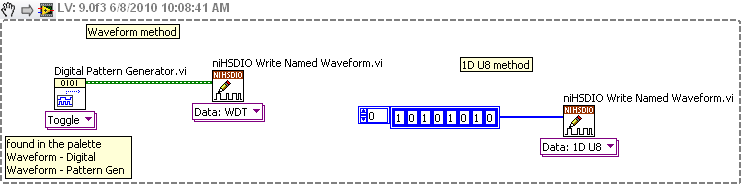
You must create a set of data to send to the HSDIO. It only builds what you send to it. Suppose you want to produce a square on one channel wave. Implement the HSDIO for right channel, trigger, timing, etc. Look at the function HSDIO write nominated Waveform. It says name of waveform, but you can use the polymorphic selector (the area under the function) to select other types of data outside of the waveform, i.e. a table 1 d of numeric (U32, U16, etc.). You must create an arry of data that would be akin to a square wave. Or you could use the input waveform and create a square wave.
The simplest is the waveform because Labview waveform generator functions available. See the image below. If you want to use table 1 d, construct you a table or alternation of 1 and 0 to produce a square wave. The image below is only a partial code. Need to add the rest of the installation HSDIO functions.
Tags: NI Software
Similar Questions
-
Hello
I want to generate signals with my USB-6211 from a prepared file in advance, so I have a file full of sampling points and you want to generate a signal with this file. The file can achieve big enough. So I need to find a way to partially fill the generator with samples...?
Anyone?
Best regards
Thijs
Hello Thijs,
What file do you use? Excel? TDMS? txt? or others?
I guess you wrote your samples in a normal txt file.
To do this, you can read in your worksheet (if its only data without columns, which are not serious) you can use the worksheet File.vi reading
This VI reads all the data that you specify (how many lines, shift etc.) after that, you can simply set your table with the normal array functions and give these data
to your task AO.
Let me know if this was helpful, or if you would like more information.
Kind regards
Markus
-
How the ND_SCANCLK_LINE signal used in DAQmx? It is complete Hold event?
I have moved an old application (using the PCI-6013-OR map) to DAQmx recently, but have some difficulty working. When starting, the signals are configured as shown below.
Select_Signal (1, ND_PFI_2, ND_IN_CONVERT, ND_HIGH_TO_LOW);
Select_Signal (1, ND_SCANCLK_LINE, ND_SCANCLK, ND_LOW_TO_HIGH);I've done the migration as shown below.
Select_Signal (1, ND_PFI_2, ND_IN_CONVERT, ND_HIGH_TO_LOW);
DAQmxExportSignal (TaskHandle, DAQmx_Val_AIConvertClock, "/ Dev1/PFI2");
DAQmxSetAIConvActiveEdge (TaskHandle, DAQmx_Val_Falling);Select_Signal (1, ND_SCANCLK_LINE, ND_SCANCLK, ND_LOW_TO_HIGH);
DAQmxExportSignal (TaskHandle, DAQmx_Val_AIHoldCmpltEvent, "/ Dev1/AIHoldComplete");
DAQmxSetExportedAIHoldCmpltEventPulsePolarity (TaskHandle, DAQmx_Val_ActiveHigh);But my application displays the data in the form of two samples shifted left. I guess that the acquisition has been delayed.
I do correct migration or is there something different in the DAQmx?Documentation OR that I get confused whether ND_SCANCLK_LINE or AIHoldCmpltEvent sample clock. Or is this sample clock?
What is the SCANCLK Signal, and how to use it?
Hope this helps
-
OR PCI-6542: Creation of dynamic waveforms using the HSDIO library
Hello!
I have problems to understand how to create waveforms using the HSDIO library to run on a card PCI-6542. I need to create a program that activates a channel for 12.5 microseconds, waiting for a while (i.e. 100 samples) and activates another channel to 12.5 microseconds.
This program must be used in a Multielement ultrasound system.
Here the example of dynamic generation program that transforms the channels 0-2 on 1024 samples.
/************************************************************************
*
* Example program:
* DynamicGeneration.c
*
* Description:
* Generates a simple model on the specified channel.
*
* Pin connection information:
* None.
*
************************************************************************// * Includes * /.
#include "niHSDIO.h"./ * Sets * /.
#define WAVEFORM_SIZE 1024int main (void)
{
ViRsrc deviceID = 'Dev1 ';
ViConstString channelList = "0-2";
ViReal64 sampleClockRate = 50.0e6;
DataWidth ViInt32 = 4;ViUInt32 waveformDataU32 [WAVEFORM_SIZE];
ViConstString waveformName = "myWfm";
ViInt32 timeout = 10000; / * milliseconds * /.ViSession vi = VI_NULL;
Error ViStatus = VI_SUCCESS;
Bruno errDesc [1024];
ViInt32 i;/ * Initialize generation session * /.
checkErr (niHSDIO_InitGenerationSession)
Deviceid, VI_FALSE, VI_FALSE, VI_NULL, &vi));/ * Assign channels for dynamic generation * /.
checkErr (niHSDIO_AssignDynamicChannels (vi, channelList));/ * Set up the clock sample parameters * /.
checkErr (niHSDIO_ConfigureSampleClock)
VI, NIHSDIO_VAL_ON_BOARD_CLOCK_STR, sampleClockRate));/ * Query the data Width attribute * /.
checkErr (niHSDIO_GetAttributeViInt32)
VI, VI_NULL, NIHSDIO_ATTR_DATA_WIDTH, & dataWidth));
/ * Fill the waveform with ramp data * /.
< waveform_size;="">
{
waveformDataU32 [i] = i;
}checkErr (niHSDIO_WriteNamedWaveformU32)
VI, waveformName, WAVEFORM_SIZE, waveformDataU32));/ * Start the generation * /.
checkErr (niHSDIO_Initiate (vi));/ * Wait for all the generation * /.
checkErr (niHSDIO_WaitUntilDone (vi, timeout));Error:
If (error is VI_SUCCESS)
{
/ * Print result * /.
printf ("made without error. \n") ;
}
on the other
{
/ * Get the description of the error and print * /.
niHSDIO_GetError (vi, & error, sizeof (errDesc) /sizeof (petitioner), errDesc);printf ("\nError encountered\n===\n%s\n", errDesc);
}/ * log * /.
niHSDIO_close (vi);/ * prompt to go out (for the popup console windows) * /.
to continue...\n");
GetChar ();error return;
}Issues related to the:
How can I change the values in waveformDataU32 to create market reports (instead of just always on)?
How to select the channel waveformDataU32 is applied to the?
Thank you!
Zachary Geier
The waveformDataU32 table is an array of 32-bit integers. Each bit corresponds to a line on the device. On the first clock cycle, this program outputs:
0000 0000 0000 0000 0000 0000 0000 0000
Then it displays the following, changing at each clock Pulse:
0000 0000 0000 0000 0000 0000 0000 0001,
0000 0000 0000 0000 0000 0000 0000 0010,
...
and so on all the way up to 1023:
0000 0000 0000 0000 00000011 1111 1111
In the example that you include at the bottom, you set the least significant bit (LSB) to zero and one, actually only change one line on the output. To change all the lines, you must instead use 4 294 967 295 or 0xFFFFFFFF:
< waveform_size;="">

     < 200){="" if="" sample="" number="" is="" less="" than="">

          waveformDataU32 [i] = 0;     Disable channels 0-2

     }

     else {}

          waveformDataU32 [i] = 4 294 967 295;     Otherwise turn on all channels to 800 samples

     }

} -
How to build and use a clock for triggering signal internal.
Hi all
Please excuse my ignorance, but I have been assigned to programming a system/operation of data collection for the experience, I'm trying and have no idea where to start. My goal is to generate a clock signal 0 - 5V with a frequency on the front panel user control and use the signal to trigger events internally. As for the output, I need to control a port analog and digital. The two channels should output a pulse of user specified width to a user specified delay each of each rising edge of the clock signal. The only difference between the two is that I need to specify the output voltage to the analog port.
If someone could offer some guidance as to the best way to do it, would be great! Thanks in advance!
HI C-N-O,.
Will what equipment you use? You have access to a way out of meter? If you do, here's a hat example shows you how to generate a continuous pulse DAQmx screws Train (if you are using National Instruments hardware, otherwise you could check if there is a driver available for your device):
Community: Generate continuous pulse Train
https://decibel.NI.com/content/docs/doc-12164Alternatively, you can start by looking at the examples of DAQmx, to see some details of the analog and digital control.
(if you have the driver already installed, you can look for them under LabVIEW--> help-> find examples-> browse-> hardware input and output-> DAQmx)
Kind regards
Caroline
-
How can I use the USRP to record a signal using its two RX ports simultaneously?
Hello.
I am trying to record a signal using two antenna cone. The reason that I need two antenna to cover the bandwidth (DC - 6 GHz). a single antenna covers DC - 300 MHz and the other covers 300 MHz to 6 GHz. so I need to use two RX port of USRP at the same time to record the signal. I have two questions:
1. is this all USRP market capable of covering this frequency range?
2. is it possible to use the two RX port at the same time to the signals of the records I described? If this is not the case, how can do?
P.S. I have two NI2920 USRPs and two USRPs N210 in my lab.
Thanks in advance for your time.
Sam.
Hi Sam,
To answer your first question, the USRPs you can reach the bandwidth you want. There is not a USRP, to my knowledge, that can reach this range in a single device.
Also note that you can only use RX convened for two different ports at the same time using LabVIEW and the pilot of the USRP. If you want to use the two lines of RX, you will need to run a session with a single line, close the session and then start a different session for your second RX line.
-
How to generate a pulse signal?
Hello
I'm relatively new to LabVIEW and I need to generate an impulse (Dirac function) in the motor continuous. At the same time, I need to be able to change the pulse width.
I am currently using LabVIEW 7.1.
Hey,.
With your E-Series cards, you can counter to generate impulses for the user.
The best way to find examples using the Finder example under the Help menu of LabVIEW. Simply navigate to the e/s material > DAQmx > Counter > generate signals or search for pulse generation.
-
How to generate the alert when pageitem move on the page? and what class boss be use to move pageitem
Hi Philippe,.
You can see the kDocBoss for the ClassID with the PMIID IID_ITRANSFORM_DOCUMENT kLocationChangedMessage.
Markus
-
How to generate XML nested using PL/SQL data?
I have an XML that looks like this file...
<? XML version = "1.0"? >
< TDefs >
< ListItem >
< TDef >
< DisplayName > AFP < / DisplayName >
< enabled > True < / enabled >
< LISName > AFP < / LISName >
< LOINC / >
< PrintName > AFP < / PrintName >
< CompatibilityCode > 1 < / CompatibilityCode >
< details >
< PatientReplicates > 1 < / PatientReplicates >
< AutoReDilute > false < / AutoReDilute >
< / details >
< DilutionList >
< TDefDilution >
< dilution > 1 < / Dilution >
< CalculationFactor > 1 < / CalculationFactor >
< / TDefDilution >
< / DilutionList >
< TDefRange >
< RangeList >
< RangeInfo >
< ID >
< int > 6509 < / int >
< /ID >
< name >
< string > check Range2 < / string >
< / name >
< Name_MessageID >
< int >-1 < / int >
< / Name_MessageID >
< IsNull RepeatedlyReactiveData = "true" / >
< IsNull RepeatedlyReactiveComments = "true" / >
< CreatedByIM >
< Boolean > true < / Boolean >
< / CreatedByIM >
< / RangeInfo >
This is data that are from different tables. It is a multilevel nested nodes each other.
How do I achieve using PL/SQL? What is the best way?
I've only used to date dbms_xmlgen to generate data from a single table.
Can anyone help?How do I achieve using PL/SQL? What is the best way?
SQL/XML functions.
For example: {message identifier: = 9670705}
After a few data structures and table (DDL) samples if you need specific help on the query.
-
How to generate the password encoded using agent in ODI?
Hello
I've created a scenario and I plan to them. Now, I want to create an autonomous agent to run this scenario. To do this, I update odiparams.bat file where I am mentioning the details of the repository. I want to generate the encoded password repository connection using batch processing utility officer. After you type following command at the command prompt in windows xp:
agent to encode the password
Failure of the sound connection password invalid username error display.
What should do? How to generate the password encoded using batch agent utility?
Thank you
Shrinivas
Published by: Shrinivas Dayma on 13 Aug 2011 02:03Hi Shrinivas,
This command is for ODI 10 g.
For 11g,.
Encode
Thank you
Guru -
Best way to generate signals of activation (square wave) with my 9401 on my 9022?
Hi, I tried seriously over the past two days to find the best way to do it. I am trying to generate a very precise square wave, controlling the duty cycle and frequency, with the OID on the 9401 in testbed cRIO 9022.
I have a VI that is theoretically able to do this, but whenever I try to go above 5 Hz or more, duty cycle and frequency becomes inaccurate (I have watch on an oscilloscope), various a lot too for my needs. I have a feeling that this is caused by my addiction on the calendar software controlled, with errors at the time (of the ms order) accumulate as they get processed and the signal is sent. I have attached a piece of code that illustrates the basic idea of what my VI have in them.
I have avoided the square wave generators integrated because I could never work to satisfaction, but I can work with them so that will solve my problems. Selection structures and cases prevent the user to exaggerate their inputs. Unwaited so the loop was just to test.
I'm running the 9022 as target in real time, but also tried to run in the FPGA and I was able to produce much more accurate signals using FPGA VI square wave, displaying a Boolean variable, but I couldn't see the best way to get double precision variables to work with everything (and I want more precision than variables FXP enabled clock 40 MHz).
I feel there is just a mistake in my approach here. I've seen other discussions where people throw around using meters to edge of the test bench to produce a square wave, and I see the example screws as Gen dig pulse - continuous Train, I'm not sure if initially these screws DAQmx for my situation (eg. How to identify my counters, because they are clearly not Dev1/ctr0 by default in these examples)
Thank you
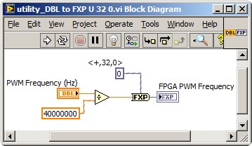
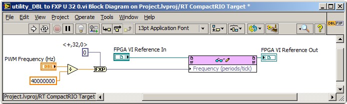
Dealing with the representation of Point fixed and all is a reality for LabVIEW FPGA<= 2011="" programmers.="" you="" might="" build="" a="" small="" sub="" vi,="" such="" as="" the="" one="" attached,="" to="" encapsulate="" the="" frequency="" calculation,="" thereby="" abstracting="" the="" conversion="" formula="" and="" fixed="" point="" data="" type.="" you="" can="" adjust="" the="" properties="" of="" the="" floating="" point="" input="" control="" to="" accept="" only="" valid="">
This implies the series VI void on the host of the RT, and not on the FPGA target. So, you also need nodes in the Palette of the FPGA Interface to send PWM fixed Point RT frequency to the FPGA. The complete solution of frequency may resemble the following. It is common for FPGA programmers to build a collection of thesesub screw, that make up the API for hardware.
Note that 40 MHz is hard-coded. For increased flexibility, consider making the FPGA clock rate an entry to the Subvi with a default value of 40 MHz.
-Steve
-
How to generate an impulse to test short circuit in an inducer
Hello
IM new to labview and am in need of complete SURG - SURGE STRESS TEST
This test is intended to detect a short tour inter by applying a number of high
voltage pulses (or surge) for the selected winding.
Each pulse should produce one sinusoidal transient that eventually decreases to zero.How to generate the impulse using labview.
Hi Jessica,.
Please see the "pulse pattern.vi" function--> pallets of signal processing signal generation.
Otherwise, you can browse through examples of LabVIEW.
Kind regards
Srikrishna.J
-
PXI-6602 generate signals in squaring A, B with DAQmx in CVI
Hello
I want to know if it is possible to generate a quadrature encoder signals...
I want to generate the Signal A, then B Signal with a 90 ° of the delay on the other and be able to set the number of pulses that I want to generate.
I tried to generate signals with DAQmxCreateCOPulseChanFreq, but I can't start Singal B with the delay of 90 °.
Have any experience on this?
Thank you for your help,
Hello gramirezv Hello,.
Here is a KB which may help you to generate two trains of pulses with the same frequency but with a phase shift:
How can I generate two pulse Trains phases shifted from each other on my E series card?
http://digital.NI.com/public.nsf/allkb/26CCE4F74DACFD1886256DCF006B011A?OpenDocument
Have a lovely evening,
Best regards
CaEnOs
-
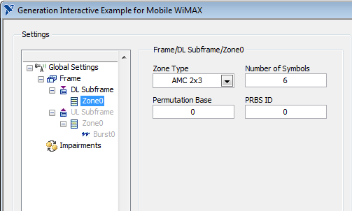
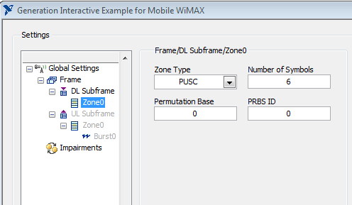
Hello.
I use a VST OR to generate the WiMAX signal. I installed NO measure costume for Mobile/Fixed WiMAX 1.0 on the calculation. But I can't find any option on the front panel of the combination of the generation to enable AMC or PUSC for generated signal. This feature exist at all?
Thank you.
Hello sam2013ni,
That's all I see for AMC and PUSC. Look in "box Type".
Best regards
-
How to generate a vector under LabVIEW?
How to generate a vector as n = 0:Ts:T in LabVIEW with the need for the mathscript node and with out of the loop?
Focus on the ramp VI model. It is located in the treatment-> Palette generation of Signal of the Signal.
Maybe you are looking for
-
Impossible to read while typing in form regions
I know how to change the color of the text, but all my forms have gray text in them and them does not affect the normal way to change the color of the text. I can barely see what I'm typing unless I click outside of the box, THEN it becomes dark gray
-
Satellite A210-171: need XP display driver
Hello I bought Equium A210 with Microsoft Windows Vista... I some how manage to get drivers Wireless LAN for XP but I don't know where to find the display drivers please someone tell me... Thanks a lot, I really need to do so much work and its just c
-
What is error code 8024400 was trying to auto updates?
I tried to load a MP3 Converter and it said I couldn't load it because I neede to update my Active X program. I went to Microsoft to make the Auto updates and I got the error above 8024400 was trying to make the updates.
-
How long should windows updates take after 5 months of Vista?
I have Windows Vista on a Toshiba laptop. A few days ago, I noticed that the last successful update was on 11/06/12. Then I ran windows update manually, but was getting an error that says "Windows Update cannot currently check for updates, because th
-
How to recover messages deleted from the hotmail Inbox
I deleted all e-mail messages by the mistakes of my Inbox on the 06July 2011. Is it possible to recover?