How to control NI 2503 PXI using labview?
Hello
I am vishal.
I have a job where I have to monitor the temperature of the various components.
LabVIEW platform is used to make a software that takes the output of thermistor through NI PXI 2503 multiplexer and converts it into digital
using or pxi5152 digitizer.now I have to control the two instruments of this and take values of the digitizer.
but the problem is that I don't know who you screw to control these instruments, because I do this first time.
I just know that the NIDAQmax screws can be used, but do not know how to use it.
Please give me a little early to make this program.
Thank you.
You can find this useful: combined with the switch Modules OR PXI high-speed digitizers measures. Basically, OR-Switch is used to control the multiplexer.
Tags: NI Software
Similar Questions
-
How to control an electric motor using LabVIEW?
Hello
is there a simple way to control the rotation speed of an electric motor (12V) using LabVIEW?
I have an idea how to achieve this using the card OR measurement, its not that cheap. Any ideas?
Maciek.
-
How to control the Planar scanner using labview
Hi, I am facing a control scanner Planar JSS project, the interface goes series use DB25 port, PM341UNIT and limit switch.
I don't have any ideas on how to start. Please I need support.
-
How to implement the wafer map using LabVIEW?
Hello LabVIEW Masters!
I have a project which includes control and searching for information on a PROBER. One of the difficulties I have now is how to implement a WAFER card using LabVIEW. According to the requirements of my client, the element of pads varies between 6 k and 23 k. I guess that do everything (a = a ctl/indicator led) will be a hell of a task, especially on how to effectively manipulate each elements. Does anyone have a better idea on the way whose that?
Please, I seriously need your help...

Thank you and best regards,
Dennis DG
Hi Dennis,
This wafer GerdW post card appears to me as a sort of histogram (for example http://www.ni.com/white-paper/4158/en#toc3);
Altenbach post well this example that shows how to use a plot of intensity to create a 2d histogram:
http://forums.NI.com/T5/LabVIEW/overlay-plots-as-intensity-graph/m-p/211222#M119248
Learn how it works and try to adapt it to your specific task.
Alex
-
How to control the mouse cursor using EEG signals
Hello world
I am doing a project of cursor control using EEG signals. The idea is to find a way to all signals in a specific period of time in order to find the signal Ridge. Then, the highlight will be a parameter to control the position of a cursor.
Can someone tell me the function that allows you to control the mouse cursor?
I also found an old topic asking about it (http://forums.ni.com/t5/LabVIEW/Moving-Mouse-using-Labview/td-p/1285842) and I run an example of this link ( smercurio_fc) program. My cursor is stuck in the upper left corner of the screen, I can't control it again. Can you tell me how to run this program and to use the windows API?
Thank you in advance.
Sorry, but I can't do it for you.
As I advised, you should take the free online tutorials. You clearly lacks the basic concepts of LabVIEW, as data flow.
Things more: in your real applicaton does not use DAQ Assistant, screw Express are generally not optimal for data acquisition. It is safer and better use good DAQmx live. What is the equipment you use? Sampling rate, etc.?
Why do you need to read data files? For testing? I thought that you will acquire data active, right? In your VI generate you some signals and write in a data file. Is this also for testing?
There are several constructs in your VI which simply don't make sense.
So again, I really suggest to go through online Core1-2 teaching material, which is accessible if you are a student, or if you have shared services provider license... It will really help.
-
How to control 2 motor epos using microcontroller 50/5
Hello. I did a program of integrated epos of labVIEW for control 1 motor epos. I make the program using the sub - vi from labVIEW epos data, but I don't know how to control 1 motor. Can anyone help me or tell me how to control 2 motors or wad is necessary? Thanks for your help :-D
Hi Spydi,
I don't think you need the CANopen library since you already use the instrument EPOS Driver.
Currently using a NI-CAN device to connect your controller? This is a device for both engines I think?
We are not very familiar with this set of drivers because it is not created by NOR, but I think all you have to do is to change the axis of entry to determine which engine is controlled.
So probably your first engine corresponds to the axis 0 (default value in the example program), then your second engine corresponds to the axis 1. When you want to send commands to the different engines, set the ID of node/keyhandle axis accordingly.
I hope this helps.
Best regards
Boon Chen
Applications Engineer OR
-
How to make the load simulator using labview 2010
I would like to ask how to load simulator using labview?
What have you tried so far? and exactly what your tying to do?
-
How can I control Sierra Instruments MFC using LabVIEW without the necessary drivers?
I am trying to program these MFCs with labview and it would be much easier with the drivers. I have chekced OR network driver and can't find anything. If anyone knows how to program controllers without drivers, or even better, if anyone knows where I can find the drivers, it would be much appreciated. Thanks in advance.
Sergio,
Check out these documents:
Development of instrument LabVIEW Plug-and-Play Drivers
Resources and development tools -
How to interface a simple way using LabVIEW 2009 simulink model and SIT?
Hello
I finally found a way to use a template simulink with LabVIEW and the Toolbox to SIT, but I'm not satisfied.
If you have any suggestions, the link of resource that I missed, please do not hesitate to answer
Note that I do not know much about simulink, so that is my question seems stupid, let me know what

Software configuration
OS: Windows (not an RT target)
LabVIEW 2009
SIT 2009
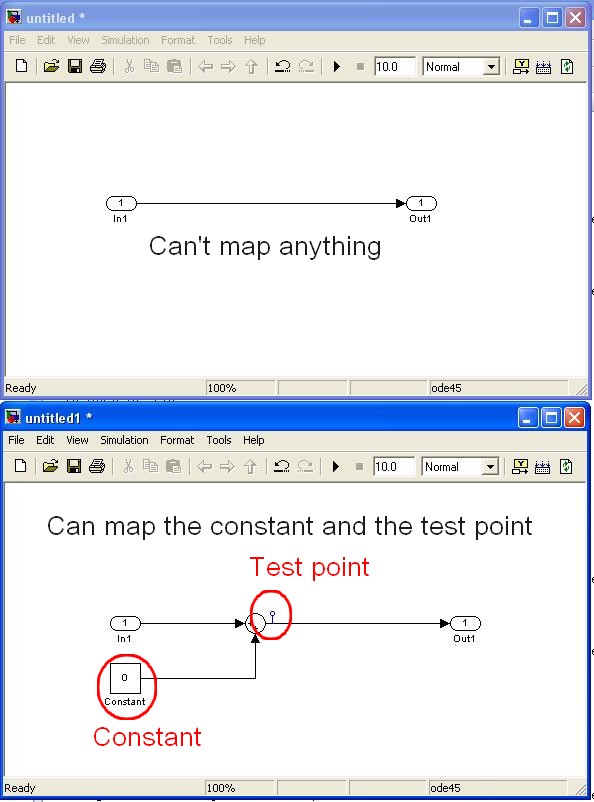
question 1: interfacing the model DLL (mapping considerations) with a driver VI
We have created a model of DLL by using the 'Workshop in real time' tab in simulink.
In LabVIEW, launch us the tool 'SIT connection manager' and try to use the DLL with a driver VI by mapping the e/s model for screw/lights orders.
The fact is that I fail to connect to my controls/indicators VI/o model because they do not appear in the mapping dialog box.
The simulink single objects that I managed to map are "constant" and "test points" while I need to edit the template simulink itself (example below)
Are in e/s model, not considered as part of the parameters of the model? (this could make sense because the mapping says in fact that it operates on "model parameters")
Is it possible to link the IO model VI commands/lights?
Note:
-the "configure HW i/o mapping" dialog box allows me to map model e/s with e/s HW...
-The examples also use these "constant" and "test points".
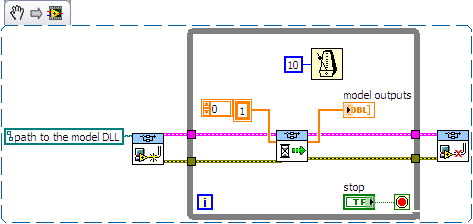
2nd question: use of direct screw SIT
I tried to use the DLL directly with the screws SIT (code example below)
This kind of code works well on another project (target of 8.0/RT LV) but not on the current project (LV 2009/Windows)
The second stage of the model never ends:
-0-index of the loop works as expected (model doing its job).
-index of the loop 1 starts normally, but execution is stuck in the 'SIT scheduler.vi.
Then I have no choice that to kill LabVIEW ("Reset screws" windows appear if I try to stop/close them).
Is there a reason that I do not see what explains this behavior?
Thanks for reading.
Any help appreciated.
Kind regards
Hello
I spent some time analyzing the VI driver as you suggested.
Here are my findings.
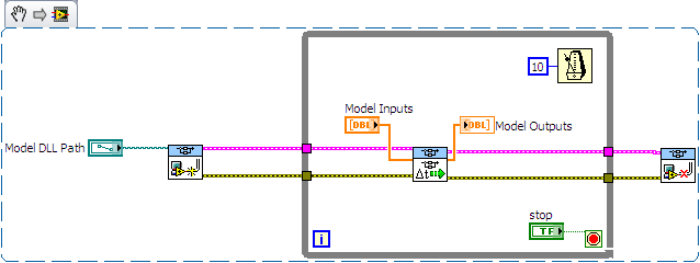
Question 1: the SIT connection manager does not pass to the model SW controls/indicators. Only, it allows the user map HW AIs/AOs.
The only solution I found (to have a SW - for example a shared variable - object that is mapped to an input/output model) is to customize the VI driver that is scripted by the SIT Connection Manager ("_Base
rate Loop.vi" in the flat sequence structure named "read code") Question 2: after spending some time in the VI driver, it seems that the VI to call right is not 'SIT scheduler.vi' but 'If SIT take model no time' (which uses the other as a Subvi)
My conclusions are correct? If I use the API in the wrong way, please let me know.
Kind regards
-
How to randomly choose excellent data using labview.
A very good day to all. I am currently working on a system that will be selecting whole number of together generated at random in number. If this is not possible, I would like to the system to be able to select the number of the set of numbers that have already been generated randomly from excel. kindly help me with the solution. To get clear, assuming I put numbers 1 to 10, I want a labview setup that will recover these numbers one after the other or with replacement without excel or auto generated. I know it's possible in matlab, but would prefer if possible labview. Thank you
More, otherwise all of the languages that I ran across were a rand() function returns a random number between 0 and 1. Get some other range belongs to the programmer. The usual method is to multiply by the beach, you need and add an offset to adjust the average. For example, if you need a random number between 200 and 300, the formula can present themselves as "rand () * 100 + 200". " If you need an integer, you can use the round function (who, it will remain as a float with no decimal pportion) or conversion (all). All this is feasible and direct in LabVIEW. Take a look: http://digital.ni.com/public.nsf/allkb/FCCDCD678EEF3A9186256D7B008054F5
If you feel more comfortable using a file, try this: http://digital.ni.com/public.nsf/allkb/C944B961B59516208625755A005955F2
-
How smooth a XY chart by using Labview 6i?
Hello
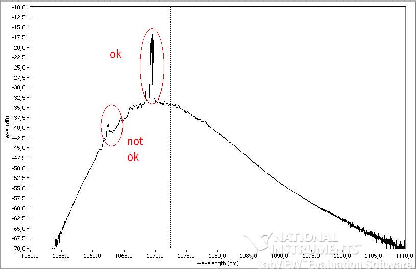
My main Vi captures the data that I sent to a XY graph
I would like to smooth out the curve before and after ('not ok' on the photo) the main peak ('ok' on the photo)
I looked for aboard or and have not found anything that I could use with Labview 6i
Does anyone have a solution?
Thanks in advance
See attached simple vi with data and graphics
There are several options:
- Use the filters in the range of Signal Processing to smooth the data.
- Fourier filtering techniques to smooth the data. Fourier transformations are also in the range of Signal Processing.
- Use almost any technical standard smoothing. To view the online version of the Numerical Recipes many methods. You will need C in LabVIEW, but it's pretty easy. Savitzky-Golay smoothing is especially good for this type of problem.
You will need to convert your XY data to waveform to get one of these at work. If you data are spaced regularly, it's pretty easy. If they are not, you will need to make some kind of interpolation. Or you can simply ignore the fact that you have unevenly sampled data, convert a waveform, smooth, then convert back.
A word of warning. The 'not OK' part of your waveform seems to have important characteristics. Putting my hat physicist for a moment, are you sure you want these pics gone? This is also true of the myriad of small peaks around the main one. Be careful. A better approach might be to eliminate differences in gain in order to have a flat bottom (1060nm region - 1080nm), and then try to model the peaks of interest. You could also take multiple series of data and to get rid of some of your sounds, average your X-scale condition is stable. But it really seems not to be much noise on these data. Most seem to be important.
-
How to control automatic scrolling when using the tool pen?
Is there a way to control the SPEED that Photoshop scrolls when you use the pen close to the rim of a document? If a line of the path direction is suddenly slipped off the screen PSD moves the window WAY out of position. It's boring.
Not that I'm missing, it can be annoying.
-
zedboard Xilinx Zync 7000 interface using labview
Hello
I'm doing my thesis in Zedboard for the development of a test for DDR3 memory and verification. For this I need to set up a base of dedicated on NI Measurement Studio LabVIEW graphical user Interface.
Theme: Algorithmic Szudy of test set-up for DDR3 SDRAM with a Xilinx architecting.
Here, I made my algorithm Xilinx SDK. But I need to create a graphical interface using labview. To run these programs. Please let me know how I can do this.
1 or is it possible to directly access the SoC architecting using Labview. If yes how?
2. or if I have to do the coding of Xilinx SDK and how do I run this code using Labview?
Please give me a detailed answer. As I am new to labview. I m not understanding how to start with. If you have any design example please share with me.
Thank you best regards &,.
Nithin Ponnarasseri
No you can not grow directly in LabVIEW and deploy this program to the Board of Directors Zync. NOR has their own material base platform Zync (cRIO and myRIO) but the tools to target these tips are specific to the hardware implementation OR and will not work with other hardware. Develop an interface for another hardware platform is a lot of work and must be adapted for each unique flavor to a new hardware platform. And NEITHER does not support this for other devices.
If your option will be to develop an application with the SDK Zync for Zync ARM controller and provide a form of communication interface (serial port, TCP/IP, or similar) to this application you can send commands to LabVIEW for your embedded application.
-
by using labview co-simulation, how to control the PWM market factor in multisim
I am new to the use of Multisim with LabVIEW using co-simulation. I would like to ask if there is a PWM component in Multisim, which can have its cycle have to be controlled using LabVIEW? I have an algorithm in LabVIEW that returns the duty cycle values between 0 and 1, representing the percentage of duty cycle.
How can I control the PWM market factor in Multisim using LabVIEW co-simulation?
Thank you very much
SPECTRUM
Hi spectrum,
In Multisim, find items based on functionality, there are some PWM models in the database. Take a look at this knowledge base if you don't know how to search for parts:
http://digital.NI.com/public.nsf/allkb/7309A5CABC677296862577ED006EC99E
Also, take a look at this knowledge base:
http://digital.NI.com/public.nsf/allkb/EF391C48CF71AE4F862571B900644F84
This article shows you how you can get Mutlisim and LabVIEW to co-simiualte:
http://www.NI.com/white-paper/13663/en
I hope this helps
-
With LabVIEW how to control an instrument with a RS232 output, using a USB RS232 converter cable.
With LabVIEW how to control an instrument with a RS232 output, using a USB RS232 converter cable, since I do not have rs232 ports. I have two instruments I want for the control in this way. One is a guarantee of strength Imada SPAS with RS232 output. The other is a micrometer Panasonic HL-G103-S-J laser sensor which is RS422. I have done significant programming LabVIEW using GPIB, but I have no experience with devices such as these. No matter what tutorial or examples would be greatly appreciated.
Thank you.
When you plug the USB-RS-232 converter, it installs a driver under Windows which makes it look like any other RS-232 port. You may need to install the driver of everything that came on the CD with the converter. It will get a Com as Com5 port number according to what is the next available number.
Maybe you are looking for
-
Problem with favorites like white
I have a problem all of a sudden when the update as usual there is vacuum bookmarks view all bookmarks inside. After reviewing the Menu option are only Bookmars > Show all bookmarks will be white as the attached picture. How to solve this problem tha
-
Computer HP laptop 15ac024tx: I DID a boot MY LAPTOP YESTERDAY AND I NEED ALL THE DRIVERS FOR IT.
BCM43142AO USB\VID_0A5C & PID_216D & REV_0112USB\VID_0A5C & PID_216D Intel (r) 8 xHCI SERIES HC - 9 31 PCI\VEN_8086 & DEV_9C31 & SUBSYS_80C4103C & REV_04PCI\VEN_8086 & DEV_9C31 & SUBSYS_80C4103CPCI\VEN_8086 & DEV_9C31 & CC_0C0330PCI\VEN_8086 & DEV_9C
-
Hot Windows door open/close CD key
/XP/ PC OS want to learn how to assign a keyboard shortcut to open & close my door CD/DVR. Software, I have this function built in. I would like to have a 'SHORTCUT' work the same, without having to open another program Any Ideas? Thank you for your
-
HP PAVILION A6 AMD vision: drivers for network adapter for Windows 7 Professional
Installed new HARD drive and installed the operating system Windows 7 Professional and problem to find network adapter drivers. Unable to connect to my network and internet. The processor is AMD A6 Vision.
-
I can't access my drive hard like it was locked and partitioned by pc Angel. It does even not now read a disc. What can I do?