I use several DAQ assistant but it seems impossible...
Hello world
I'm on a project for some time.
To summarize, I had 3 modules for the project: Anolog, digital, input resistance meter.
My main program works, but now I have to connect with an excel file.
I found an easy way of this solution, but now my problem is bigger. The fact is that I use my screws and screws with this how to link my data, but according to LabVIEW Sub, I can't, in the same program, do something in relation to 2 modules different. Obviously, each module works with a DAQ Assistant.
To be more specific: I want to put the data from the 2 (thanks to the analogue of the module), and wire different sensors 1-> 0 or 0-> 1 (thanks to the digital module)
And when I link 2 DAQ in the same file or 2 screws secondary who got 1 acquisition of data in entry of a measurement file, it does not work. The error that I can not launch the DAQ second after the first... so...
I hope you understand my problem.
You have a solution for this problem? Should I change a large part of my program to do this or is it just a small detail?
Thank you in advance! I'm really disappointed-_ - I'm for several times... and I'm late for my project...
Best regards.
ML
Tags: NI Software
Similar Questions
-
I normally pay with PayPal with my bank account via ideal. Adobe asks for a credit card account, but I don't want to use a credit card. It is impossible for me to pay for these products. Any suggestions?
My e-mail address is [email protected]
Many thanks in advance,
Hans Beukers
Hans-
See this link: Adobe Store | Order FAQ and your online payment
Payment via PayPal is accepted only in a few countries supported. See the creative cloud FAQ.
Guinot
-
I went around and around the Adobe customer support site, and it only allows me to post a request in the support group.
I downloaded a dmg of CS3. I have my license loan number.
I try to install it, and I get the error message:
Setup error
Setup has encountered an error and cannot continue. Contact Adobe customer service.
But I can't communicate with them. Adobe support is going in circles. Now what?
Maybe CS3 does not work on OSX Mavericks. It would help if they would just say.
Some people have had some success, http://roaringapps.com/apps:table
You must run the cleaner and then try and install, use the CC cleaning tool to solve the installation problems | CC, CS3 - CS6
If this fails with the same indefinable message, check your Setup logs, problems with the Setup logs. CS5.5, CS5, CS6, CC
-
Configuration of 1120D SCXI using the DAQ assistant
Hello
I tried to set up a channel on a module SCXI in 1120 D, as well as the rest of the SCXI system, using the DAQ assistant, but ran into a problem related to the range of the signal.
According to this, http://sine.ni.com/nips/cds/view/p/lang/en/nid/1658, the maximum voltage is located between 10v - 10v, but when I tried to configure a channel with a range of 0v - 10v, it displays an error indicating that the range of the signal was invalid and that the available range is - 0.005v - 0.005v, could someone suggest what I'm missing or what I need to do to set up?
Thank you
Chris
Hi Chris,
Thank you for your message.
Can I ask that you have the software gain set on the device? The table on page A-5 manual found here your device that the gain settings must be for some input range.
I imagine you have the gain set to 100 while the available range is ±50 mV. For - 10V - 10V, please adjust the gain to 0.5.
Thank you very much
-
How to create different types of analog inputs without using the DAQ assistant?
Hi all
I would like to create multiple entries multiple analog channels of type... I mean I want to have the voltage of 5 and 2 channels of temperature...
However, I am not using the DAQ assistant. I use "create channel" vi.
Can anyone suggest me please how to do / I submit my VI for reference... I have 5 tensions, and 2 temperature characterized as showing these 2 two separate graphics...
-
I am trying to download the free trial for Mac, but it says that my system is no longer supported. Currently, my mac runs on 10.8.5 version but it seems impossible to update the mac. Someone knows how to fix this?
Hi elizabethg,.
Photoshop CC 2015 would require minimum Mac OS 10.9, therefor you can maximum download the trial version of Photoshop CC 2014 which is compatible with the version of Mac OS you have.
Download link: direct download links of Adobe CC 2014: Creative Cloud 2014 Release. ProDesignTools
We will also recommend you use Photoshop CS6 trial, because if in case you want to buy the trial then its available through the third party dealer as a standalone application.
Download Creative Suite 6 applications
Kind regards
Mohit
-
I want to cancel my contract but it seems impossible to do!
I want to cancel my contract but it seems impossible to do!
Hello
In order to cancel the order, please contact customer service
You can check: http://helpx.adobe.com/x-productkb/global/phone-support-orders.html
For more information on cancellation: cancel your creative cloud membership
-
Using the DAQ assistant voltage vs time graph
I'm relatively new to all Labview and terms and everything which affects programming. I've read tutorials and everything trying to understand things. One thing that I have a problem is the DAQ assistant. Now, if I wanted to place the DAQ assistant on the block diagram of labview and I have everything set up so that the voltage will travel in the DAQ hardware, how would I set up my block diagram so that I can get a graph of voltage vs time in which data begin recording until the voltage reaches a certain tension I was inputing and change such as 30 or 40 volts. The data will also stop recording when the voltage reaches the same number. I also want to be able to multiply the number of voltage coming out a number that I can change myself before it is graphed over time. Example, I mean the voltage to start recording when he reached 40 volts. Now when the voltage comes out of allows it to DAQ assistant say he is somewhere read 10 volts and the number I want to multiply by 5. So, I want to be able to multiply the voltage by 5 and then since it will be 50, it would begin graphing this number over time.
You would need to have a Boolean value which controls whether the (amplified) voltage is greater than N.
If so, he would send this value to a graph, if not, the tension would not get graphically.
Here is an example: (do not try to copy this code exactly, because it does not use a signal, but rather a whole number that is being created)

-
Using the DAQ Assistant. can I create a VI that measures continuously during a fixed time?
I use LabView to an NI USB-6009 enclosure, with two accelerometers like my analog input. When you use DAQ Assistant to build my VI I have not seen an option to measure continuously for a set amount of time. I need the test to run for two seconds and then stop.
Is there anyway to specify the exact duration of each test?
It's about as simple as you can get. Set the number of samples to be twice the sampling frequency (or whatever the multiplier that you want). That's it - a simple DAQ Assistant and nothing else on the block diagram. If you need it to be variable, just wire a control of the number of input samples.
-
Zero readings of strain at the beginning of a test using the Daq Assistant
I worked on code that uses the wizard daqmx for reading and writing of strain, temperature and voltage of a cdaq-9174, with NI 9211 and NI 9237 cards. Everything works fine in the code, but I want to be able to zero distortion at the beginning of a test data.
I tried to create a way to make sure I click a button, and it will be zero only strain as an autobalance data. Anyone have any suggestions on how to achieve this?
Hi Fwowe,
As I understand it, you're trying to have is a flaw. I have programmed a small VI than acomplishes this task.
Take a look and tell me what you think.
Best regards!
Carlos O
Technical sales engineer
National Instruments
-
Using DAQ Assistant with a system remotely
I'm new to LabVIEW and National Instruments hardware and I am trying to use an instrument with LabVIEW using the DAQ Assistant. I use a PC with Windows Vista and I am connected via a network to a PXI-8108 controller in a PXI-1050 chasiss chassis. The instrument is just a thermocouple which I use to become familiar with everything. The thermocouple is connected and the connection SCB-68 block which is connected to a PXI-6221 multifunction data acquisition in the chassis. I am able to create a task in MAX under remote system and everything seems to work. What I want to do is to use this instrument in LabVIEW, and it seems that for this I need to use the DAQ Assistant, but when I do it says no supported device is found. I wonder if there is a way to get LabVIEW lean on the remote system to see the acquisition of data and the thermocouple.
All advice is appreciated.
Thank you
Hi all
Ben is correct. RDA is no longer supported in DAQmx. We have another way to use DAQmx with a remote system. It is use DAQmx with an OPC server or simply by shared network variables. There is a section of the base of knowledge here that should help you get started. You should also take a look at the developer section area here. The basic idea is that you can use a variable shared within labVIEW that is bound to a variable shared on your networked machine. In this way, you can write and read values from a task DAQmx. Look at the instructions in the above two items and let me know if you have any questions.
Kind regards
Paul C.
-
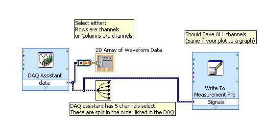
I did separate VI for reading signals from several channels on a map of NI USB-6251. I would like to combine these in a VI VI alone so that they can run that at the same time, however, there is an error if there is more that a single DAQ Assistant in the same--> error-50103 VI was held at DAQmx controls Task.vi:32 (the specified resource is reserved. The operation could not be performed as indicated.)
All the inputs of channel must then be read in with a single DAQ Assistant, but all of the data on different channels are not separated. Can save this data in a matrix or otherwise manageable which allow to facilitate the analysis of the data from the separate channel entries?
I tried to view the data in a file of measures, but then when I tried InPort data, I could all the data I wanted.
Hi AggieGirl,
Good afternoon and I hope that your well today.
First of all, you will not be able to have more than one DAQ Assistant by input analog or analog output task because the device has only one of each. So, you must have a DAQ task to HAVE and AO. (This is not the case for DIO static).
There is far from split signals using the express VI - signal splitter.
When you say you saved this file and it does not work, how it did not work? The Express VI - save a file of measures needed to manage multiple waveforms. Can send you your code & explain more about what was not OK on the file?
Thank you
-
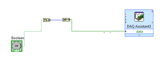
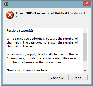
Control relay with Boolean switch using DAQ assistant 9481 - problems
Sorry for what may be a stupid question but I'm stuck in quicksand.
I use a relay module 9481 and have two external relays connected lines 0 and 1.
When I create a digital output 0 line by line, I can run the test inside the express and activate the relay and turn off without problem.
The generated block DAQ expressed expects a Boolean input of 1 d. (See attached photo).
I want to connect a Boolean switch relay line disk 0. You can connect live not because the switch is Boolean and the input is Boolean 1 d - I'm a conversation in the pict.
All plumbing lines display results, the relay never active.
Any bunch would be greatly appreciated! Thank you
Mr._Mechanical,
Welcome to the Forums of switch OR this forum is generally intended for products OR-SWITCH [such as the NI PXI-25xx & NI SCXI-11xx], I think I know the answer to your question.
I think the reason why it's a failure is the conversion you make generates a table of 16 Boolean [as the 'boolean to (0,1)' function creates a data I16 type] with your data more false data points 15.
When you try to control the relay, he sees 16 datapoints are you Commander to a single port [channel] and so error out.
My suggestion would be to use normal DAQmx digital output screw [with, he set up as ' Digital > single channel > single sample > Boolean (1 line) "] rather than the DAQ assistant.
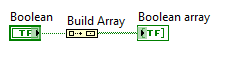
If you use the daq assistant, simply by using the function 'Building the table' will transform your simple Boolean data point in a Boolean array containing a single element.
While the DAQ assistant is very easy to use, I recommend that you use the DAQ assistant, because this reduces the features and increases the execution time.
-
DAQ Assistant does not export the values on the scale
Hello all-
Potentially stupid question but here goes: I'm using the DAQ Assistant to read in 4 analog input voltages, continuous sampling acquires data at 10 Hz 1 point, using LabView 12 on a machine with an acquisition of data USB-6341 simulated device (because my office is more comfortable than the lab!). I want to change the first two signals of voltage to temperature and humidity, respectively. I used the «create a new...» "in the 'Custom Scaling' drop-down in the"Voltage configuration"tab for each of these channels, named gave the slope and the intercept at the origin for the respective linear scales and click OK."
When I test the code - and yet once again, I'm not on a machine with a 'real' DAQ system, I use a simulated device, and it seems that NEITHER MAX generates a sine wave of long period with little noise on top for this - I do not get the results on the scale of my 'signal', I get the raw tension. (If you run my code, I will join, the Relative humidity must be between 0 and 100 and temperature-40 to 60, is not 0 to 5, for example.)
So, what happens? Is there some flag or setting that I missed? The scaling only works on voltage data 'real' of a 'real' instrument DAQ, instead of a simulation (which is why I mentioned twice!)? I have to do something in NI MAX as well as Labview?
Thanks for any help you can give.
John Easton
Simulations devices will not respond to custom scale. They are just supposed to allow you to configure your device without errors when you do not have the unit on-site.
"NOR-DAQmx simulated devices create a noisy sine wave to all the entered analog." Simulated data other set-up is not available at this time. »
http://www.NI.com/white-paper/3698/en
They generate a sine with an amplitude equal to half of your specified input range. If you want to work with simulated data that would be more realistic for your application, you could write a VI to generate the data and have a business structure to manage both "simulations" and "real", then you could switch back depending on whether you have access to the material.
I just checked this with a PCI-6254 I install and simulated a PCI-6254.
-
How can I programmatically change the parameters of voltage range in a DAQ Assistant
Hello
First post here.
I need to be able to change the properties of voltage range of a daqmx assistant DAQ based on user input. My material, an SCXI module - 1102C does not change this property on a running task, so I would together the range of input voltage analog before activating the DAQ Assistant, or break the DAQ Assistant immediately after it starts, set the values, and then resume.
I don't know how to change the task ahead because the DAQ assistant creates the task when it is running, and there is no job before that.
In the attached photo, I have a conditional section, configured to run only if the loop iteration is 0. I take the task of the Daq assistant, sending him stop vi of task, set the property and then send the task with the snap the vi task. I can watch him run with lightweight debugging on, and everything seems to work properly, but on the second (and all others) iteration of the loop, I read I. Max and it seems that a re DAQ Assistant set it to the 5V. You can see what's going wrong here?
BTW, there is a continuous acquisition and the code doesn't produce error messages when executing.
I've encountered a similar question someone posted here in 2006, but his question was specifically a Labview API (VB, I think) and not a real solution of G.
Attached are the real vi in question and a PNG of the block diagram.
Thank you!
Ruby K
First of all, if you want to start getting beyond the basics with the DAQ hardware, you have to stop using the DAQ assistant and do it with lower level VI DAQmx. There are hundreds of examples in the finder of the example. You can even make a right-click on the DAQ assistant and select open front panel. This will create a Subvi, you can open and see what is happening behind the scenes. Do it. I think you will find that the task DAQ is recreated on each (although I'm not 100 percent the way parameters are established or maintained in each section of this sub - VI).
The second problem is that you have a bit of a race on iteration 0 condition. These two property DAQ nodes are running at the same time. Thus, when you read the AI. Max, this can happen before or after the AI. Max is located in the structure of your business.
Thirdly, make sure that involve you your son of the error.

Maybe you are looking for
-
X 240 and 850 EVO 500 GB Samsung SSD
Someone has had the experience of installing the Samsung 850 series 500GB variety particulaly successfully in a 240 X? I cloned the disk of 120 GB original and installed in no problem, but his does not start with a Boot Manager error. I know it origi
-
The turn of my computer in the start menu has changed to Shut Down
Can someone tell me how I can get check it off my computer back in the start menu? I now have what looks like the old classic style of 'Shut Down' with the screen following with a "Shut down Windows" dialog box. Shut Down using works well but I prefe
-
Problem printing HP Photosmart series 4100 with black ink cartridge
Although the two black ink cartridges indicate that they r at least 1/2 they full r impression as if they were empty. Pale color impossible to read. What is the problem?
-
HP ENVY 15-ae109na: lack of drivers
Hi, I got my HP ENVY 15-ae109na for Windows 7 Proffessional 64-bit on your support page I can't find drivers for Wifi PCI Simple Communications Controller, USB controller and 2 of unknown devices. Please help, thanks
-
Smartphones BB Storm blackBerry sim card rejected
Someone had problems with the rejected SIM error? Sometimes my phone has this error at the top of the screen, I know it's not really important if you are traveling abroad. When I turned my phone off and back on the phone wants me to configure the sim