increase in the frequency of car to simulate signal vi
Hello world. I'm pretty new to labview. I want to increase the frequency to a vi simulation using the matrix of numbers of signals. the loop must browse the table and a frequency that will serve him entry to the simulation of output signal vi every 5 s change the frequency of 10 Hz to 20 Hz to 30 Hz and so on until the end of 1 kHz.
attached is a vi that I wrote, but something doesn't seem to not be accurate
Hi marco,.
in general, this question boils down to: think the stream!
What is the purpose of this inner loop FOR?
Why not use one loop at all?
Maybe like this:
Tags: NI Software
Similar Questions
-
I want to maintain the "frequency of sampling to report signal frequency" a constant.
I want to generate sine waves of varying frequencies, say, from 1 Hz to 1 kHz. Sometimes, a swept frequency sine wave. The problem is that I want to maintain the "frequency of sampling to report signal frequency" a constant. That means, the sampling frequency must be 20 or 30 times the frequency of the signal. This should be done automatically. For example, a sweep of 1-10 Hz, if the sampling frequency is 30 Hz at the beginning, it should be automatically updated at 300 Hz as the frequency of the signal reaches 100 Hz. Someone you will suggest a possible solution?
The basic generating function function has an entry titled "sampling info". It is a cluster and one of the elements is the number of samples. You just need to set this based on your frequency.

I suggest strongly that follow you the course 101 of LabVIEW.
-
Simple question about an increase in the frequency
I do a simple bode plot that will be used by a class of electronics. All I need to know is how to have a frequency input I can change after a delay loop. I would like to change the frequency of 100 Hz by loop.

-
Enter the number of samples to simulate signal vi on front panel
Hello
I need to change the number of samples in the simulation of signals vi without manually going through properties. Is there a way to change this pattern-block or front panel?
Thanks in advance,
Ragmo
Yes. You can convert the Express VI to a normal VI by right clicking on it and selecting Open the front panel and then you can change this vI and change the # of samples of a control constant. You can also use the functions non - Express VI as a base generating function.
-
Timed increase in frequency to "simulate signal.vi.
Hi all, I am a beginner of absoulte with labview so any help would be greatly appreciated, I want to increase the frequency of a sine wave generated, created using signal.vi simulation, increments together over time.
In other words, I want the signal.vi to simulate to produce a sinusoidal signal who will say during a period of time increase of 39.5 kHz frequency to 41.5 kHz increments of 0.1 hz.Thanks in advance for any help.
Here's a way to do a basic scan.

-
I have a vi that:
-Locate the USB port that RS485 communication device is connected
-sends a command to each sensor
-reads a response from each sensor
-performs a calculation on the answer
-saves the response to a file of measure
I used a flat sequence to query each sensor. I am trying to find a way to modify this vi in order to increase the frequency of sampling on the sensors. Currently, it takes 2000ms for question 4 sensors and write tot the measures file. Anyone have any ideas on how to speed up by programming? I am concsidering on the purchase of a device USB DAQ (USB6000) and rewriting of the vi. I was wondering if there was some tweek I caould make on the vi.
Thank you!
I meant put the time-out on the line, then the reading will be either timeout after 200ms or read the 2 bytes. Whichever is faster. Then deletes this 200ms waiting you. I have attached your vi to show you what I wanted. I did not notice that it is a hardware or wither then you might want to look in the data acquisition functions. It will clean up your code and are very easy to use.
-
I want to increase the frequency with which my laptop clock is set automatically by contacting an internet time server. In XP, there is a registry setting for the number of seconds between contacts with a time server. Where is this setting in Vista Home Premium 64-bit?
Hello
I'm in Seattle and generally use time of Microsoft servers
This is a list of time - stratum servers 1 and 2 levels.
A list of time servers Simple Network Time Protocol (SNTP) that are available on the Internet
http://support.Microsoft.com/kb/262680World time server
http://www.WorldTimeServer.com/World time server - Seattle (online)
http://www.WorldTimeServer.com/current_time_in_US-WA.aspx?city=SeattleThe State of Washington
http://www.WorldTimeServer.com/current_time_in_US-WA.aspxThe naval Observatory time
http://www.usno.Navy.mil/USNO/timeThis list, the phone number for time to Naval Observatory, CO - + 1 719 567-6742 (Colorado Springs)
and there is more information and links.
http://Wapedia.mobi/en/United_States_Naval_ObservatorySorry, no info on the atomic clock at the phone number. Maybe try your favorite search engine.
I hope this helps.
Rob Brown - MS MVP - Windows Desktop Experience: Bike - Mark Twain said it right.
-
increase the frequency of images in a flash animation
Somehow I can adjust the cadence of a movieclip without affecting the frequency of images that I put for the rest of the document.
I want to speed up this clip animation, and it would be difficult to adjust the calendar of this clip to achieve this.
Thank you
An example. I have a clip called
movieclipon stage. Thismovieclipa stop() in frame 1. Below will playmovieclipin double the speed of the stage frameRate and it runs in a loop.import flash.events.Event; addEventListener(Event.ENTER_FRAME, enterFrame); function enterFrame(e:Event):void { var targetFrame:uint = movieclip.currentFrame + 2; if(targetFrame > movieclip.totalFrames) targetFrame = 0; movieclip.gotoAndStop(targetFrame); } -
CPU runs at half the frequency in Satellite
Not sure if it is a problem, but the CPU runs at half the frequency. I put the high performance plan and still the same. I think it should work at full power.
I also tried to disable the CPU power option in the BIOS and nothing helped.
To monitor the use CPU - Z and Speccy.What you think about this?
Is it normal?Hello
The Intel CPU supports the Intel Turbo Boost technology
Dynamically, this Intel Turbo Boost technology increases the frequency of the processor as needed by taking advantage of thermal and power margin to give a burst of speed when you need it and increase energy efficiency when you don t.The CPU also supports Enhanced Intel SpeedStep technology
Enhanced Intel SpeedStep technology is a means of which allows high performance while meeting the needs of conservation of energy of advanced mobile systems. Conventional Intel SpeedStep® Technology puts both voltage and frequency in tandem between high and low levels in response to the processor load. Enhanced Intel SpeedStep® technology is based on this architecture using design strategies such as the separation between the voltage and the frequency changes and clock partitioning and recovery.
-
Satellite L30-134: is it possible to determine the frequency of 533 MHz RAM?
Hello!
I have Satellite L30-134 and used a module of 1 GB / 667 MHz (sic!) for a while. Same Toshiba says maximum speed 533 MHz memory he recognizes module PC-5300 and sets exactly to 667 MHz.
I decided to increase the RAM and bought another PC-5300 1 GB stick.
... RAM is only 1 GB with two modules together. The two sticks are OK - L30 sees 1 GB and works well with each of them separately.I know that the reason is that Toshiba couldn't work with greater speed on the two banks (or something like that).
So. It seems to be a good idea to set the frequency of 533 MHz and it should work.
The only question is to know how to do it? BIOS Setup is almost empty and does not have these settings.One advise, please (except to buy sticks more :)
Hello
Laptop Satellite L30-134 is a processor 1.5 GHz of Intel-Celeron-M (Yonah).
Is this good?This processor supports a 533 Mhz bus and if you use modules of 533 Mhz RAM then will automatically solve this value!
Simply put, you do not need to change anything manually! Everything is controlled automatically.Concerning
-
VI to convert input signals NI 9402 in a RPM value, based on the frequency of the pulses
Hello
I'm looking for a VI convert an input signal NI 9402 in a RPM value, based on the frequency of the pulses. Is there such a thing that exists in the library of national instruments?
I run LAbview 2014 integrated control and monitoring on on a cRIO 9802 high performance integrated system with NEITHER 9402, 4 channels, 50 LV, LV TTL Module input/output digital, ultra high speed digital i/o for the cRIO module.
Any help would be greatly appreciated.
The easiest way is to use the FPGA to get the time between the edges of your pulse increase (shift registers to maintain the current situation and the time will be necessary). This will give you the period. If it's a single pulse per turn, then the number of laps is just 60/T, where T is the time in seconds.
-
Change the frequency AO AO DC voltage scanning scan?
Hi all
I am very new to labview, but find the forums and examples extremely helpful. I probably spend 50 + hours to familiarize myself with tutorials and general information, but I am at a point where I need your help.
I'm unable to change the example "AO frequency sweep" found here (see custom_sweep_1.VI) to allow me to sweep the voltage. My instinct is that I don't need of the ' waveform buffer generation VI ' and that I should be able to remove the associated entries since I'm only interested in a sweep of DC voltage. It is also called create_log_frequencies.VI, and I'm fairly certain that I can use it as written and simply change "frequency", "tension". My work of the custom_sweep_1 changes are attached as custom_sweep_Voltage.
The problems I am having with the edition of custom_sweep_1 are:
(1) I don't think I understand very well how or if the parameters associated with waveform buffer generation VI relate to a sweep of DC voltage.
(2) an extension of 1): the loop depends on the samples and Cycles by buffer and I don't know how / whether to replace these values
(3) the .VI DAQmx Timing (sample clock) receives its sampling frequency of output waveform buffer generation VI, but I think I can use 1/scan time to replace this (?)
(4) the DAQmx Write.VI gets waveform buffer generation data, but if I can get around this VI and AO tension of wire directly to write DAQmx then I think I can use minimum voltage as my entry of data (?)
(5) after the implementation of these changes, the custom_sweep_Voltage runs, but I get error 200609:
"The possible reasons:
Generation cannot be started because the size of the selected buffer is too small.
Increase the size of the buffer.
Choose the size of the buffer: 1
Minimum required buffer size: 2"Task name: _unnamedTask<3A>"
I also note that I tried other ways to create the sweep of voltage DC VI:
(1) I have tried change the tracer IV example (found here), but it's much more confused than change the frequency sweep.
( This tutorial and sample 2) block diagram looks like straighforward, and I also work on understanding what Assistants DAQ 1,2, 3.
Any return would be great. I think it is clear that at the very least, my poor understanding of 'buffer' is if the cause of my confusion about the change of frequency scan, please do not hesitate to share any information you have.
Thank you very much for the help,
-Esperanza
Additional information on my project/progress using labview follows below:
My final goal is to determine whether or not the resistivity of a sample of organic driver changes over time. For this I want to compose a VI simultaneously sweeping the output voltage DC-5 to 5V periodically during 24 hours and measure the voltage drops to my load resistance (to determine the current in the circuit) and the sample. I use a USB 6259 DAQmx and that you have correctly configured my circuit. I work two screws that I created with the DAQ assistant and by changing some of the examples, I found online. Output voltage (of an AO) but I have to manually select the voltage value. The second reads voltages in three samples of interest and writes the data to a PDM file. If you've read this extreme sensation and still make a contribution, my next goal after finding how to sweep the voltage is to combine this with my VI measure VI. I think it will be relatively simple, but still, I rejoice in all your comments!
I solved this problem. I have changed my approach to be similar to the last link in my post. AO frequency scan approach is much more complicated that I need. Thanks for the help.
-Esperanza
-
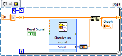
Purpose of the "Signal Reset" bulk "Simulate Signal"
Hello
What purpose of the "Signal Reset" in the block "Simulate Signal".
I searched, which once activated, it affects the default value, which is 0 in the output of the block "simulate Signal".
But it seems that the functionality of the 'reset' Signal is different.
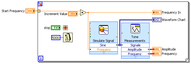
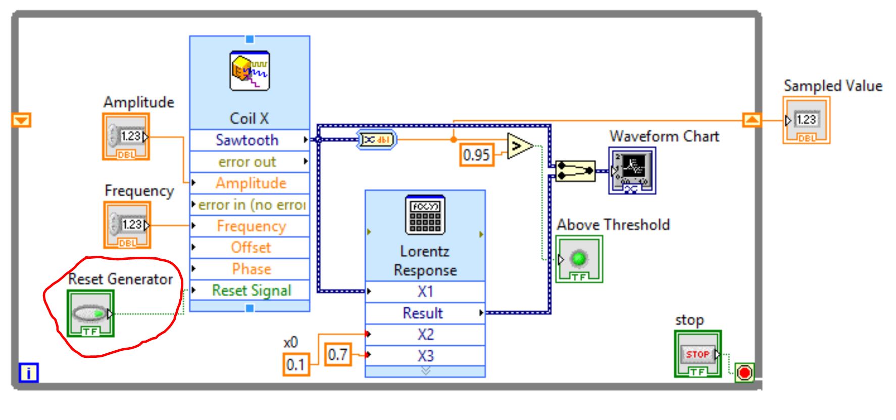
On figure 1 - Schematic of my installation with pushbutton "Reset Generator" below on the left.
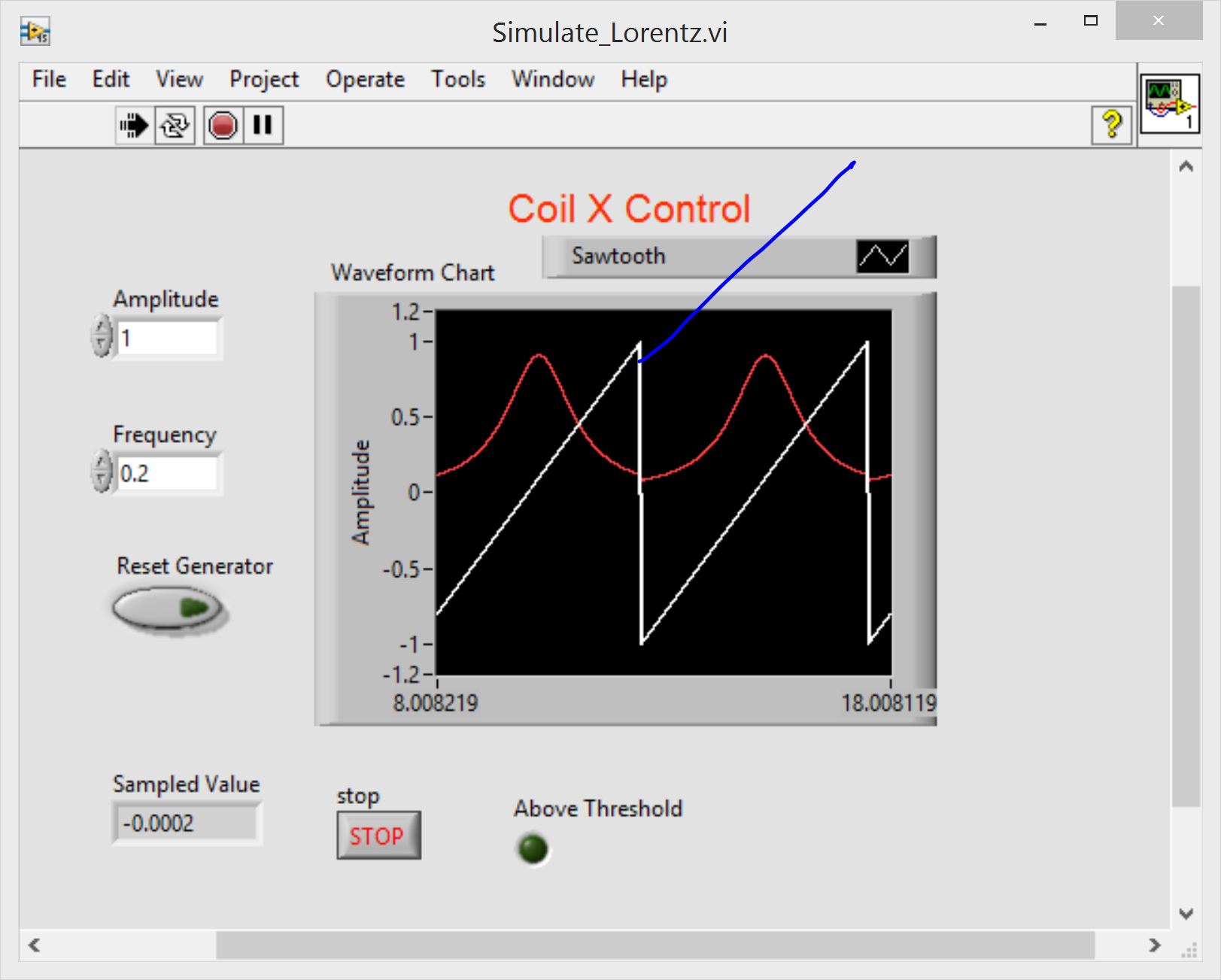
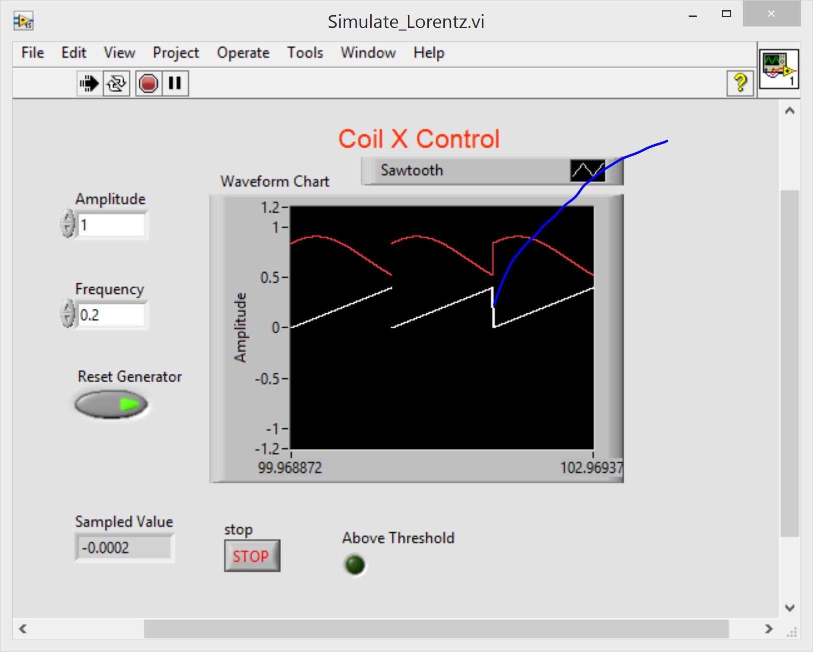
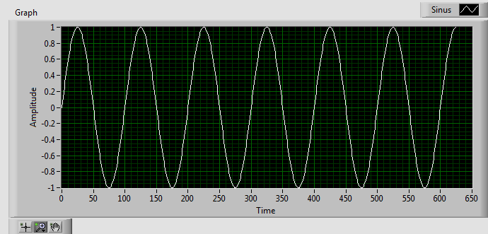
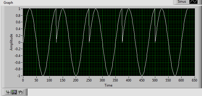
On Fig. 2 and Fig. 3 - the output of the 'Simulate Signal' block and some derivatives of signal with 'Reset Generator" OFF and WE accordingly.
As you indicate, in the case WE , the output is not 0.
Thanks in advance for the clarification
Pavel
Fig. 1
Fig. 2
Fig. 3
The reset is used to "reset" the phase of the signal to its default value when the value 'True '. If you leave the value of "reset" to "false" and you run the Simulator signal in a loop, you will get a contineous waveform, even when your signal Simulator does not generate a whole number of cycle (combination of signal frequency, sampling frequency and number of samples). If you set the "reset" to "true" the waveform will be interrupted (the stage will be set to its default value in each iteration).
Here is an example:
"RESET" = FALSE, see chart below:
'RESET' = TRUE, see the chart below:
-
How to measure the frequency of NOR-DAQmx RPM tasks
Hello
I'm trying to measure the frequency using the NI DAQmx task and then convert it to a RPM if possible.
I have the following material available to me.
I have a block SCXI-1327 terminal, as well as a 6289 PXI multifunction data acquisition Module SCXI 1126.
I wired in a mag ai7 sensor on my 1126 and then of the passage of an object metal I get a range of 6-8, so I am able to read the mag sensor.
What I'm trying to do is somehow convert this analog measurement a RPM using the NI DAQmx task only.
Any help would be appreciated.
Hi, smooth,
Yes, you would select linear, then put in the result of this calculation of the slope.
The Manual recommends a minimum frequency of at least 15 Hz for setting low range. This card is not really designed to measure the frequency for a single pulse over a long period of time.
The number of LAPS down (assuming one pulse per turn) that we recommend that you measure with the 1126 is so 900 RPM. If you need measure low revs, and you cannot increase the number of impulses per turn, you could consider either read the signal as an analog waveform, or if it's a digital pulse, using a counter to basic task. In this way, you can use any method you want to handle the situation where there is only a single pulse in a long time.
-
Questions about the frequency step response
Hello
I use the Signal Express 3.0. I'm not clear on the transfer functions in step of frequency response with different modes of calculation of the average. What I got from the help file is this H (f) = Sab (f) /Saa (f) which is cross the frequencies on the spectrum auto where is the pulse and b the signal response signal. When the mean quadratic value is used, I wonder if the transfer function becomes greatness of cross spectrum divided by the magnitude of the spectrum of the car. When an average of vector is, everthing is used in complex numbers. He averaged temporal signals, frequency domain signals, or the results of transfer functions?
Thank you very much.
The algorithm to calculate the spectrum is the same in both modes. However, the method of calculation of the average can have a huge impact on the outcome. Mean quadratic value is performed on the spectrum itself, after the calculation. Vector averaging is done on the input signals before the calculation. With an average of vector signals must be consistent (have the same phase) or the result will be bad due to the signal being on average by far.
Maybe you are looking for
-
Install Windows 98 SE on Toshiba Portege 300ct
Greetings,Im stuck on this one, I got a Portege 300ct a friend that I use for two-way radios program. It is running Windows 98 Second edition with problems. This computer has no FDD but I have the docking station with CD player. I reformatted the dri
-
76376084System disabled
-
I can't play my Apple music albums downloaded?
A few days ago, I decided to sign up for the Apple Music 3 month free trial. Then, I went and downloaded about 4 albums, so that I wouldn't have to have the Internet connection to be able to listen to them. However, the next night, when I tried to
-
IdeaPad Y560 dvd drive ide or sata?
Is Y560 dvd drive ide or sata? I want to replace it with a hard drive so I need an IDE HDD is ide?
-
Hot Keyes for the brightness of the monitor on the SL510
I have a very annoying problem with hotkeyes to adjust the brightness of the screen! After the latest version of the driver hotkeyes they do not work. I can not increase or decrease the brightness. Pressing down and can not change anything. And there