Layer of Business Model and mapping
I am trying to create a logical dimension table by dragging the corresponding table of the physical layer. However, in the layer of business model it appears with a yellow icon indicating that it is a logical fact table. Please help me how to create a logical dimension table in the layer of business model. Don't know what I'm doing wrong here.Thank you.
Blanchette,
Make a right-click on the field---> properties--> Tables-->. Upwards and downwards and align the way you want
Thank you
Saichand.v
Tags: Business Intelligence
Similar Questions
-
Rename the business model and business sector
Hi friends,
I want to change the name of my business model and also the area in question.
If I rename in RPD's business model and so as my presentation files it will be affact my reports already made?
If so, how to solve this problem.
Help appreciated.It's expected OBIEE behavior, Alias only supports existing reports, running, but when you want to edit reports, you must use the Advanced tab, change. Then only the columns/tables available on the left side.
-Madan
-
How to set a path of exploration in the business model and the mapping layer
Hello
My table contains a hierarchy vertical, as shown below
ID names Parent_Id
--- --------- ---------
1 India - 1
Gujarat 2 1
Ahmedabad 3 2
USA 4-1
5 Texas 4
Dallas 5 6
California 7 4
Los Angeles 7 8
In top structure
USA has no parent so his Parent_Id is - 1.
In Texas and California is a State of the USA so its Parent_Id is 4.
Dallas is a city in Texas, its Parent is 5 and Los Angeles is the city of California so his Parent_Id is 7.
My path of drilling must be USA-> Texas-> Dallas
-> California-> Los Angeles.
How can I do this without changing the structure of the table.Hello
You can create a view in the physical layer and can create different columns, corresponding to the country, State and city, and can use them in a hierarchy. You can create the query in the following way
Select b.SID as Country, b.name as state, c.name as city, c.id of
(select name, id and parent_id where parent_id =-1 dummy).
(select name, model id and parent_id) b.
(select name, model id and parent_id) c
where a.id = b.parent_id
and c.PARENT_ID = b.idYou can use C.id as a key to join with other tables. After that, you can migrate this table to MDB and create a hierarchy on this basis.
Hope this helps
Thank you
Sandeep -
Table repository - Business model - 10g OBIEE logical to physical table, column mapping is empty
Hi, I'm really new to OBIEE 10 g.
I've already implemented a database SQL Server 2005 in physics and import a vw_Dim_retail_branch view.
The view has 3 columns: branch_id, branch_code, branch_desc.
Now, I want to set up the business model to map this physical table (view).
I created a new business model
Adding new logic table Dim_retail_branch
In sources, added the vw_Dim_retail_branch as a table source.
But in the logical table source column mapping tab window, it is empty. I thought he should be able to identify all of the columns in vw_Dim_retail_branch, but no. The spectacle of the mapped column is checked.
What should I do here? Each column type manually?
Hello
You can drag and drop the columns from the physical layer to layer MDB.
Select 3 columns and drag and drop it to the logical column created in the MDB layer.
For more reference: http://mkashu.blogspot.com
Kind regards
VG
-
How to limit the developers of the RPD to some business models?
Hello
I would order that can change business RPD models.
I have thought to create application policies RPD_developer, create rpd_developer roles (one for each business model) and filter their access rights.
No idea if this is possible?
Thanks for your help
concerning
Andy
Not at the moment a binary RPD. The 'Permission' concern mark resp. restrictions. the read/write access on the presentation as well as the physical layer layer - but those who are related to the analytical use through answers / SmartView etc. and RPD will not work.
In theory, you could do it in an RPD which is divided into pieces MDS XML and then assign subsets some developers. I say in theory because you would have to if ensure no reusable entity and object exist always... which basically will never be the case unless you are ok with the duplication of objects to get around this fact.
-
Adobe Stock Photos for my business models
Hello
I'm a Web Designer & developer, I want to know can I use the adobe stock photos on my business models and sell them, in fact I want 1 or 2 photos for each cursor model or background, I want to say just 1 or 2 photos for model and no more
Thank you
Given that these are images on business models and used for sale, Extended is the solution for you.
You can navigate through shared links in above posts.
-
How to add an array of stand-alone physical layer to the Business Model
Hello
I have tables from 2 different database sources in my physical layer.
My business model is currently using only the tables of a database. My second database in the physical layer, I don't need a single table and who will be an array of stand alone, to my presentation layer.
1. must you go through my business layer or can it be added directly to the presentation layer. What are the steps?
2. can I restrict permissions on this table stand alone to the administrator?
Thank you.(1) create a view with a single column using sql (select 1 of the double) in the physical layer and attach it to the table using a complex join in the physical layer (1 = 1).
A movement that set the column as a key in the physical layer and mdb to MDB.(2) you can restrict access to the presentation layer of table
Double-click the table of presentation-> Permission-> here layer, you can restrict access by user or groupThank you
Vino -
create a business model when there is only a single source table
Hello
How to create a business model when there is only a single source table in the physical layer
Concerning
SwathiIt is very well possible and feasible. His name as a single Table model. Good example is HIS domain system where we have just one physical source. No need to create aliases in physics. Just use the same table twice in the MDB with a single logical table as a model made... As for example the number of users (aggregated). Then apply normal complex participate MDB and present in the presentation layer.
http://gerardnico.com/wiki/dat/OBIEE/single_table_model
http://gerardnico.com/wiki/dat/OBIEE/sasystem -
OBIEE 10G - repository Business Model adding fact Table
Hello
I tried to search the forum for problems similar to this one, but did not find any thread that responded to my doubts.
I'll try to explain this very well (without images it's complicated). Suppose we have a schema with the following tables:
Dim_1, Dim_2, Dim_3, Dim_4, Dim_5, Fact_1, Fact_2
Fact_1 is connected to Dim_1, Dim_2 and Dim_3
Fact_2 is connected to Dim_2, Dim_3, Dim_4 and Dim_5
And on the business of the repository model, we already have a model with the following tables:
Dim_1, Dim_2, Dim_3 and Fact_1. It was the State of the repository, the last time that we have saved.
Now, I want to add to the activity model, the table Fact_2 and the Dims that connect with Fact_2. What should I do here?
If I drag the physical layer only the tables (Dim_4, Dim_5 and Fact_2 like Dim_1 and Dim_2 already exist in the business model) when I check on the business model of the table Fact_2 and direct joins diagram I see only joins Dim_4 and Dim_5 and not joined to the other two dimesion tables (Dim_1 and Dim_2). I don't know if OBIEE will always act as these joins are made or if I'm having problems when I'm working on presentation services.
If I drag the physical layer, the tables (Dim_2, Dim_3, Dim_4, Dim_5 and Fact_2) I'll see all the joins, but I'll have on repeated business model tables, something like this:
Dim_1, Dim_2, Dim_2, #1, Dim_3, Dim_3, #1, Dim_4, Dim_5, Fact_1 and Fact_2
So what is the solution here? I have to redo everything I want to add something, and this situation occurs? Isn't his smart and there must be a better solution. I know that I can start direct joins manually, but that is the best solution that I can find in this situation?
I hope that I was clear :)
Thank youHello
I have proposed this approach because your layer of MDB was already designed with fact1 joins. If you have already designed MDB, once you drag fact1, fact2 & Sun 1-5 (after physical joins) complex join will be automatically created in MDB. Now that you're at halfway, it is the only way to include the tables.
Rgds,
DpKa -
A way to transform a model chart/map in an editable model?
Hello!
I've been curious about this for a while now, so I was hoping that maybe some of you knowledgeable people here could shed some light on this for me.
I often use Adobe Illustrator to create graphs, maps and diagrams which contains texts for my employer. Basically, he tutors in development of the business at the highest level, and I give it with graphics, presentations, powerpoint, animations, and many other things for his seminars.
Now, sometimes we use our graphics and maps without content (ie. no text, arrows, etc.) so that it can let companies fill the values themselves during their exercises in the training course.
However, my (or should I say OUR) problem has always been to find a way for me to 1) template in Illustrator and 2) to convert the model in an editable chart, or map, complete with text, arrows, etc.
I just finished a little test, however, and it seems pretty good.
What I did to create the map in Illustrator template, save it as a PDF file, and then open the PDF file in Adobe Acrobat Pro and insert the form fields in the empty boxes (the boxes on the map must be empty, since companies must fill these boxes with values that correspond to their own (read agenda ((: business)).
After filling the boxes with form fields, I recorded and re-opened to try to enter some text by default, and it seems to work pretty well.
What I wonder, however, is whether there is a far more effective way to create a template chart chart/map which can be modified by others, easily and effectively.
Maybe someone here knows of a viable solution?
See you soon,.
ufoldager
How your end users (the public) and your boss (the presenter) should be able to change patterns?
If the presenter and the public edit the labels of text, but no color, position or the size of the objects, then a PDF form will work. Models for each provision of static graph diagram of construction will be more painful in Illustrator than necessary, due to the lack of the illustrator of diagramming tools. But if you need to build models in Illustrator, you could make a template file "drag & diagram construction kit drop" by taking advantage of these features and practices:
- Modularize the schema of the page by creating all objects in order to comply with the grid increments.
- Store each object (and groups of reused objects) as symbols. For example, you may want a symbol which consists of one of the ellipses and his arrow curved to the left. an another that consists of the ellipse and its spire curve to the right, the other with the arrows or the loop arrow, etc etc.
Now you can build quite quickly a new arrangement of diagram of objects by dragging and dropping them on the page of the symbols palette and their position on the grid alignment.
Then save a copy in PDF, open the PDF file in Acrobat Pro, add the fields and activate the form.
For example, I use the method described above for a set of "ladder logic" electronic cards that describe the programming of an automotive module logic. A complete set of logic cards may be about 80 drawings. But because all the graphic elements are modularized to an alignment on the grid, I can build a new set of blank schemes within a reasonable time and replace PDF files resulting to technicians who then type symbol labels in prepositionnes PDF form fields. But then again, this implies that the graphics in the diagram are made by you, prior to use in front of the Group and the graphic elements of diagrams are not manipulated to the seminar by the presenter or the audience. that the text labels are manipulated.
IE7
-
How to interface a simple way using LabVIEW 2009 simulink model and SIT?
Hello
I finally found a way to use a template simulink with LabVIEW and the Toolbox to SIT, but I'm not satisfied.
If you have any suggestions, the link of resource that I missed, please do not hesitate to answer
Note that I do not know much about simulink, so that is my question seems stupid, let me know what

Software configuration
OS: Windows (not an RT target)
LabVIEW 2009
SIT 2009
question 1: interfacing the model DLL (mapping considerations) with a driver VI
We have created a model of DLL by using the 'Workshop in real time' tab in simulink.
In LabVIEW, launch us the tool 'SIT connection manager' and try to use the DLL with a driver VI by mapping the e/s model for screw/lights orders.
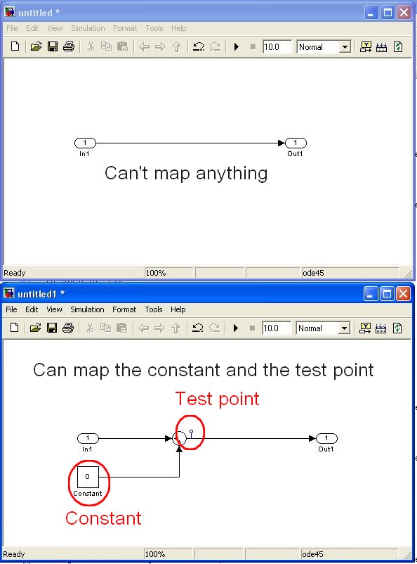
The fact is that I fail to connect to my controls/indicators VI/o model because they do not appear in the mapping dialog box.
The simulink single objects that I managed to map are "constant" and "test points" while I need to edit the template simulink itself (example below)
Are in e/s model, not considered as part of the parameters of the model? (this could make sense because the mapping says in fact that it operates on "model parameters")
Is it possible to link the IO model VI commands/lights?
Note:
-the "configure HW i/o mapping" dialog box allows me to map model e/s with e/s HW...
-The examples also use these "constant" and "test points".
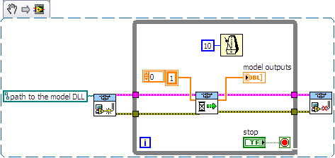
2nd question: use of direct screw SIT
I tried to use the DLL directly with the screws SIT (code example below)
This kind of code works well on another project (target of 8.0/RT LV) but not on the current project (LV 2009/Windows)
The second stage of the model never ends:
-0-index of the loop works as expected (model doing its job).
-index of the loop 1 starts normally, but execution is stuck in the 'SIT scheduler.vi.
Then I have no choice that to kill LabVIEW ("Reset screws" windows appear if I try to stop/close them).
Is there a reason that I do not see what explains this behavior?
Thanks for reading.
Any help appreciated.
Kind regards
Hello
I spent some time analyzing the VI driver as you suggested.
Here are my findings.
Question 1: the SIT connection manager does not pass to the model SW controls/indicators. Only, it allows the user map HW AIs/AOs.
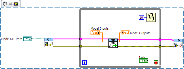
The only solution I found (to have a SW - for example a shared variable - object that is mapped to an input/output model) is to customize the VI driver that is scripted by the SIT Connection Manager ("_Base
rate Loop.vi" in the flat sequence structure named "read code") Question 2: after spending some time in the VI driver, it seems that the VI to call right is not 'SIT scheduler.vi' but 'If SIT take model no time' (which uses the other as a Subvi)
My conclusions are correct? If I use the API in the wrong way, please let me know.
Kind regards
-
I am familiar with older versions of Photoshop and wanted to download a version for my Mac make flyers and maps visit/menus for my coffee. I use a lot of pictures, but I think it's the wrong program as he looks nothing like anything I've worked with before. OOPS! Did I miss something or should I try to refund and buying back shares?
And what exactly do I get if so? I'm not super skilled so a basic program is good for me!
Thank you! ~ K
Hi kelstardragon,
If you purchased Lightroom, then this application is not good for the creation of Flyers or business cards.
I suggest you take a refund and buy Photoshop, as it is the best application according to your needs.
Kind regards
Tanuj
-
creation of model and choosing the resolution of the model
In creating models, if I paint the model first with the Brush tool, a model of texture I create, then save, edit > set the pattern, done the resolution of the document determine the resolution of the model is saved?
I am wanting to make sure that when I go to print my images that resolution templates I create and apply in the work are high enough resolution so that when I use the function of "scale" inside layer styles everything by manipulating the size of my boss, even if I step up the boss, it will contain always high enough details to avoid pixelization when printing...
I guess right now all I can do is to create models with the best resolution I want my output as? (But this would probably increase the loading time of my dialog box templates, if I have a lot of model texture to salvation ground?) ...
Is scaling a trend upwards or downwards in the layer styles resample? He throw or average in pixels and blur the boss?
At the beginning I was looking for a model palette where I could choose a pattern and paint with a Brush tool... but I overcame this by creating a new layer, apply the model as a layer style and paint layer with the Brush tool... the advantage is scalability and its editability
Was looking for a folder option in the layer styles dialog to consolidate my styles, in the region of swatch... but once again I guess I can create these files myself in the folder "load styles...". ». 2 steps than another.
Photoshop works with pixels, not with the PPP when you set templates define you a number of pixels as a rehearsal room. PPI resolution has nothing to do with this and is necessary only when you print.
-
How two business models can be connected?
Hi all
Can we connect 2 business models in MDB layer logically?
Thank youHello.
It is not possible to connect different BM 2 in the layer of MDB. What you can try to do - create new BM containing objects of these 2 BMs.
-
Hello
I'm doing the $ 1, $ 2, sum3 and suma total sum 1 + sum 2 + sum3. For example, I have six elements. Articles 1 and 4 make sum 1, points 2 and 5 to the sum of 2 and so on. Finally, all money is total. Is it possible to make in the business model?
Thanks in advance.Hello
I think that you can do using a filter like this object
FILTER (measure.column USING dim.column IN ('RC', 'Kasko'))
In this way, you can build your different totals.
And you can create a total with different objects.
I hope this can help you.
KR,
A
Maybe you are looking for
-
Will my iphone 6 bought a piece of apple in New Zealand store? I have a contract with Verizon.
I received different answers to this question. Some say that I'll be able to use it as long as I haven't bought the phone from Verizon.
-
My new HP Officejet Pro 8600 will not scan more than 300 DPI when scanning individual photos on the glass plate. I do not use the document feeder. I use this printer wireless on an iMac and a PC.
-
Desktop Security 2010 Malware virus
How do you get the path of Desktop Security 2010 Malware virus from my PC running Windows XP. I also have Norton Internet security 2010 and Spybot - Search & Destroy - and the virus got through all this! Thanks in advance for your help
-
Linksys E4200 - Skype internet killing
Hello Recently, I went from a router D-Link GamerLounge for a new Linksys E4200 using the default firmware, upgraded to the latest version. The router seems to work fine - except when someone uses Skype, and performance of the network decreases drast
-
Printer HP Photosmart C6380 replacement cartridge
Need a replacement for a with number CB321WN Option 140 HP 564XL black. I learned online HP chat that this cartridge is no longer available. A black product 564XL number 140 Option CN684WN of the order said. I did it (ordered four) and when they ar