Masking of legend in the chart
I'm hiding the lineSeries serial line
lineSeries.visible = false;
but his legend is shown on the chart.
How to hide the legend for the hidden lines series entry?
Hello Asif,
You must write an ActionScript to achieve this functionality... Its not as simple as it all as you make visible lineseries = false... the legend item will go
Suite... You must explicitly delete and add series... as shown in the code below:
Import mx.collections.ArrayCollection; [Bindable]
private var expensesAC:ArrayCollection = new ArrayCollection ([] collection
{Month: "Jan", profit: 2000, expenses: 1500, amount: 450},
{Month: benefit "Feb": 1000, expenses: 200, amount: 600},
{Month: "Mar", profit: 1500, expenses: 500, amount: 300},
{Month: "ARP", profit: 1800, expenses: 1200, amount: 900},
([{Month: "May", profit: 2400, expenses: 575, quantity: 500}]) ;
private void addLineSeriesToChart(item:String):void
{
var isFound:Boolean = false;
for (var i: int = 0; i< linechart.series.length;="" i++="">
{
If (lineChart.series [i] .yField is point)
{
isFound = true;
}
}
if(!isFound)
{
var newLS:LineSeries = new LineSeries();
newLS.yField = item;
newLS.displayName = item;
var tmp:Array = lineChart.series;
tmp.push (newLS);
lineChart.series = tmp;
lineChart.invalidateSeriesStyles ();
}
}
private void removeLineSeriesFromChart(item:String):void
{
var objToRemoveIndex:int;
var isFound:Boolean = false;
for (var i: int = 0; i< linechart.series.length;="" i++="">
{
If (lineChart.series [i] .yField is point)
{
objToRemoveIndex = i;
isFound = true;
}
}
If (isFound)
{
var tmp:Array = lineChart.series;
tmp.splice(objToRemoveIndex,1);
lineChart.series = tmp;
lineChart.invalidateSeriesStyles ();
}
}
private function addProfitLineSeries (): void
{
addLineSeriesToChart ("Profit");
}
private function removeProfitLineSeries (): void
{
removeLineSeriesFromChart ("Profit");
}
]]>
Height = "100%" width = "100%" layout = "horizontal" >
paddingLeft = "5" = "5" paddingRight
showDataTips = "true" dataProvider = "{expensesAC}" >
If this post answers your question or assistance, please mark it as such.
Thank you
Jean Claude Chari
Tags: Flex
Similar Questions
-
How to change the value of the legend in the chart OBIEE
I have 2 columns A and B are measure columns.
How can I change 'A' and 'B' in the legend of my bar chart 'LIA' and 'ACTIVE', without changing the A, B the name in my area.
Thanks for any help!
Published by: user6388889 on November 18, 2012 17:46
Published by: user6388889 on November 18, 2012 17:55Hello
by changing the criteria---> report column (Custom headings: it's like alias column name) you can solve.
Thank you
Deva -
How to show the legend in the chart?
Is it possible to only show the graphic legend? I tried to look in the XML of the application, but I have not found anything. Help, please. :)Just add a custom chart
See also:
http://obiee101.blogspot.com/2008/08/OBIEE-date-time-scatter-graph.htmlconcerning
John
http://obiee101.blogspot.com
-
Hi all
I make a program to display the number N of parameters on a single graph.
I managed to do it on my test vi, but when I code the same coding for my true vi, the arrangement of the legend is not expected.
She always jump to the second parameter instead of the first.
However, when I check only one parameter, it displays on the legend.
On my test vi and also my real vi, the coding looks like the file below 1 (.jpg) - exactly the same thing.
2.jpg--> watch my front vi test.
3.jpg--> watch my true vi whose legend is not by expected.
I'm really confuse different results, even if it comes from the same code.
Please notify.
your help is much appreciated.
Thank you.
Kind regards
Roziela
DaveRoziela wrote:
Looking at the program, I only managed run my real.vi if I check the box in order without skipping any checkbox.
If I missed a single checkbox, this error message came up:
Oh sorry, Yes, we have to make a small change like this, of course:

(increments only in the case of true value. The other case is wired through).
-
How to set the visibility of names intrigued in the legend of a chart XY-automatically
I have a XY garph which shows 3 plots. Sometimes, I need to close a few plots on the chart. I can do it. But I also want to remove the name of the plot on the chart as legend, I couldn't do it. How can I do? The program is attached.
The solution is actually a little more complex that you can expect, as you need to change both the plot and the characteristics of the plot. Something that should work, even if it is not very optimized and has some momentary display problems, expected, is attached.
I didn't have LabVIEW 2009 on my development machine, so I've edited in LabVIEW 2011 and registered for a previous. I don't think I used something again, so it should work. Let me know if you need more information.
-
Area of the graph under the graph and not next to the chart legend
Hello
I need to display 1. Graph legend below the graph and not next to the chart area and also reduce the space between the caption box
2. the values in the chart are affiches.1745%, 4.596%... I need to round up these values.
My card code is:
chart:
< graph graphType = 'PIE' depthAngle = '50' depthRadius = '8' pieDepth = "30" pieTilt = "20" seriesEffect = "SE_AUTO_GRADIENT" >
< title text = "Answer category" visible = "true" horizontalAlignment = "CENTER" / >
(< LocalGridData colCount = rowCount="{count(.//G_DT_NON_NA_EQUITY1) '1'}" > "
< RowLabels >
< xsl: xmlns: xsl foreach = "http://www.w3.org/1999/XSL/Transform" select=".//G_DT_NON_NA_EQUITY1" >
< label >
< xsl: value-of select = "SPER_STATUS_TXT10" / >
< / label >
< / xsl: foreach >
< / RowLabels >
< DataValues >
< xsl: xmlns: xsl foreach = "http://www.w3.org/1999/XSL/Transform" select=".//G_DT_NON_NA_EQUITY1" >
< RowData >
< cell >
< xsl: value-of select = "CNT20" / >
< / cell >
< / RowData >
< / xsl: foreach >
< / DataValues >
< / LocalGridData >
< / chart >
I appreciate all the help
best regards and many thanks
Bhavana -
The chart legend: worked in beta, no longer works in Prod
Hello world
The legend attached to the LineChart poster is no longer the appropriate color. In other words, the line in the chart is red (as requested), but the 'legend' is black. It is supposed to be a red square and the word 'Jobs', but I get a black square (as it is not gathering because it should be red).
< s:SolidColorStroke id = "s3" color = "red" / >
...< mx:Legend dataProvider = "{myChart}" / >
....< mx:LineChart Id = "myChart"
x = "10" y = "40" width = "600" height = "400".
dataProvider = "{platformsData}".
showDataTips = "true" >
....
< mx:series >
< mx:LineSeries yField = 'id' = 'Jobs' lineStroke "{s3}" =displayName / >
< / mx:series >
< / mx:LineChart >
It worked on Beta, but is no longer works in Production. Is this a bug or I need to change the encoding to accommodate new modes of Production to deal with this?Kind regardsEGMTry using instead of mx.graphics.SolidColorStroke mx.graphics.Stroke.
You can get the warning of disapproval, but it renders the color legend properly in my case.
K
-
Change the "Default" location for the chart legend
Hello
By default, when you create a natalLa legend appears to the right of the chart itself. As a society, all our legends are upstairs. Is there anyway to set the default location of albums rather than right?
Thank youHi Baqpuss,
You should be able to edit the files cxml and pcxml that are used by Corda Popcharts to set the default value.
You will find the files that will be of interest to you:
C:\OracleBI\web\app\res\s_oracle10\popbin
C:\OracleBI\web\app\res\s_oracle10\chartsupport
C:\OracleBI\web\app\res\s_oracle10\chartsDon't forget to make a backup before you change them. Once you have completed your changes, you must restart the BI server and the presentation service.
For more information about editing the files, see the reference document. C:\OracleBI\corda50\docs\graph_reference\graph_reference.PDF
I recommend you to create a chart type custom rather than change the existing chart types.
John Minkjan has done a bit in this area. See his blog for more details: [http://obiee101.blogspot.com/search/label/CORDA]
-Joe
-
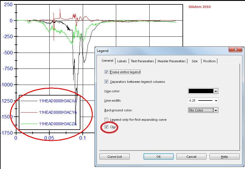
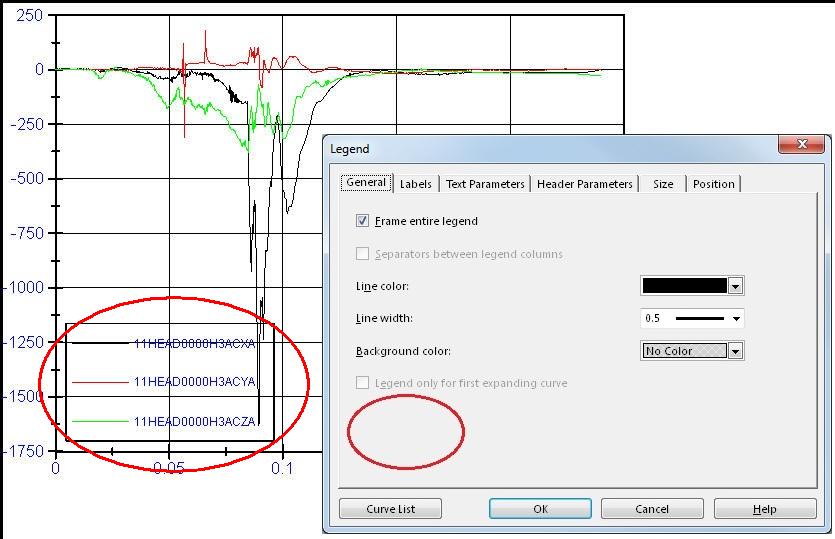
The cutting of a legend against the axes in tiara 2011/2012
Hello
until DIAdem 2010, it was possible to cut a legend in a report against the axes, but not against the chart.
To do this, I had to create the layout in the DIAdem 8.1 set the clipping and then convert TDR LPD.
As you can see below, the legend of tiara cache the grid axes and leaves the visible graph.The Tower using DIAdem 8.1 to create the page layout is no longer works in tiara 2011/2012
How can I display a legend in DIAdem 2011/2012 which mask the axes and leaves the visible graph?
Thank you
GEMÜ
You are right, 'Notes' of DIAdem 2011 you will find the following information:
DIAdem 2011 compatibility and DIAdem 2010
In the REPORT of DIAdem clipping settings "Only axes to hide" and "Hide axes and curves" is not available, even if you load a former route of the HPA. Instead, you can specify a background color for each object in the report. In the settings of object, select white as the background color if you want to display the report on the system of axis objects.
The old function was not official supported since DIAdem spend the LPT TDR after 8.1. So I'm sorry that I can't give you a more satisfactory solution.
Winfried
-
Legends of the table, only showing on stripchart
1. I selected 4 captions on my stripchart, but don't see that "Trace 1." No other legends are visible. How to get visible?
2. how to change the text of each legend? I tried the following before and after the declaration of PlotStripChart, but do not see the texts of #X, only a simple legend "Track 1" INK.
SetPlotAttribute (g_hmainPanel, SS_PANEL_STRIPCHART, 0, ATTR_PLOT_LG_TEXT, 'INK #1');
SetPlotAttribute (g_hmainPanel, SS_PANEL_STRIPCHART, 1, ATTR_PLOT_LG_TEXT, "INK #2');
SetPlotAttribute (g_hmainPanel, SS_PANEL_STRIPCHART, 2, ATTR_PLOT_LG_TEXT, "#3 INK");
SetPlotAttribute (g_hmainPanel, SS_PANEL_STRIPCHART, 3, ATTR_PLOT_LG_TEXT, "#4 INK");I get all traces of four showing on the stripchart.
Any ideas?
Thank you
John
Hi QuerulousJohn
In order to get the various list items in your legend, you can select the .uir, double-click on your graph of band to change its attributes. Select the Traces, and then if you notice that you can select the number of traces as well as looking at you. For each of the four making it appear on your legend, you need to toggle "Track on the legend" in the lower left corner for every one you want to view.
To set the text for each item in your legend you can actually use SetTraceAttributeEx (panelHandle, PANEL_CHART, 1, ATTR_TRACE_LG_TEXT, 'text');
When the Panel, the ID of the control chart parameters /, which trace you reference, the attribute and value.
If all goes well should get things for you, definitely give if this isn't the solution to your problem.
Have a great day!
-
How can I disable the graphic legend to the user text entry?
Dear friends!
I need your help in the following case.
My front panel has a chart whose legend path is visible. I have display programmatically inside the runtime text, according to the article that the user selects in a control of the ring. The problem is that the user can also enter text (running) in the same area. Is there a way to prevent the user to text entry in the legend tracing running text box? I need the chart and the legend of tracing enabled at run time. Please suggest solutions.

Thank you very much!
Have a nice day!
Try to put a picture control on the top of the chart legend and when the user tries to click on the name of plot, it avoids text entry
You may also toggle the visible property of the image control to allow text in admin mode
-
Basic question - graphic legends in the heads side
Hey,.
Hooray, my company eventually got Framemaker, and I am now in charge of the control of FM and fall all our old content FM. I'll use it to create our manual of the product.
Anyway, what I do is align text in the heads side with graphs in the main text column. As follows, from the old manual:

So far, I tried to create a paragraph tag that sets the text in the head to one side. It works, but I can't align the text of the head to one side with the chart. (The paragraph Designer options seem to allow only aligning the text side-head with other paragraphs, no graphics).
So, given that our manual is full of graphs that need aligned beside text, what is the best approach?
Thank you very much. I know it's a very basic question.Ian
A fairly standard practice with framework is to create a paragraph tag that is used only as a part of positioning to hang frames anchored (with images) and tables. The font size is usually set to something like 2 or 4 points, so that it fits in the documents without adding white space. And he never actually wears text.
So if you create an anchor tag and anchor your chart it, you should have a tag to align a sidehead against.
However, if it was me, I probably hang a picture two-column a row of my anchor tag and the graphics of the pop in a cell and a legend in the second.
See you soon,.
Art
-
Export of legend to the screenshot
Hello
I am trying to create a screenshot to my graphic option. Including the legend. It seems pretty good so far:
Public Sub ScreenShot()
{
Limits of Rect = LayoutInformation.GetLayoutSlot (SensorPanelGraph);
var bitmap = new RenderTargetBitmap ((int) limits.) Width, (int) limits. Height, 96, 96, PixelFormats.Pbgra32);Rect bounds2 = LayoutInformation.GetLayoutSlot (mainWindow.SPSMI8Legend);
DrawingVisual dv = new DrawingVisual();
using (DrawingContext dc = dv. RenderOpen())
{VisualBrush vb = new VisualBrush (SensorPanelGraph);
VisualBrush vb2 = new VisualBrush (mainWindow.SPSMI8Legend);
Origo point = new focus();
Point LegendOrigo = new focus();
Point LegendSecondPoint = new focus();LegendOrigo.X = origo. X + limits. Width - bounds2. Width - 5;
LegendOrigo.Y = origo. Y + 10;LegendSecondPoint.X = LegendOrigo.X + bounds2. Width;
LegendSecondPoint.Y = LegendOrigo.Y + bounds2. Height;DC. DrawRectangle (vb, null, new Rect (origo, bounds. Size));
vB2. Transform = new ScaleTransform (0.75, 0.75, LegendOrigo.X + bounds2.) Width / 2, LegendOrigo.Y + bounds2. Height/2);
DC. DrawRectangle (vb2, null, new Rect (LegendOrigo, LegendSecondPoint));}
bitmap image. Render (DV);
path access String = Environment.GetFolderPath (Environment.SpecialFolder.MyPictures) + @ "\Graph.png";
using (FileStream outStream = new FileStream (path, FileMode.Create))
{PngBitmapEncoder enc = new PngBitmapEncoder();
ENC. Frames.Add (BitmapFrame.Create (bitmap));
ENC. Save (outStream);
}
}I know that the code is not beautiful, I'm still only experimentig autour however. My main problem is the following.
The legend has not much room on the GUI, so it sets itself automatically scroll horizontally and vertically on the window if I fill it too. Unfortunately, the VisualBrush object takes a copy pixel by pixel of the UI object, and the exported image, I see only part of the legend that was visible at the time of the screenshot and scrollbars on each side.
Question: Is it possible to copy all of the legend, as if it had grown to its full size?
All WPF drawing mechanisms use the size of the layout of the control. To view the complete legend, you will either need to expand the legend in the user interface, or you do not have to use the technique of the question rendering bitmap WPF create item off-screen (of Alex + ra) to do off the screen.
To develop the legend, it is possible to measure and organize using the desired size of the legend (although this will change on the screen):
Rect desiredBounds = new Rect( new Point( ), legend.DesiredSize );
legend.InvalidateMeasure( );
legend.Measure( desiredBounds.Size );
legend.Arrange( desiredBounds );
legend.UpdateLayout( );To update off the screen, you'll either need to remove the legend of its parent and measure then as above, or create a new legend with the same settings make.
Another alternative would be to declare two legends in your UI, one of them now in a hidden canvas (allowing him to full size without the screen on). This would avoid the need to measure and arrange calls to update the page layout (although Visual legend would be silently updated even when you do not use the screenshot feature) manually.
-
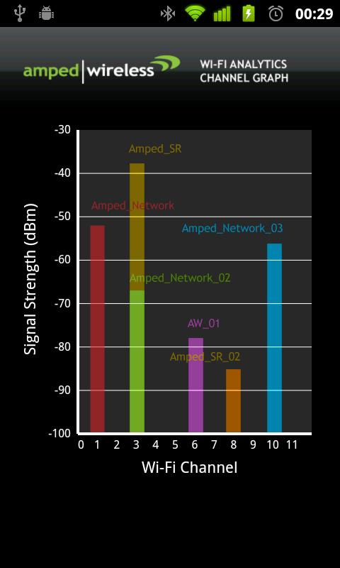
How to change the chart of FFT Power spectrum
Hi all
Could someone help me in Labview? I got a result as shown in Figure 1. However, I want the graph to resemble Figure 2 that we can define the range of frequencies for each channel in the y-axis and maintain the amplitude for the x axis.
How to change the chart?
Figure 1
Figure 2
I have the range of frequencies for each channel, which are:
Channel
Frequencies
Channel 1
2401-2423
Channel 2
2404-2428
Channel 3
2411-2433
Channel 4
2416-2438
Channel 5
2421-2443
Channel 6
2426-2448
Channel 7
2431-2453
Channel 8
2436-2458
Channel 9
2441-2463
Channel 10
2446-2468
Channel 11
2451-2473
Could only change the graphic on the front panel or have to change inside the block diagram?
Your answer is really appreciated.
Thanks & best regards.
-
It is better to define a waveform properties of scale before or after sending new data to the chart?
Hi, I wonder what is the best time to update the properties of the graphic scale waveform.
I'm sampling data every 15 minutes for 192 samples, or 48 hours. I want to draw these samples with x in absolute scale so the scale maximum x is time and x minimum scale at the time mode is x max in less than 48 hours (172800 seconds). I want also to intermediate-scale markers 6 hours apart and to be multiples of 6 hours. for example at 06:00, 12:00, 18:00. It works by using nodes of property but sometimes intermediate markers are on the hour 6 multiple and sometimes they are at 6 hours after the scale min marker. for example, 09:15, 15:15, 21:15. Is there a way to ensure that the intermediate markers are on the hour 6 multiples?
Thank you
Neville
Neville,
I don't think there is a function of the order of execution by using nodes of property information across your graph. If you are concerned about the speed of your VI, I would recommend writing to the property node before update you the chart. I believe that this will ensure that the chart will update only once: when the new data is sent to the curve, as opposed to the update with the new data, then with the new scale.

Maybe you are looking for
-
Whenever I open Firefox, I had a small window to appear and reports following error "TypeError; Components.classes['@ ['softage.ru/Skype FeExtensions; 1] is undefined
-
Restarts output when DAQmxWriteAnalogF64 returns an error
I'm using LabWindows/CVI to output analog voltages on a PXI-6723. My software works well until I try to write a value that is outside the range of the scale of this channel can handle. The call to DAQmxWriteAnalogF64 has legitimate returns error-20
-
DEP (Data Execution Prevention) prevents the host of opening process
I have HP Pavilion DV9704TX. Operating system is Windows Vista Home Premium.I have wireless internet and I use the wireless LAN to connect. Recently, I installed SP1 on my laptop. Whenever I turn on bluetooth to connect to the internet, I get a messa
-
HP wireless optical mouse Mobile
I have a HP Wireless Optical Mobile Mouse I would use with a laptop Sony 2007 which originally ran Vista and now runs Windows 8.1. I am able to install the driver, but the mouse does not work. Flashing red light on the bottom of the mouse indicates
-
Light green RPS on 3750 switch
Hello world I have stand-alone switch 3750. RPS led is green and light system is off. 3750TS env #sh all the The FAN is OK TEMPERATURE is OK SW series PID # status Pwr Sys PoE Pwr Watts -- ------------------ ---------- --------------- ------- --