Measurement of the ECG with MyRIO
1 can connect us monitoring ECG electrodes to MyRIO using the analog inputs?
2 and then using the software amplification instead of the amplifiers?
3. What is the best approach to collect values PQRST?
software: Labview 2014 with all modules
1. it depends on the output voltage of the sensor there.
2. you can amplify the signal in the software, but if the signal is too small, you may have a problem with the resolution, you would like to use the whole range of ADC in myRIO to see something useful.
3. I suggest an analogue input for this device and ensure that the signal is either already at the maximum range of the ADC or pre amplify before the digital conversion.
Tags: NI Products
Similar Questions
-
Measurement of the hysteresis with metal plate
Hi all. I have the task of understanding. I want to measure the hysteresis of elastic coupling. To the couple measure I two strain gages on 90 degrees (NI 9237 bridge half, II). After calculation, I now have the couple. In the other hand I measure angle of rotation of the motor with a metal plate with 52 teeth (gear). Angle of rotation I use input digital OR 9401. Hysteresis of bild, now I must on each tooth torque couted. I tried the example Multi - multifunction - Ctr Retrigg a generation sample clock Pulse Train HAVE but still graf give me the straight line. Can someone help me with this? Are there more better example for me, or clips in internet to show me how to do? Thanks before.
This is this case, the problem may be, the data acquisition card cannot rearm the fast enough triger either acquisition takes too long.
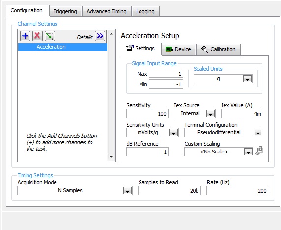
In the configuration of the screenshot I see you want to acquire 100 samples at 1 kHz. This means that each acquisition will be at least 100ms which might be too long for your application. NEITHER 9237 supports a maximum rate of 50 kHz, so my first sugestion would be to simply increase the sampling rate and see if it helps.
-
Measurement of the temperature with the PCI-6229
I was announced in an old thread and do not receive and answer, so I thought I try a new.
Link to the old thread: http://forums.ni.com/ni/board/message?board.id=250&thread.id=14920&view=by_date_ascending&page=1
I'm trying to measure temperatures using thermocouples using the PCI-6229 and I use two SBC-68LPR to make the connection. They are not reference on them joints.
After moving down from enugh to careful reading of the old thread I mentioned above and I think I knew what I should do. Here's what I do now:
Create a task - DAQmxCreateTask
Create a channel for this task - DAQmxCreateAIThrmstrChanVex thermistor
Create a number of channels of thermocouple for this task (DAQmxCreateAIThrmcplChan) using the cjcsource DAQmx_Val_Chan option and specifying the string thermistor as the source channel
Start this task - DAQmxStartTask
Get the temperatures - DAQmxReadAnalogF64
Stop the task - DAQmxStopTask
Disable the task - DAQmxClearTask
I have not yet hooked, but I doubt that it is the cause of the error.
A few more details (pardon my Delphi):
Create the channel of the thermistor
TmPcName: = ' Dev1/IA.19 ";
Secret: = DAQmxCreateAIThrmstrChanVex)
TcTaskHandle, / / task handle
@TmPcName, / / physical channel name
@TmChName, / / name of channel
-80, // Min range
80, // Max range
DAQmx_Val_DegC, / / units, ° C
DAQmx_Val_ResistanceConfiguration_4Wire, / / 2-wire, 4-wire, etc.
DAQmx_Val_ExcitationSource_External, / / source of excitement, external
1, / / value of excitement
9.376e-4, // a
2.208e-4, // b
1.276e-7, // c
30000); Resistance of referenceCreation of the channel of thermocouple:
TcPcName: = ' Dev1/ai23;
Secret: = DAQmxCreateAIThrmcplChan)
TcTaskHandle, / / task handle
@TcPcName, / / physical channel name
'', // Channel name
0, // Min range
1000, / / Max range
DAQmx_Val_DegC, / / units
DAQmx_Val_DegC, / / type of Thermocouple
DAQmx_Val_Chan, / / source CJC
25, / / value of CYC, so DAQxm_Val_ConstVal
@TmPcName); CJC channel, so DAQxm_Val_ChanIt looks like 4 scales is required for voltage excitement thermistor measurements.
In addition, it seems that external excitation is necessary in my case, PCI-6229.
Everything works if I use a CJCConstant. When I do this I use the same code to create channels of thermocouple, but I spend creating the channel of the thermistor. When I try to use a CJCChannel I get an error saying "value required is not supported for this property value," which occurs when I call DAQmxStartTask. I don't have no idea of what this message refers to and the best I can tell the properties that I've specified sense. The constant termistor are from actual thermistor, that I found on travailleursduweb.com.
I could also use some help to know how to connect the thermistor. Looks like I need to fab, a thermistor circuit myself, with a stable voltage to power the termistor and use a double-ended analog and reference to the channel.
Thank you
Mike
The error of thermocouple type was a type-o in the post. Thanks for catching it.
I think I found the problem.
I wrote a small program to test for Thermistors and I went to using the routine exctation of tension for a common routine of excitement (... IEX instead of... Vex). I had been by specifying a minimum value less than 0. I changed it from-80 to 0, and it works now. However, I got an error in division by zero, intermittently, when you read a thermistor channel. The error is not in my code. It occurs when you call DAQmxReadAnalogF64 for the first time and I'm not all mathematical related to this call. I'm still looking into it.
-
How to control of the screen with a list of scroll-able patch?
It's probably something simple I'm missing.
I would like to have control of the screen that displays a scroll-able list of all patches in my Concert.
Usually, our band adheres to the order of our list, and I can increment/decrement my way through the list.
But there will always be exceptions for last minute or queries or other changes.
I would like a list scroll-measurement of the patches with visible in large enough performance mode fonts so that I can find and select in the right order quickly, without going to Edit mode and set my old eyes strain to try to read the list of the patches.
I found this post looking for an answer to the same question, so I'm probably not much help (it would be really nice to scroll the list of patches with a hardware cursor!).
I play in a band where the set lists change constantly (or we take queries on the fly), so I just keep all my patches (i.e. song titles) in alphabetical order. A little something (you may already know), is that if you are in 'Edit' mode, type the first letters of the name of the patch to it.
I suspect it's one of those situations where there no place for developers some weird people would actually over a hundred patches in a concert.
-
How to measure the width of pulse with MyRIO
Hello
Sorry in advance if this is not the most appropriate forum. I'm not entirely sure if it's a more general problem of 'software' or the MyRIO-specific. I have searched the forums and found a few related topics but could find no one who help me in this context.
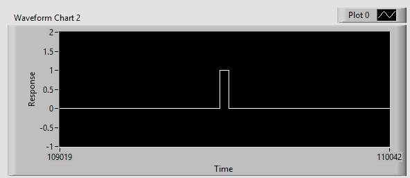
I'm trying to measure the width of a sensor pulse ultrasonic ping. It emits a signal conditioning - the time that it is high directly corelates how far is the object. Being new to LabVIEW I am confused as to how do I calculate the time it remains high.
I read that LabVIEW should not need to 'variables' as in python or C, for what is the best way to measure time, the signal is high? Normally, I'd go (new_time - old_time), but obviously I can't store an old time in LabVIEW as I would in python or C.
Other notes:
I have the sensor correctly ping echoing and I can see the blips on a chart and see a perfectly square wave valid.
To answer your question on how you would in LabVIEW...
While LabVIEW has not stated/named variables that you have in a language based on text, the data is stored on the wires. You can use the nodes as node registers or shift of feedback to store values between iterations of a loop:
(this will keep subtracting y (starting with 0) and store the result for the next time it runs)
LabVIEW also has functions in the range of mathematics/signal processing to make the detection of pulse on a waveform.
-
Measured values of task not aggreeing with the measurements of the test Panel
We read (with excitement) accelerometers using modules PXI-6254. Initially, we thought that we were see shift CC and we were and we filtered. Now, if we measure the sensor output at rest with an O'scope we read uV. For even if we read the channels with MAX test panels we also read some uV. But when we do the DAQmx tasks and look at the tensions of the task to MAX (same sensors at rest), we see readings of up to 25 or 30 mV - orders of magnitude higher. Can anyone suggest what may be the cause?
(I enclose a word with screenshots represetative doc)
Thank you
lmd2
How many channels are tailor-made and at what rate? What is the output impedance of the accelerometer or filters, you have between the accelerometers and the 6254?
It is possible that you run into error when paying. The specifications for the PXI-625 x cards has a chart showing the expected setting vs error track-to-track interval various sources.
A way to test this would be to slow down your sampling rate. If the error decreases as you slow down the sampling frequency, it's a good bet that you run into a problem of setup time.
Mark Moss
Electrical Validation engineer
GHSP -
Strange problem with measurement of the color under Mac.
Hello, I have a strange problem with measurement of the color under Mac. For example I create a gradient in Photoshop color 200 200 200 color 240 240 240. When I measure the color of the gradient with the Photoshop color measurement tool or with the built in OS X color measurement tool measured color is of 200 199 197 to 240 240 238. I measured the same gradient with Photoshop for PC and the values are OK (the same values that I create).
I don't know what the problem is, but I think that the colors that I create are the same I have measure after creating them and also values between Mac and PC. I appreciate much help or information you could give me that helps me understand what is happening here.
Thank you for your time
Marcelo.
Yep, you guessed it, evidence as monitor basically removes all profiling and just offer it right.
is it possible to make the OS X color measurement tool to measure the original color values
You mean the colors of paper - No., as I said photoshop filter your image through the profile document, proof of installation and the monitor profile. Why use Digital color meter for this though?
I don't understand what is measurement of color values that will change every time point calibrate it my monitor.
Because color values are "larger" what is on your monitor. Your monitor (via photoshop) makes only the best he can to display these values, which can be anything from LAB colors outside the range of your monitor - to the CMYK color. Calibration, it is the only way to allow your monitor to do this in any way accurately. (never really impossible) The monitors have a certain range and are only representations / would the REAL colors who is the holder of a document, with a profile. There's only one good reason to measure the monitor values so that is to build a monitor profile.
-
Measures of software right for remove mSata 32 GB drive cache to replace the HDD with SSD.
Hi, does anyone have instructions, or so point me to an article, to remove the disc from cache mSata original 32 GB configured to speed up drive HARD etc so the office strictly from the HARD drive boot can drive alone. I know that this implies the RST and possibly the BIOS settings. I'm looking for the exact steps that I had bad experiences removal (and adding) 32 GB mSata led cache in the past. System does not boot... Note I didn't need no guidance on physically remove the disk and for the curious once I have a clean boot of the only HARD disk I will clone the SSD (2.5 which I already have) so the 32 GB mSata is redundant and I would remove it completely. I am also interested by your experiences and/or complications in doing this. Thank you.
These instructions may be of any Dell desktop, the office in question is a Dell XPS 8700.
Hi all
Here are the exact steps I used to replace a HARD drive accelerated with an SSD without any problem. It will probably work on most laptops and Dell desktop computers. In my case a Dell XPS 8700 running Windows Pro 64-bit 10.
1 rapid Storage Technology, performance-> Disable Acceleration tab-> makes available.
2. use DISKPART to CLEAN the drive 32 GB mSata.
3. run msconfig.exe to set the mode to boot without failure, a minimum.
4 stop.
5. press F2 at startup to enter BIOS. Change to AHCI RAID. (probably not necessary, but I wanted that you never know what SSD tools may need).
6 mine starts in Mode safe very well and it has changed Windows 10 AHCI RAID drivers automatically.
7 run msconfig.exe to change normal startup.
8 re-boot (started fine normal start-up).
9. I then stop and removed the 32 GB mSata reader (you probably do this stage 4)
10 success, XPS 8700 AHCI HHD boots without any problem.
11. I then used Acronis True Image HD provided for free with the 1050 GB Crucial SSD to clone the 2 TB drive (650 GB used). Important do not use Acronis in Windows mode but create and boot from a bootable USB key. Community.crucial.com/.../172487
12 put the SSD in a basket of 3.5 and swapped the HHD with the SSD. Now, it starts in a few seconds and not minutes after a Windows 10 update!
It worked for me, but obviously not guaranteed to work for you...
-
Best way to measure accurately the activity of hiking on Apple Watch
I use my Apple Watch with watch OS 2.2.2 paired with an iPhone on ios 9.3.3 6 and ask what is the best way to measure the calories during the hike. I currently use the app to drive and walk outdoor activity type, but it seems that the market with more than 30 pounds on the back should burn more calories than the market alone.
It would make sense to increase my weight of 30 pounds (or whatever the weight of the package is that day) in community health for the market or is there another solution to workaround that would suffice?
It would be great if a later version of workout app had a hiking activity or hiking with a place to specify the amount of extra weight in a pack or vest or even just an option for additional weight to the open-air market.
Thank you!
tcpsoft wrote:
It would be great if a later version of workout app had a hiking activity or hiking with a place to specify the amount of extra weight in a pack or vest or even just an option for additional weight to the open-air market.
If you want to suggest that Apple considers adding that as a new feature, you can do so here:
https://www.Apple.com/feedback/watch.html
(You do not speak to Apple here - it is a community based on the user).
-
How to put in place measures in the application of health?
How to put in place measures in the application of health?
What do you mean 'the configuration steps? If you want steps if poster on the health dashboard, tap on health at the bottom of the screen data. Tap fitness. Tap measures. The value "Show on dashboard" on.
The health app is really more than one application storage and synchronization. You can't do things as targets for a particular metric. If you want to set a goal of step and follow it, use one of the many followed apps available that can extract data from health. Map My Fitness, My Fitness Pal, Jawbone UP and Fitbit (both can be used with the phone if you have an iPhone 5 or a later version). If you like to compete with others, the Club activities is fun.
-
The interface of the AVI with the PC using LabWindows/CVI
Hi friends,
I have a vector Network Analyzer Keysight Technologies / Agilent Technologies N5230A. I want to run with the LabWindows/CVI to measure channel 40 GHz. I want to interface the AVI with the PC using LabWindows/CVI. It is really essential for the measures, and I have no experience in doing these things. Would you please direct me to the best, easy as possible of this work? I'm really conscious of the fact that and thank you for your time and concern.
Mohamed
I have a vector Network Analyzer Keysight Technologies / Agilent Technologies N5230A. I want to run it with the LabWindows/CVI and measure channel 40 GHz. I want to interface the AVI with the PC using LabWindows/CVI. It is really essential to me, and I have no experience in doing these things. Would you please direct me to the track better, easy and correct these work? I'm really conscious of the fact that and thank you for your time and concern.
Mohamed
-
Noise measurement of an accelerometer with card PCI-4461
Hello world
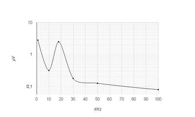
I'm trying to measure the noise of an accelerometer, except with a card PCI-4461.
First of all, I measured manually this noise with the help of a HP35665 signal Analyzer. I get something like this:
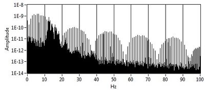
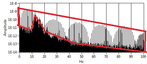
And now with LabView and the PCI-4461 map, I get this:
My question is: Whence this part? And how to remove it? (Since there is no with the signal Analyzer)
I'm using LabView 8.5.
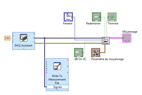
This is how I configured the DAQ acquisition:
and it's my VI:
Thank you in advance for help
Arthur
-
frequency corresponding problem with myrio!
Currently, I am working with myRIO and Labview 2013 to generate sinusoidal PWM signals.
When I created 'analogue output' tab myRio and connected to the Oscilloscope, oscilloscope waveform could not show me the appropriate frequency combined with a frequency that I gave in labiew. Is there a relationship between the frequency of "the"(myRio tap) of analog input between real-time rate? ". Otherwise, is it certainly possible to calibrate the frequency in labview? Please help me!
-
How to run code and to communicate between the computer and myRIO?
Hello
I am trying to create a colortracker using the myRIO. The system is pan tilt servo with a webcam. The project works well and is able to follow and move with the desired color. However, in order to continue the project, I want to ensure the system with another device for the perception of depth and want to use the host computer for webcam and image processing and the myrio to get signals for the servos. The idea is to connect two webcams directly to the computer usb ports and keep the myRIO connected to everything does time i.e. no wifi. Can anyone guide me as to how I would go about sending signals constantly between the computer host and myRIO?
I advise to use Variables shared Network-Published or network stream.
You can read about them both in the cRIO guide Developer: http://www.ni.com/pdf/products/us/fullcriodevguide.pdf
There are also examples for both in the Finder for example LabVIEW.
-
Analog control over the timing of myRIO MSP?
Hello
I'm new to myRIO and just got my.
How do you set the rate for similar samples of the port of an MSP myRIO?
For example, I would like an analog stream output 200ksps.
Place the block of OUTPUT ANALOG in a timed loop and runs only gives an output of 6.3 kHz frequency. (measured at the ao1 using a scope)
See the attached file.
I incorrectly use the timed loop? (.. .havent used before)
Or myRIO does needs some extra configuration?
Thanks for any help to what appears to be a very simple problem.
See you soon.
Hey, Carloman.
In this case the speed is limited by the software (OS, background process and especially the code LabVIEW) running on the ARM processor on the myRIO. 200 Ksps specification is for the hardware. If you need to write this young, you can use LabVIEW FPGA to write data.
One of the reasons why it is difficult to reach the 200 Ksps output rate of the side RT is because each iteration of the loop produces only 1 sample (the FPGA is configured for the only point of exit... a sample at a time). The perfect way to generate samples on the side RT and to write data to 200 Ksps is to build several samples each loop and use a FPGA personality that supports analog output buffer in memory. This allows to generate N samples each iteration of the loop and then send samples to a FPGA (FIFO) buffer that implements buffer and copy the data. I believe that it is coming in a future update.
For now, you can implement this architecture by creating a custom FPGA personality or you could do everything in LV FPGA.
Let us know if that makes sense.
Thank you!
-Sam K
Join us / follow theGroup of pirates of LabVIEW on google +
Maybe you are looking for
-
I try to install the 2013 VI Analyzer and LabVIEW 2013 SP1 is already installed on my machine. When it gets to the part of the installation that indicates it is being installed, it shows that nothing will be installed. It seems as if 2013 VI Analyz
-
Just bought a new computer with Vista. The ' Check for Updates ' button is disabled in Windows update and automatic updates will not activate. Anyone else had this?
-
I just bought the Linksys and with internet 80/20 1900acs delivery 15/10 on phones and the band of the plu 5 GHz of PlayStation 4. Tried resetting and still happens. No quality of service active. My laptop, wireless, is able to reach its full speed t
-
Whenever I start my computer this box apiers error in c/windows\system 32\nvmctray.dillmissing entry: nvtaskbrinit
-
DHCP option to set the controller IP for Access Points (Airespace)
Hello world. Does anyone have an idea to specify the controller using DHCP options. We use: -Controller AIR-WLC4404-100-K9 -AP-1010-AP-5312 poinst access -Server dhcp DHCPd ISC 3.0.1 Newspapers on DHCP server indicates that access points become the I