Modbus crc
Hi all
My query is about CRC Modbus RTU.
I know Modbus Library provided by OR calculates the CRC, but I want an event (boolean or int etc.) when the CRC does'nt transmitted and received are so that I can call it a mistake. and not to perform additional operations.
Am I missing something?
Kind regards
Robert
Also, if you run the library Modbus CRC function on a chain that already contains the CRC bytes, the output of the CRC of the function returns 0 if the CRC is correct and something else if it is wrong. Then you can just take the string, put it in the function CRC and do a = 0 on the output of the CRC of the function to get your Boolean value true or false.
Tags: NI Software
Similar Questions
-
Map of CRC-16 TR - M Communication, Modbus RTU
I'm writing the procedure for generation of CRC - 16 for Communication if card - M from TECO Electric and Machining Company. Here's the algorithm that they provide to generate the word of CRC - 16 (attached is my attempt to implement, I look forward to suggestions). Here are verbatim:
A. load a 16-bit register with FFFFH. Call it the CRC register.
B. Exclusive or the first 8-bit byte of the message with the low byte of the CRC 16-bit registers, put the result in the register of the CRC.
Register to shift of c. CRC one bit to the right (towards the LSB), zero filling the MSB. Extract and examine the LSB.
D. If the LSB is 0, repeat the procedure C (another change). If LSB is 1, exclusive or the CRC register with the value of the polynomial A001H.
E. Repeat C, D, until the eight shifts were made. Wile to do this, a full byte will have been treated.
F. repeat the procedure B-E to the byte following the message so that all the bytes of the message is processed.
G. when the CHILD is placed in the message, TI upper and lower bytes are to be swapped.
If anyone understands this, please feel free to tell me where I would not (see attachment).
See you soon!
jmcbee,
I have attached a vi that comes with the Modbus LV library. You should get the answer.
-
Control data DATAKOM DKM 409 RS485 modbus output
Hello world
My project is to control a furnace and im using DATAKOM DKM 409 with rs485 modbus output. in this project, I want to monitor data using labview. reason to do this, I use a RS 485 to RS 232 converter but when I connect them to each other and to my pc there is no recognition of the machine and when I want to use visa in BT it cant recohnie any device connected to it and gives me below error:
LabVIEW: (Hex 0xBFFF009E) VISA or a library of code required by VISA impossible situated loaded. This is usually due to a required driver is not installed on the system.
my converter is under this link:
http://www.securitycamera2000.com/products/CCTV-RS232-to-RS485-PTZ-converter-for-DVR.html
Please give me a guide about what is not going in my project. I really don't know why I can't config my port of visa and my source of visa is not recognized
thnks
ERFAN Shahsavari
Hello my dear all
Here is the answer and the consequence of my work:
1. in the manual of my legacy notes that we can choose 1 to 253 device id and I chose 240 but it was a mistake and I have the device between 1 32 ID value. (If I want to select more than 32 a Repeater must be used)
2. According to the operating instructions register addresses are between 40001: 40095 example 40068 and because of the structure of MODBUS RTD (device id, the function code, address of departure, number of registers to read registry, control CRC) I need to set the register addresses 40068, but it was a mistake and it was bad. The correct registry address is 68 no 40068. And in the structure MODBUS should I use 68 no 40068 or using the modbus library, that I must use 68 as registry address 40068 not.
Thanks for your guides
-
Hello
Has anyone used driver to connect to a device using RTU on RS232 Modbus labview?
I have a camera that I need to send messages and I tried to use the labview OR to that effect drivers.
I used 'Query.vi Mo series Master' to send a message.
But, I don't know what it would take as input in this vi to frame the message using the RTU Protocol.
Also, I wrote a program to calculate the CRC for an input string. I don't know where to give that as input for this vi add the CRC to the frame of the message.
The vi automatically calculates the CRC?
I am attaching the document for the device in which talks about pages 106-117 to develop an application to control the unit.
Can someone tell me please how to use modbus for this driver? The document in support of this driver gives me a lot of information.
Thank you
VJ
The modbus VI automatically calculate the CRC for you. Right-click on the inputs to the Modbus VI query and select Create constants. The constants will be the clusters for the necessary data. The key parameters are Modbus slave address, command, address,...
Note that registry modbus addresses may or may not be moved by 1. So address 1 in the manual might actually be the address 0 in the Modbus VI.
-
Modbus series write in a single register
Hi guys,.
IM new to labview (started back a week) and im trying to create a module VI (Protocol Modbus) for writing and receiving a single registry.
I worked on c# and here is the application (Modbus c# .png) that im trying to implement in Labview.
I went through the tutorials and downloaded the nimodbus library. There are many available in the library VI and I used "Init.vi series MB" to configure serial port settings (output baud rate, parity, etc.) and I was able to run it successfully.
Please guide me on how to send the Sub settings to write to the registry in labview. I tried to use "MB series Master query write only Register.vi" and 'MB Transmit.vi series' but im not able to make it work.
Parameters: -.
Save the address :-00 (top) and 7 d (bottom)
Value :-00 (on top) and 00 (low)
CRC:-19 (top) and D2 (bottom)Where is the register addresses the needs (upper and lower) to affix the modules of vi?
Where the needs of value (upper and lower) to affix the modules of vi?
If the CRC will be calculated automatically?
Thank you
KrishThe address is the registry you want to write to: enter 007D in that. (If it turns out to be wrong, try C 007) The controls are U16, if you enter the upper and lower values.
Holding the register corresponds to the data you really want to write. (I think that can be poorly named in this VI and could be confusing). You want to write 0 in there.
The CRC is calculated automatically.
It's all in the VI Query Mo Master series.
(I'm not familiar with the VI MB series pass.) Where have you seen that? Maybe it's a Subvi in the library.)
-
How to display records of entry into Modbus in hexadecimal?
I am connected in series to a relay, and by reading the registry entry to 1 address, I get 580 which is the version of the firmware of the relay and is therefore correct. Is it sort of, I could get the output as the full header modbus IE: (address: additional function: data: error code check/crc) for example: Fe, 02, 44, 80, 00, 02, F8, DC?
Also when I am trying to write to a single coil, which is the reset of the system, I don't know what address to use for the block of writing simple microphones. I know that the function is 5 and the operation code for this relay is 0001 but do not know how and where to use the code of operation?
Attached the VI is used to read the registry as well as documentation on the reset command and application Modbus for relay
Set your "String to write" command to the spell of display. Then type the hex values.
-
Modbus Toolkit NOR is not reliable?
I'm controlling a Watlow F4 in LabVIEW using the toolkit to add-on modbus. When I started to write this application, I used some modbus screws that I found in the devzone, but that he was not too keen on the use of unfamiliar code someone else. I thought that using of NOR would make things more robust. Instead, I am now meet delays and bad data reads.
I am running a diagnosis now, read a series of books about 40 and comparing the table resulting in a well-known data table. The toolkit OR failing to duplicate the right data within 5 tracks. I have received from the Commission on the screws have executed for, let me check... 96 iterations without error so far. What is the problem? Someone else has complaints about the modbus Toolbox?
Has anyone used tools Automated Solutions .NET (http://www.automatedsolutions.com/products/dotnet/ascomm/mb.master.serial.asp)? Or other 3 rd party tools?
Thank you
Ed K.
If you speak
http://zone.NI.com/DevZone/CDA/EPD/p/ID/4756
It is not officially supported, and there are a few bugs with it (just check the comments). The big one is that MB CRC - 16.v returns a u8 instead of u16. Fixing that is easy and will normally be your problem. You can try the other bug fixes if they seem as if they were relevant. The official way to use modbus is via the dsc module.
http://sine.NI.com/NIPs/CDs/view/p/lang/en/NID/1010
I use the first library, so I tried something else.
-
Hi all
I have a servo-motor brand Ezi-Servo, which operate by sending the command series for her.
The problem I've got is on CRC Checksum. I tried my best to do, but the result was not the same as the sample code they gave me.
Please check my code and my VI and show me what I'm wrong. I would appreciate.
Polynomial is x 16 + x 15 + x 2 + 1
Some examples of good result of the CRC16
6 A 04 01 00 - CRC16 = 0020
03 00 00 - CRC16 = 01 D9 B 0
My VI below, is
Hello
In regards to our result of offset by comparing the C-program. I already spoke with the support of the product.
The CRC algorithm is CRC 16 Modbus, even we used.
Cause we got wrong with the result is that they did is not calculated CRC of the whole package. they cut part of the outside (example: header, address etc.) and calculate only the data component.
If I appreciate everyone of you guys for helping me solved the problem.
Thank you very much.
-
Re: Internal error CRC on satellite
Hello
I'm trying to restore the operating system on my mother in laws equium. I say yes to erase the entire hard drive and it gives me the plugin screen of your power to say and that is to copy the new files, then I get a crc error internal to the Y then a different location each time (usually in music).
I tried to use another drive of toshiba and also just an os disc. I tried a disc hard diferent and also another dvd player.
Can anyone help?
Thank you
Clare
Hello Clare
Please don't get me wrong, but your ad is quite confusing.
Each Toshiba laptop comes with the pre-installed operating system and install recovery disc. New laptop models are supplied without disk recovery, but with the recovery image saved on the HARD drive and it can be used for the installation of operating system.It will be interesting to know what model of laptop do you have and do you use original Toshiba Recovery for the OS installation disc.
To be honest I don't know what to do, you mean under another drive of Toshiba or just OS disk.
It is not understandable that you think average with different hard drive and also an another dvd player.The whole story is extremely confused. It will be nice if you can provide more specific information.
-
I can not connect my P60 to the local wireless network at work. I have a good signal (the router on the same desk), but Windows just goes to "detecting network type" and then said that the network is out of range.
Atheros client utility shows that I'm not 100% crc errors and no packets received ok.
I tried to remove and reinstall the drivers and also the donwloaded later on the Toshiba site.
This indicates a hardware failure? I felt so I got the screen repaired and have not tried the wireless since.
Hello
You're talking an Atheros utility then I suggest that this software is installed on your operating system.
AFAIK the Atheros Client utility to configure your wireless connection.
In this case, the Windows wireless configuration must be disabled.
Please, go to the wireless options and disable the option use windows to configure my wireless networkGood bye
-
Hi all
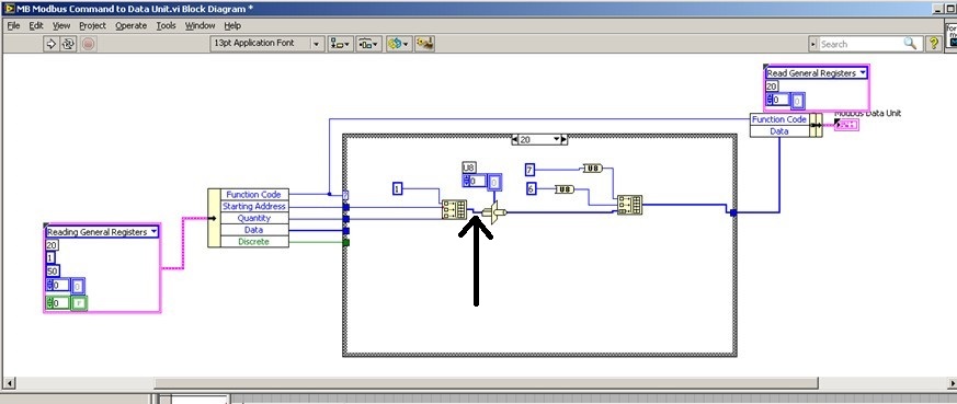
We try to add 20 saving file read function code in order to read the brief in bulk from PLC. We used the modbus for Labview library to communicate with the PLC with Modbus TCP/IP, but when I addes the code function 20 to the cluster of the MB Ethernet Master query entry reading registry Palette entry, the program displays an error. I'll be really appreciated if someone could help with this problem!
We hope all have a good weekend.
Best regards
Sophie
Actually... that is a constraint on the second entry to "build the table? ' It is difficult to tell from the image. If so, what is the data type of this cable?
That must be an array of U16s, because the "quantity" and "home address" are U16. However if the value '1' is a larger data type as U32, labview perhaps at upconversion of the whole table that would result in a larger data set than expected and could cause error 2. You can check on this?
-
I get an error CRC/LRC of a system half duplex 485 connected to a Watlow controller. I have the device set up in MAX for auto 4-wire and I have this code running on other identicle with number systems. Does anyone have an idea on what would cause such a mistake?
In most cases, I know that a 485 connection is a connection of 2-wire. You may need to assign MAX auto 2 son.
Kees
-
Is there a way to read only a modbus on request? I want to be able to click a button 'Get Data of the controller.
Also related, I just want it write on command. I currently have a trigger/relay for writing data, but I can't tell if modbus is always send the "write" command (using the previous value of the line) or not.
I'm reading through the modbus test data. It seems that additional orders would limit the sampling frequency, leading to lost data. If I read that data registers, the data have no recurrence. With other commands, I get up to 10 blocks of the same value.
Thank you.
You take the input module in a relay with option of data block. Only when you raise the output of the command, you will be allowing the flow of the module.
This average thagt unless you trigger the relay, the module will not process and ask for value
-
invertek modbus communication by car
Hi all
Seems modbus is a way to communicate with the disks for a long time. For me, and because we have a new machine equipped invertel drive P2 is new.
So, after many emails between invertek I couldn't so much as to communicate with the reader with their software. Only her entry to go to modbus.org
For their software, I use a converter usb rs485 and I use pins 4 and 5 (pc connection), but for modbus change for 7 and 8 (modbus)
Join is the manual for modbus for the driver.
My question is, what is the easiest to read VI (for now) of records and the way to the entrance. I need to input 03 (for reading), then the registration number?
Please help for the first step, then I'll build the complete software (I have now installed modbus library)
Thanks in advance
cpalka
-
ComBox MODBUS - difficult to write in the registers of the S.R.I.W.
Hey guys,.
I'm talking to a UPS (ComBox XW +) via MODBUS TCP. I can read the values of read only registers very well, and they line up exactly what I see on the interface of the web page they have. However, when I try to write a particular register r/w, I get an error of the incompatibility of function (-538172 using modbus smithd API). Also, when I try to read the register R/W, I always get the value 65535. This leads me to believe there something wrong with my configuration of device, but just in case, I thought that I would make sure that I wasn't doing anything weird in the code. Please the the image of the block diagram, as well as the manual that I use for the device in the attachment.
There is a small note MODBUS online as well:
http://solar.Schneider-Electric.com/wp-content/uploads/2014/04/conext-TL-using-Modbus-application-No...Hey Thomas!
Thanks for your help, however, this link is not available more when I try to open it.
In any case, this problem is resolved. I was just writing the bad slave ID! The other slave was present on the network, but it is card MODBUS is completely different, that's why I was seeing these weird values.
Maybe you are looking for
-
My Mac Pro with OS X 10.9.5 2009 and my husband of 2011 MacBook Pro with the same OS developed blurred finder windows today. These computers are not networked in some way. Basically, the finder windows are unusable because of the truncated graphics
-
Why did I paid $1 after that I entered my Visa information?
Hi, I just entered my information to visa payment info, after that, he get $1, I don't know why I have to pay?
-
"Signature" page is ok, but the Inbox etc is too smal for see and I would change it.
-
Yoga 2 1050f touch screen does not
OK, so I thought that all problems were gone after my last frost. now, I turned on and the touchscreen is unresponsive to a touch and I have no idea how I can restart lol
-
Satellite L500 - can I get all the instruments and the driver for Win 7?
good then I got this Toshiba Satellite L500 with Intel... its installed with Windows Vista Home Premium... The first problem I had with it was that the Toshiba programms stoped working and reformatting the drive and put it back, then I 'solved' this