Modbus read
I'm reading three registers of a Modbus slave unit operating from inside a timed loop. The timed loop is configured to run at 250ms intervals in the original application and that's why I won't be able to wait until playback is completed. So, I read every one registry, which allows a 250ms gap between each reading.
I just want to know if the VI that I coded will do the job? (Reading of a single register in a VI with Timed loop works fine) I'm particularly curious about whether referring to how I opened the VISA and using it is correct.
Thank you
Salvation of the crows and CC,
Thanks for your interesting alternatives in the treatment of the data conversion. Of course in this case the maximum is taken by scripture - reading for the Modbus and so this calendar conversion is not too critical.
But good course compared to the original way of stripping - reorganization and concaneting alternatives are very elegant.
Thanks again.
Tags: NI Software
Similar Questions
-
Is there a way to read only a modbus on request? I want to be able to click a button 'Get Data of the controller.
Also related, I just want it write on command. I currently have a trigger/relay for writing data, but I can't tell if modbus is always send the "write" command (using the previous value of the line) or not.
I'm reading through the modbus test data. It seems that additional orders would limit the sampling frequency, leading to lost data. If I read that data registers, the data have no recurrence. With other commands, I get up to 10 blocks of the same value.
Thank you.
You take the input module in a relay with option of data block. Only when you raise the output of the command, you will be allowing the flow of the module.
This average thagt unless you trigger the relay, the module will not process and ask for value
-
Using NI MODBUS - reading of several distinct registers
I'm using LabVIEW 8.6, with the NI MODBUS 1.2 VI library. I have a device which serves up to 50 records, all keeping the same format. I want to read about 20 of them, however they are not consecutive. (40010, 40015, 40017, etc.) Read Holding Registers VI gives me the opportunity to read consecutive registers beginning at a given address. On the other hand, writing several registers VI seems to me to write in an array of distinct registers. Is it possible to do it for the reading of records?
AZZOAutomation wrote:
I'm using LabVIEW 8.6, with the NI MODBUS 1.2 VI library. I have a device which serves up to 50 records, all keeping the same format. I want to read about 20 of them, however they are not consecutive. (40010, 40015, 40017, etc.) Read Holding Registers VI gives me the opportunity to read consecutive registers beginning at a given address. On the other hand, writing several registers VI seems to me to write in an array of distinct registers. Is it possible to do it for the reading of records?
-
Hello
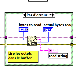
In the Advanced_Serial_Write_and_Read.vi we can find in the Labview example, in the part "reading" of the program, I have to put the right number of bytes I have to read in the memory buffer, and if I don't I always get a time-out error.
I want to read the buffer without putting the number of bytes that I read before. Any idea to solve this problem?
I have attached the VI.
Thank you
Peter.
Hello
What do you think is impossible, because the instrument you control needs to know the number of bytes, it must go back.
In addition, the entry "bytes read" is a necessary input.
Normally, when you send a command to your instrument, in the documentation of the instrument, you have all the information to determine the number of bytes to read.
Sincerely
-
Modbus communication with a piezoelectric dynamometer
Hello..!
I am a new user of LV and I try to communicate with a piezoelectric dynamometer in modbus RS232.
After you install NI Modbus Library, I created a master VI with labview 8.6 using these libraries and I can get communication with scale, these values are added in the registry U32Bit 1 and it's good, if I press a load cell, I can see the values exceed. (from 0 to 65535). Now, I want to show on the front the weight in KG, as the decimal separator, for a proper interpretation of the value for my client, so I added a block table to unbundle that I convert a value with I32Bit (-32768 a 32768) with a flag, but I don't see not all values...
I guess I did something wrong (conversion), I read a few KB, but I do not see a solution...
Can someone give me a link or information to show me an example to convert this value... ?
Thanks in advance for any help to...
Configuration of master VI:
Read now register
Address starting 2012 (query to get the net value of the load cell)
Quantity 1
Slave address: 1
RTU
9600
3 com
parity none
Can you post some examples of bytes you receive from the Modbus read and you expect that these values are? It's probably just a matter of the right of casting, or the number endianism, or operation of scale that must be done.
-
Modbus, writing in the registers by PID regulator
Hello
Can you please help... I'm new here
I try to use a registry read, send the value to a PID vi, then write in a register.
I've attached an example of using a temperature regulator.
I get errors whenever I try to connect using clusters, clusters, etc..
My material and comms are all good, I have values and all gauges reading ok, but it seems I can't work on how to manipulate the data through a vi of PID.
Your help is very appreciated.
Thank you
1 rearrange your functions so that your reading of data occurs before your writing of data. You can do 1 2 3 4. Right now your code run step 3 before step 1 and impossible to know where should go steps 2 and 4.
2. your writing log has an entry called registry where your worth is going. There is an entrance to U16. Your PID provides a DBL. You need to read the manual of the device know how to code the PID output floating point number into an integer. It may be a simple by multiplying by a factor of scale and he rounded to an integer.
3. your Modbus Read is for several records. You will get a table 1 d of readings, but it will not be 1 element. You can use the table to Index, and then together with setpoiint wire to feed in the gauge of multi-aiguille. Since you data will be an integer U16, you may need to perform a scaling to convert an integer in all that but it represents the temperature.

4. don't forget that you must connect your process in the PID function value.
-
I have a Modbus (VP Flowscope) instrument that I'm trying to interface with and I've never worked on before Modbus. I wanted to see if anyone had some tips to get this working soon.
I wrote the code using the NI DSC, the code on the NOR-Lab Toolkit (which is roughly the same as the DSC OR) and another download which can be found here:
http://www.NI.com/example/29756/en/
All of them fail with my setup, even if I think I can see a response from the slave device.
Attached are a few snapshots of my code and a screen shot of what I see on the oscilloscope. On the ground of the scope, I think that the second operation is a response of the slave, because if I change the settings (address, parity, etc.) then I do not see this transaction.
I got this job with the 1.2.1 MODBUS library, where you can dive into the code and see the bytes sent/received.
Once I realized my bytes sent were the same as what I saw in other programs, after a bit of work to clear some false errors (reading 00 what from VISA read IO error exception), I could see the bytes received were the same institutions.
-
Analog value read with DSC Module Modbus
Hi, I have a Delta PLC with an AD converter module. I use the four analog channels and in one of them, I have a thermocouple which displays temperature data on a microprocessor thermocouple meter. However, I want to display the data in Labview. The controller communicates with labview through the DSC Module of labview with success, but I am not able to read the data. Looking forward to your help.
Found the solution. addressing to the modbus master was different for this model of plc, so I looked up the address for delta plc Modbus and the analog read list has been a success on labview.
-
Point of Modbus DSC read does not correctly
I use 2013 LV 32-bit on W7 64-bit. I talk to an industrial controller with Modbus to Ethernet. My current software uses the interface modbus DSC, in which I define the bus Modbus itself within a library in the project, and then set each point Modbus as an address within this definition of modbus. Inside LabVIEW, you can then get the data Modbus via shared Variables. I am currently using the dynamic variable calls shared, rather than static variables shared. I have points that are Boolean (coils) and real, with a read-only and a read/write. In general, it all works.
However, there is a real read/write that acts funny. If I put a new value, or the industrial controller assigns a new value, the industrial controller Gets the new value. Variable motor shared on my computer gets even the new value, as can be verified by opening the Distributed System Manager. But LabVIEW continues to read the old value, without error. Other points of read/write work very well, and I have looked on the definition of the address several times and cannot find any reason why this should be different than the others.
Does anyone have any ideas why DSM sees a new value of a shared variable, without LabVIEW continues to get the old value? I watched the init for the dynamics of SV case, and I see all the options I can change to try to solve this problem. My next attempt will be to rewrite the entire auxiliary system so that it uses the most recent Modbus Library of NOR and ignores the whole thing of DSC. It will be probably much better for other reasons as well. I noticed that with DSC and the shared Variables, the first time that the program runs it starts fairly quickly, but subsequent executions can take up to two minutes to connect to the SV.
Thank you
DaveT
Never mind. I think I found the problem. A bug minor configuration in my own code...
-
Read Modbus register at a variable point number
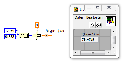
I am just reading for a Hart Modbus controller prolinx I talked to Prolinx, and established that my pressure values are coming from 40031-40032, my values flow from 40131-40132 each standard U16 values using LabVIEW code are:
I get a rather absurd number. I tried to reverse the tables and byte and Word-swapping. all to nothing does not. for register 31-32 bed 61919 LabVIEW and 16811 respectively must be combined to get something close to 82 + some change and records 131-132 i read 17054 and 61858 respectively which must combine to 79 and change.
I tried most of what I can find on there, but ask your question about the holes in this issue he can pop something.
Thank you
Mark
Hi Marc,
you are doing something wrong:
-
Hello
Currently, I can read data out of multiple using the attached VI DAQ devices by manually changing the address of the slave on the front panel that determines what slave to read the data. However, I want the VI to do it automatically for me instead of me manually by clicking on the buttons on the front panel to change the address of the slave. In other words, the VI should read data off devices 3 slaves and save them to a database of all the 1 second (sampling from 1 sec interval). I tried to use the structures of the case, timed sequences and delays, but I'm still not able to get what I wanted. My current VI is a modified version of a VI library modbus - 'MB series Master query read input registers'. No idea how to do this?
IM pretty new to LabVIEW, so don't kill me if im away here

Could replace the cluster 'Series settings' with the attached structure solve this problem?
The real deal will be just the value back to the default (1).
-Tom
-
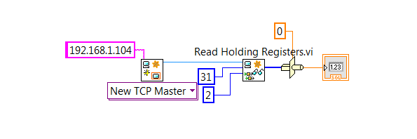
LabVIEW VI to read a meter of Modbus
Hi all
I'm trying to use LV with Modbus bookstores to read/write information to a Flowmeter Micromotion. The meter is connected to the PC via a B & B electronics isolated converter USB RS485. VISA see the converter very well. However, every time I try the meter reading, I get an error "VISA: (Hex 0xBFFF003E) could not complete operation because of the i/o error."despite all my efforts. " Can't understand you my problem, maybe it has to do with how I address the meter? I posted my code for any future reference.
Thank you, it turns out that my camera had been incorrectly wired. I can now read the information I need from the flow meter.
-
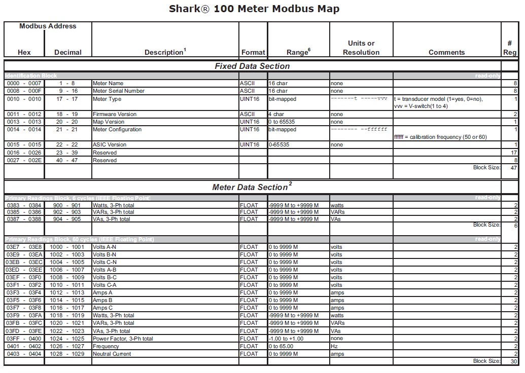
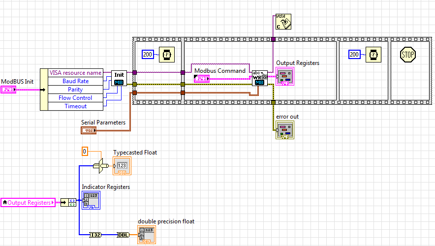
I'm having a problem with loan any floating point number correctly in the distance a 100 Power Meter shark.
I can read sucessifully a block of records containing the name of meter and the serial number as a 16-bit characters.
For example when I read records 1-16 on the map and flatten them into a string, I get a string of work completely returned.
When I try and holding registers A 1012-1013 (AMPS) I get really funny to read numbers when I converted to a float.
Here is my code so far
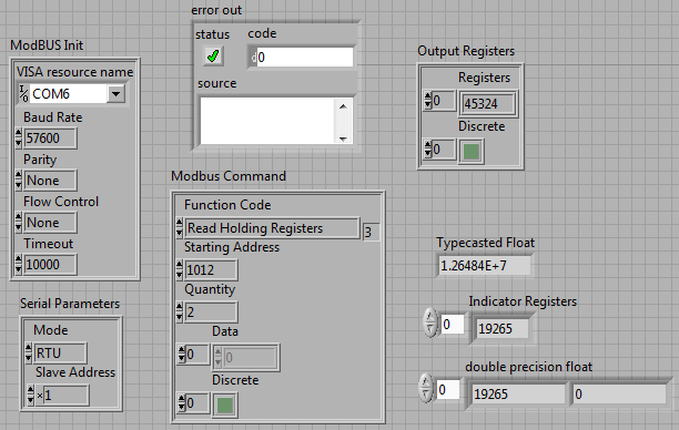
With my front panel settings:
Expected value, I'm looking to have returned: 11.11 amps
but
When I use an indicator to read registers: 19265, 0
Same value when I do a conversion
When I do a type cast to a float: 1.26484E + 7
I tried some different combinations such that read that a single register and join the numbers, both in order to big-endian and little-endian, still no luck.
Help, please!
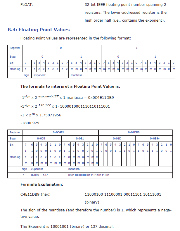
Here's the modbus float definition according to the owner's Manual:
Also, I saw that the Toolbox Modbus has sometimes behaving strangely of the off-by-one-register (so you need to actually ask a different address to get the desired data) and that some devices have a behavior even more strange out-of-one byte, while now you're out of half of a register, and you will need to ask for more records and then reorganize the bytes by taking a byte of the previous register or end.
-
Hello
I am trying to contact a Watlow F4D controller on a room using RS232. I use a cable converter USB-series and NI Watlow F4D Serial Driver.
The code of error-1073807339 occurs in:
Read in F4.lvlib:Utility MODBUS RTU Watlow VISA receive message-> Watlow F4.lvlib:Utility Register.vi reading
I don't know what caused the problem. I am able to see the cable converter USB-Serial OR max. Please see the pictures for more details
Thank you
Felix
-
Reading the words of temperature controller fits using Modbus
I'm working on a project that involves the use of a certain number of temperature controllers, Omega CN 7823 s. The Protocol of communication for them is RS485 Modbus ASCII or RTU.
I had a bit of trouble getting a job of communicating. I think I do everything correctly in terms of setting up the initial communication parameters (baud rate, parity, etc.), but have been unable to properly read the values. I am able to write values to operating records, but cannot read them. When I try to read (using the code 03), the result is simply a multiple of 256 (if I try to read registry 1001 H, which is 4097 in decimal form, I get a result of 256).
I'm running in ASCII at a speed of 9600, 7-bit data length, parity and 1 stop bit.
Any help would be appreciated - I am attaching my VI and the manual of the controller.
In the end it turned out that I had to create a property node to the VISA Instrument and specify the mode series RS-485/2-Auto. This allowed the computer read the response from the controllers of temperature instead of simply reading the message that was sent to them. I wish I had discovered this day 1, 2 or 3 to work on this problem, instead of the day 5.
Maybe you are looking for
-
My windows Vista, SP2 doesn't have windows fax and scan lilsted.
Original title: windows fax and scan. My windows Vista, SP2 doesn't have windows fax and scan lilsted. I followed the suggestions of look in System 32. The required file IS NOT THERE! How dan I installed? I need this program is not compatible Vista
-
I try to run microsoft word from a file on a storage disk.
I use microsoft outlook 2007 and need to communicate with people who only use microsoft works. I found microsoft works on my laptop hard drive but do not know how to activate it. All files in microsoft works are .dll extensions. Is there an extens
-
using the color laserjet 3600n - I want to print in black and white, but it prints black and white negative. * beep *.
-
I created Windows Theme Pack. I don't know how I send it to the personalization Gallery of Windows (http://windows.microsoft.com/en-us/windows/themes)
-
What is the latest version of Windows 7 Ultimate?
What is the latest version of Windows 7 Ultimate edition starting from 07/12/2012?