Multi-threaded custom device
Is it possible to create a custom multithreaded device? I want to create a client-server architecture, somewhat like the http://zone.ni.com/devzone/cda/tut/p/id/3098 example in a custom device. The only difference would be that I would like to make the series of read/write in the high priority task.
Thanks for the help!
-Ryan
Hi Ryan,
This should be possible if you use a custom asynchronous device. The curls will then run in their own thread and do not affect the execution of the primary control loop. Make sure that there is enough time sleeping in your loop of high priority. Note, however, that put communication series in the loop of high priority will negatively affect your determinism.
For more information on the Veristand engine and the custom device types you can choose one, please see the following:
Understand the VeriStand engine
Tags: NI Products
Similar Questions
-
The value of custom device entry
Hello
In fact, I create a custom (asynchronous) device that controls a climate system. It consists in adapting a functional code LabVIEW to create custom device. Unfortunately the LabVIEW code uses a lot of FGVs that act as input and outputs at the same time (this means that the system can change the value of an entry).
So, I would like to know if there is an easy way to set the value of an entry in the custom device engine code. I tried the following without success:
- Written in the FIFO of the entrance channel.
- 'Set channel use value' of the API of NI VeriStand-> I get the error 307970.
Yes, is there something I can do to facilitate the creation of my custom device? instead of "Rethinking" all the code which is a real pain in the * the complexity of it?
Thanks in advance.
Pen
We solved that by using part of inllne to only update the channel and postponed the real asynchronous threads treatments with exchanges of data through FIFOs.
++
-
Choose CPU Inline Custom Device
Hello!
I wonder if it is possible to assign a Custom inline device to a specific processor. I know it's possible to do a custom asynchronous device.
I developed a custom device inline, calling an asynchronous vi. I can affect the heart for the asynchronous part, but how to choose the kernel for the part online?
Thank you...
Hello, I guess that the online part is executed from the thread VeriStand, then the kernel is involved by the call control loop and cannot be changed. But maybe I'm wrong?
-
Urgent: continous recorders of NIDAQmx and other instruments with multi-threaded vc ++
I'm working on a software with vc ++ to control several instruments including a NO-DAQmx6289. For example, the features of the software.
1. communicate with data acquisition card (card data acquisition) and continuously acquire data from several channels at a frequency of 1 kHz.
2. connect with function via port RS232 1 generator, sending triggered bursts to the real-time features generator change state Ultrasound (G_usstatus) variable.
3. connect with optical switch via RS232 2 port, send signals to switch between the two input channels (0,1) and six output channels (2,3,4,5,6,7) to the specified user to sequence and time interval (default: 150 ms), real-time change the channel connection variable (G_optchannel).
4. in real-time, record data and the corresponding ultrasound status and connection status of optical channel in a specified file use for later analysis.
I use multiple threads to make data acquisition (1-wire), control of the function (2 wire) generator and optical switch (3 wire). I also need save data acquisition of data and the corresponding ultrasound status and use the connection status of optical channel in a specified file for later analysis. I use the following codes to read data continuously.
Sub DataCollectionWin::ConnectDAQ()
{DAQmxErrChk (DAQmxCreateTask ("", & taskHandle));}
DAQmxErrChk(DAQmxCreateAIVoltageChan(taskHandle,"Dev1/ai0","",DAQmx_Val_Cfg_Default,-10.0,10.0,DAQmx_Val_Volts,NULL));
DAQmxErrChk(DAQmxCreateAIVoltageChan(taskHandle,"Dev1/ai0,Dev1/ai1,Dev1/ai2,Dev1/ai3,Dev1/ai4,Dev1/ai5,Dev1/ai16,Dev1/ai17,Dev1/ai18,Dev1/ai19,Dev1/ai20,Dev1/ai21,Dev1/ai6,Dev1/ai7,Dev1/ai22","",DAQmx_Val_Cfg_Default,-10.0,10.0,DAQmx_Val_Volts,NULL));
DAQmxErrChk (DAQmxCfgSampClkTiming(taskHandle,"",1000.0,DAQmx_Val_Rising,DAQmx_Val_ContSamps,60000));DAQmxErrChk (DAQmxRegisterEveryNSamplesEvent (taskHandle, DAQmx_Val_Acquired_Into_Buffer, 50, 0, EveryNCallback, NULL));
DAQmxErrChk (DAQmxRegisterDoneEvent(taskHandle,0,DoneCallback,));DAQmxErrChk (DAQmxStartTask (taskHandle));
Error:
If (DAQmxFailed (error))
{
DAQmxGetExtendedErrorInfo (errBuff, 2048);
MessageBox (errBuff);
DAQmxStopTask (taskHandle);
DAQmxClearTask (taskHandle);
return;
}}
Int32 CVICALLBACK EveryNCallback(TaskHandle taskHandle, int32 everyNsamplesEventType, uInt32 nSamples, void *callbackData)
{
char l_optstatus_s [1] l_optstatus_e [1];
char l_usstatus_s [1] l_usstatus_e [1];/*********************************************/
Reading DAQmx code
/*********************************************/
If (! m_bStopTracking)
{
l_usstatus_s [0] = g_usstatus [0];
l_optstatus_s [0] = g_optstatus [0]; Switching State optical before reading the data of 50 * 15DAQmxErrChk (DAQmxReadAnalogF64(taskHandle,50,10.0,DAQmx_Val_GroupByScanNumber,data,50*15,&read,));
SetEvent (hEvent);
l_usstatus_e [0] = g_usstatus [0];
l_optstatus_e [0] = g_optstatus [0]; Status of the ///optical at the end of the reading of the data of 50 * 15If (read > 0) / / / save data in an exl file specified by "datafile".
{Indicator = 1;
for (i = 0; i<>
{(/ / fprintf(datafile,"%d\t",i);}
fprintf(datafile,"%c\t",l_usstatus_s[0]);
fprintf(datafile,"%c\t",l_usstatus_e[0]);
fprintf(datafile,"%c\t",l_optstatus_s[0]);
fprintf(datafile,"%c\t",l_optstatus_e[0]);
fprintf(datafile,"%.2f\t",data[15*i]);
fprintf(datafile,"%.2f\t",data[15*i+1]);
fprintf(datafile,"%.2f\t",data[15*i+2]);
fprintf(datafile,"%.2f\t",data[15*i+3]);
fprintf(datafile,"%.2f\t",data[15*i+4]);
fprintf(datafile,"%.2f\t",data[15*i+5]);
fprintf(datafile,"%.2f\t",data[15*i+6]);
fprintf(datafile,"%.2f\t",data[15*i+7]);
fprintf(datafile,"%.2f\t",data[15*i+8]);
fprintf(datafile,"%.2f\t",data[15*i+9]);
fprintf(datafile,"%.2f\t",data[15*i+10]);
fprintf(datafile,"%.2f\t",data[15*i+11]);
fprintf(datafile,"%.2f\t",data[15*i+12]*5);
fprintf(datafile,"%.2f\t",data[15*i+13]*5);
fprintf(datafile,"%.2f\n",data[15*i+14]*5);
}
fflush (stdout);
}
}
}Now the problem is the data acquired with daq card does not match the corresponding registered swtich optical status (G_optchannel, which specifies the light connecting channels). High readings expected certain status really appeared in any other situation. It seems that there is a misalignment of the multi-thread data. Because the optical switching State passes to 150ms, so I put DAQmxRegisterEveryNSamplesEvent to be trigued each 50samples, which means 50ms with 1 kHz sampling to avoid missing the changes. I also check if there is any change of status during the DAQmxReadAnalogF64, by registering l_optstatus_s and l_optstatus_e, which are actually the same. I wonder if this is because the data are first registered in the buffer. When the software starts reading, at that time, optical swtich status no longer reflects the State when the data was recorded first. Is it possible to fix this? Thank you very much!
kGy,
I'm glad to hear that you are progressing with your project. Timestamp data are always a bit tricky, because the process of querying a counter on the CPU is done asynchronously with the acquisition of your DAQ hardware. However, your equipment will ensure that the relative chronology between samples is consistent (in your case, the data will be sampled every 1 ms). And since you have changed your program as you are now all samples acquired reading, you know that each sample follows the previous 1ms. So, if I were to implement this I think that I take an initial horodotage when I started the task and to calculate the timestamp for all samples following this timestamp (timestamp SampleN = (*.001s + horodotage initial N) or timestamp SampleN = timestamp SampleN 1 +. 001 s).
I would go to do that, rather than the timestamp of the end of the reading for the following reason. As I mentioned previously, the reminder of your reading will run when the OS is planning. Therefore, it is possible that it gets delayed or does not exactly in phase with the acquisition of hardware, and make adjustments to your code to handle this problem. However, when you're timestamping there is another thing to pay attention to. It's the fact that your hardware has a FIFO where sampled data can accumulate before getting transferred to the memory buffer that reading from (for example if the bus PCI were busy when the sample was acquired). Now assume that the stars aligned against us and get the following:
(1) the operating system is busy with other things, and our reminder read gets delayed a few ms.
(2) at the same time, another device connects the PCI bus (or part of the data path between your device and the memory used for the buffer).
(3) one or more samples is momentarily blocked in FIFO of the device.
If you were to read data timestamp at the moment, your timestamp would reflect the data in the buffer as well as data that was flying in the FIFO of your device. However, you can only read data in the buffer. Thus, time stamp applied to data that you just read would be a millisecond or two later they should be. Suppose that on the next read reminder, this condition has cleared up itself. This timestamp taken here would be accurate, however, you will need to return some additional samples (those who were stuck in the FIFO last time). If you backcalculation your timestamp at this stage, I think that the timestamp calculated for these ecaple timestamps calculated on the previous reading. It wouldn't be ideal, nor would it reflect when the data has been actually sampled.
One of the remaining challenges is how exactly the start of time stamp feature. To do this, I would like to add a call to DAQmxTaskControl (taskHandle, DAQmx_Val_Task_Commit) before calling DAQmxStartTask. This step will advance the State template DAQmx as far as possible without actually starting the task. This will help to DAQmxStartTask as soon as possible. Now, before the appellant beginning or immediately after, I would take my initial horodotage (perhaps timestamp before and after and take the average). Then I would use this original time stamp and my sampling rate known to calculate timestamps for all the rest of my samples.
That got a bit long, but I hope it has been helpful.
Dan
-
Custom device error VeriStand-307603: no specified main page?
I get the 307603 error when I try to add a custom device, I developed a VeriStand project on a client computer. The message error window States:
«Error 307603 occurred at Custom Devices Storage.lvlib:Initialize New Custom Device.vi > Custom Devices Main Page Data.vi Storage.lvlib:Get.»
Possible reasons: NI VeriStand: the required custom device doesn't have a specified master page. Contact the creator of custom feature to correct the error. »
I get this error when you add the device custom VeriStand on my development computer; only on the client computer. I tried to copy the custom device built on top of the client computer and the custom device of source based on the customer's computer. I also have three other devices custom that I developed that work fine on the same computer, so I don't know why it does not work. I checked the specification of the build configuration to ensure that the VI home page is included in the source files, and to generate test preview shows only the custom device LLB and the XML from the file in the build directory, as expected. The XML file is also oriented the correct path for the homepage VI and the GUID in the XML is the GUID file matches in overall search GUID variable. I can't think of anything to check.
Development computer:
Windows 7, 64-bit
LabVIEW 2011 SP1
VeriStand 2011 SP1
The client computer:
Windows XP SP3, 32-bit
LabVIEW 2011 SP1
VeriStand 2011 SP1
Everybody knows such a question or give me additional troubleshooting tips?
I got it to work, but I don't know exactly what the problem was. I made a copy of the part of the XML file that adds the device custom menu right-click and commented of the original, then edited the part I copied it to give the device custom a different name in the menu. It worked fine on my development computer at the time I made the change, so I thought it was OK. I just went and restored the file in the original version and now it works on my customer's computer.
-
I have problems with of the Subvi after the use of customized device model
I used to start my machine personalized customized device model and I got success in the deployment until I started to do more complicated the Subvi. I am currently trying to convert low FPGA and high ticks to the duty cycle, but for some reason when I add it to the RT VI "Data read of HW" driver, it seems to cause a downtime... ideas? Is a circuit agree? I have added a time delay but I am still having problems. It is a device online, so I'm suspicious of it hogging resources, but am not sure.
Attached images are meant to be read like this:
1. the case of the RT pilot ReadDataFromHW
2. it's the Subvi calling ToDutyCycle SIMStimPWMSubVI
3 ShiftRegister.PNG is inside the Subvi.
As a robotician I celebrate early and often (usually by a failure or two...), but it seems that the answer was to transform fundamentally the While loop for a loop with a count of 1 and then remove the additional elements to ensure that each shift register has that one and then right click on the shift registers and convert at the Feedback node...
I was able to deploy to VeriStand as a custom device and it runs and calculates the factor of use with no problems. WOOHOO! Where - what is celebrate button! -
How to integrate model of custom device controller
Hello
I now live a labview including 18 sub controller model, and I am trying to run this controller on RTOS VxWorks, through customized device model.
1. when I tried to run a model simple controller (ex, a controller with 3 ~ 4 void / screw) on RTOS VxWorks, I just put simple controller in
RT Driver.vi model, and then the build and deployment succeeded. 2. then, I did it with my model of labview in the same way above controller, but I couldn't even build my model controller labview. I don't know why, but the build process stops at the initialization stage. I think that this problem will appear when there are more than 3 ~ 4 sub vis are added under the custom device project.
Any ways to use a model of controller labview instead of just put a model in
RT Driver.vi? Now, I managed to build my model labivew, I saw the light of the compactRIO blinked, which measn the connection is ok by CAN - Bus.
But it's still weird and not possible to build my model at a time. In addition, cannot again build the custom devcie just before successfully built after the addition of two functions simply.
In any case, the solution to my problem is as below.
For example, my cruise controller written in labview consists of 3 simulation systems arrive.
Each system to arrive includes several subsystems.
First, create the model after adding one of 3 major subsystems. (In this case, I never had errors in the construction of models of labview)
Secondly, if the first step is ok, add one of the other 2 systems come in the custom device and then build again.
Thirdly, add the remaining subsystem in the custom device and establish the entire model and deploy it to the target.
With three steps above, I can still build devices customized successfully.
-
Why my custom device break only when VeriStand trying to run it?
Hello
I have a custom device, he worked for some time now, today, I made a few changes to add some features more and now VeriStand tells me the RT pilot is more executable.
I have not change my build configuration or add any functionas that could bring in an external DLL, or something that could link incorrectly.
Any ideas of how I could go on this shrinking. The problem is that when running in VeriStand. Built LLB has no problem, the source of the development has no problem, it's only when VeriStand tries to deploy there is a problem, so there must be something that is not bound correctly Yes?
The system isn't RT, it's just deploy on Windows using a SMU.
I am not sure the exact cause, but I ended up simply remove parts of the code piece by piece pilot to refine what was causing the problem. It turned to be a VI of debugging I used several times before in various projects, but which contains the string "call" LabVIEW primitive, but set apart from that, it's just a simple string manipulation. So I don't know if it was just a few cases of random edge that occurred when running under code basic LabVIEW VeriStand clean, but for some reason, he broke the driver VI.
So, solved the problem, but the cause, I can't really say.
-
Read VeriStand channel from inside the custom device that are not part of the custom device?
Is it possible to read VeriStand channels from within a custom device VeriStand (RT Driver) that are not part of this custom device?
For example, suppose I want to be able to configure a channel in my custom device to always be twice the value of a string of material that my user selects (I know, better/more simple ways to do this, but this is just a simple example
 ). Can I do this from the device custom without programmatically create a mapping of the system? (I've done this before and it is messy and VERY prone to error of the user).
Thank you!
good point
the channel ID (U64s) are not the same in the engine config of vs. Instead, you must set 'references to dependent item' in the config and then get these references in the engine.
See the source jarrod linked, which makes it
-
execution of the RT custom device screw driver
Hi all
I'm building a custom device in which I expect a user input. (user provides entries on the home page of the custom device).
Once the entry is expected on this basis I read the file-specific data and creating channels and article.
Previously creating channels and article I in the initailiazation code. But now that I'm waiting for user input I can't create these channels during initialization (reason is before getting the input channels will be created which I don't want. My creation of channel depends on the intervention of the user).
If this logic of formation of channel I now write in pilot RT VI with my main logic of the reading and writing of the channels. For this I just want to know what exactly is the RT pilot VI begins its execution?
If the RT Vi driver starts to run after adding the deivce custom veristand and after giving the user input and then my purpose will be resolved.
I hope I explained my question correctly.
The pilot begins after the definition of the system is deployed. I don't think you can add strings in VI driver. Nor do I think that you want, because you won't have an interface for them in the system definition. Without a channel interface, i.e. mapping, how do you get data in and out of them? I think your plan to create channels based on user input and data configuration are fine. I suggest that you implement in the homepage or pages on the main page.
-Steve K
-
How to detect the channel delete event in a custom device
I am creating a custom device and want to detect when you press the button Delete (X) in the system browser. This is so I can increment or decrement a counter in a folder (where the channel is under). I saw no option in UserEvent loop options. How do I detect that a channel is deleted?, I'm sure it's easy, but I can't seem to understand.
Thank you!
I recommend usually do not do that... If you can avoid it. For example the parent folder can do if everything is just a child get point-> the size of the array to count channels rather than storing a property that could get out of sync. I always try to design my devices do not store the property values for things I could go get.
That being said... Sometimes you don't have that. You want an actionviondelete: https://decibel.ni.com/content/docs/DOC-30447
-
Adding custom device VS programmatically
Hey everybody,
So I was wondering if there is a way to programmatically add a custom to a homeless GUY in VeriStand device. I have a program that runs through tricks of calibration and after it's done I want to automatically add a device tailored to the Homeless. So far I found only a way to get an up-to-date list devices custom - cannot add a.
Does anyone know how to do this?
Thank you.
I assume you are using the definition of system .NET API to change the homeless before deployment.
In this case, there is a constructor for a custom device that takes the GUID of the homepage. Once that is done, use the AddCustomDevicemethod on the node CustomDevices of the Homeless.
When you have the custom device reference .NET (the object) you can configure it with calls .NET as add channel/section and set properties. Although, given that most of the custom devices have initialization VI who made the most of it, you can call initialization VI, in fact if you want. To do this, get the NodeIDof the CustomDevice object and passing to the initialization of VI connector pane.
I hope this helps!
-
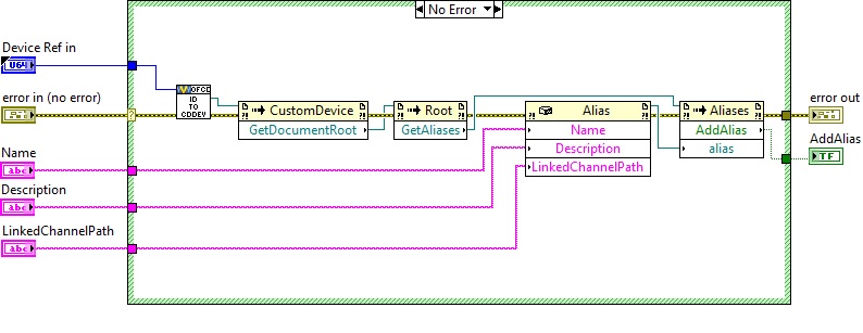
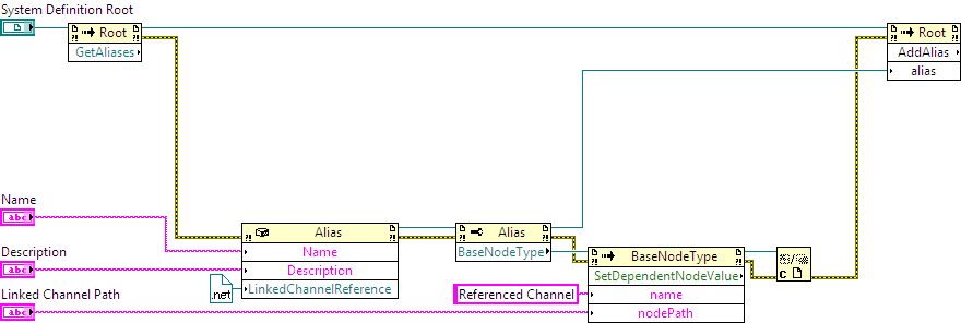
create an alias for a custom device page
Is there a way to create an alias for a custom device page?
I wish that a button on the home page of my device custom (in solution system Explorer) allow the user to create an alias and linking this alias on a channel of the system. My Vi is the following:
This VI returns the following error:
"Error 1172 to error creating instance of aliases in the assembly NationalInstruments.VeriStand.SystemDefinitionAPI.Alias, NationalInstruments.VeriStand.SystemDefinitionAPI, Version = 2012.0.1.0, Culture = neutral, PublicKeyToken is a6d690c380daa308, (System.NullReferenceException: determined reference is not set to an instance of an object.).
Is there a solution?
Hmmm... good point. You can change my original solution to configure the alias using the basic underlying storage system node type. It should work regardless of the type of channel. As for your second question, custom devices written for 2012 should be recompiled in 2013 of LabVIEW with the support of 2013 VeriStand installed. You don't have to change your code, but you must recompile the LLBs.
In this workaround, you start by creating an alias that links to nothing. Then, you update the alias to set the DependentNode property, which connects it to the channel. You should not do it this way, but this will work around the original bug.
-
Best way to pass the name of the e/s DAQmx channel Veristand 2011 Custom Device?
I'm building a custom device that will run a DAQmx task on the target of RT.
I use VS2011 and alsoSimple custom device tool, which, at this point I'm not sure if it can work under VS2011...
I created the fine libraries and custom device (a PWM input called InputPWM) has added to the Explorer from the system. Running it returns the following error when I deploy:
-----------
LabVIEW: Type VI reference is not part of connector of VI.
=========================
NEITHER VeriStand: Open VI reference in Custom Devices Storage.lvlib -> pen device reference (Interface HW) .vi-> Custom Devices Storage.lvlib:Initialize Device (Interface HW) .vi OR VeriStand Engine.lvlib:Initialize Inline Custom Devices.vi-> NI VeriStand Engine.lvlib:VeriStand Machine.vi engine-> Engine.vi NI VeriStand Engine.lvlib:VeriStand-> NI VeriStand Engine.lvlib:VeriStand .vi engine Wrapper (RT)
c:\NI-rt\VeriStand\Custom Devices\InputPWM\InputPWM Engine.llb\InputPWM RT pilot VI.vi----------------------
On the console, it says that the error is 1026, LabVIEW: Refernece VI is not valid.
I suspect that a potential problem is that I used a DAQmx e/s in the Configuration.ctl and the InputPWM RT pilot VI.vi in the framework can not deal with this type. So my questions:
-What is the easiest way to pass the names of e/s to the custom device? For a quick test, I could go to hard code, but a more generic solution would also. Should be based on the address for the e/s MAX? Do I have to create the ctr under the DAQ hardware in VS?
- or said by the way, is there a way to review these screw frame to see where the questions is, as you would with LV - RT?
THX.
L.
If you use the tool of easy custom device, just put everything you need inside the cluster configuration data and these data will be in the home page of the custom (for the user to set) device and be available at runtime in the RT device custom code.
You could have them type the name of the DAQ card and have an array of names for the channels to use. You then create the task running. or something like that. You like.
-
Asynchronous custom device fails to stop
While I was developing a custom asynchronous device, I came across a problem with the cancellation of the deployment of the .nivsproj I created to test the custom device.
The custom device would send the error: -307730 Error Message: NI Veristand: one or more asynchronous custom devices did not close correctly and has been abandoned by the Veristand engine.
I decided to do some troubleshooting for what could be wrong with the custom device by creating a separate custom device using the custom device model. I left completely intact model and it has deployed to our machine pharlap. When I canceled the intact custom asynchronous device it gave me the same error as above.
I use Labview 2010 Professional version 10.0f2 development system, NI Veristand 2010 for a complete system of development and deployment of the .nivsproj on a licensed machine Pharlap.
Sorry for the late reply.
Zach-H by using simple device custom you provided I was able to create a custom asynchronous device that was able to stop. This allowed me to insert instructions printed in the two devices to help out what was causing the unit to raise an error when stopping.
The culprit seems to be the NI VeriStand - Get loop Type.vi. The type of loop is never defined in the initialization.vi or the main.vi of the device model tool customized. So, when the RT pilot ran VI.vi the Type.vi loop get it would exit always false for the clock of the device to use and never use the correct name of the device clock. Without the name of the unit's clock he would never get a reason for reactivation.
I forced the vi to use the clock of the device listed in the custom device model tool and I was able to shut down properly.
TimothyA, you are right about the features of the measuring device. Even with the error of abnormal termination, the meter continues to operate normally after each deployment.
Thanks for pointing out the problem with no channel being added to the measuring device. I'll make sure the custom device I develop handles the case where no channel, input or output, are added.
Thanks for the help.
Maybe you are looking for
-
Given that I have updated to IOS 9.3.1 my iBooks PDF documents are uploaded to the cloud so that they can be shared on multiple devices, however when I rename a PDF, it comes back to the original name every time iBooks is updated. Anyone who has si
-
Serial number invalid to my Web site
I tried to enter my serial number on the Web page of my Support for my laptop and it says invalid. I also tried the automated system and it fails? Why I can't get support for a laptop that is less than six months old?
-
I have a HP Pavilion Elite e9250t desktop PC and I want to upgrade my video card
I have a PC desktop, HP PAVILION Elite e9250t with the specifications below. What graphics card can I go to? I currently have the Radeon HD 4650 with 1 G memory in the form of video card. I want something more grand, better and faster to run Borderla
-
Original title: windows media problemsWhy do my windows media sometimes not recognize that there is a disc in the drive when I am trying to burn music on the disc,
-
code device Slimtype dvd a ds8a2l 19
Hello I have Compaq Presario CQ60 and can't play and form of media in the cd/dvd drive. He returns constantly with the error code 19. I've done several things to try to solve but nothings working. # Help, please!