NEITHER series modbus libray
Guys,
I've been using the modbus series library NOR but the way I use is just to read a few integers periodically (from PLC). But now I must read as 2000 integers after 5 hours ' experience. you want to enlighten us?
Thank you
Modbus commands can read 100 (maybe 125) records at a time. How is important the info? You might want to look at adding checksums to the data in blocks of 99 records plc. This way you can ensure the integrity of data by recalculating checksums inside labview. It depends on what you are doing. How long the test data will be available and how much time do you need to see the results? The RTU mode is the fastest way to retrieve data. You could loop through the reading of 100 records in the blocks and increases the starting address each time. If you must store these results for historical purposes, the DSC module would be the best way to recover the data with a program of opc server. Record the results in the database of the Citadel.
Tags: NI Software
Similar Questions
-
Error 1073807346 series Modbus
Hello world
I am trying to acquire data from a microcontroller Infineon XMC 4500 with Protocol Modbus Series 9600 8 N 1; I also use a USB-RS232 converter.
When I read books I get an error 1073807346 ("the given reference of session or object is invalid"). In particular, the error appears in the functions of reading records and read of input registers.
I checked all possible solutions of document suopport, NOR in relation to this kind of error.
Someone at - he never tackled this problem?
I also include an excerpt of selection VI.
Thanks in advance for any advice.
Andrea.
One or more of your events are not passing the name of the resource through the register shift. You have chosen by default if Unwired. The default is a blank resource name.
-
How can I change the address Modbus to Modbus IO server programmatically?
Hi experts,
I use a cRIO 9076 that is configured as a server IO slave Modbus to Modbus TCP communication. I have always used the same Modbus address to configure the server of e/s and it has never been necessary to change so far. So I was wondering if there is a way to change address Modbus IO server programmatically, after it has been initially configured?
Thank you
Volker
Hi Volker,
There is an Express VI, that lets you create or change existing servers of e/s Modbus programmatically createand configure the Server IO. Once you set up like Modbus, you will be able to provide the address programmatically.
In regards to the address - you are right in that the Modbus address configured in the configuration of the server is not really used with Modbus Ethernet. According to Modbus specifications, the address is used when a network connecting Modbus Ethernet to a secondary network series Modbus via a bridge or a bridge. The specs say that the address 0xFF should be used on an Ethernet network. For more information on this topic, Please see page 23.
Hope that helps!
Best regards
-
Error 6010 Modbus Exception code: 10
Hi all
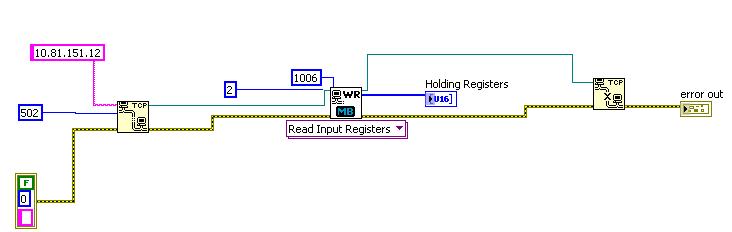
I need assistance with the modbus library, I just downloaded and since I am not an expert in modbus I have trouble using it. Basically, what I want to do the right is now read two input of a device (address 1006 and 1007) slave registers; using .vi MB Ethernet Master query required registers (poly) reading. All I get is an error code 6010 MODBUS Exception: 10. I saw the MB Ethernet example Master.vi to compare with mine and see if I was missing something, but I was not able to solve the problem.
I put a screenshot of the block diagram.
Please, someone tell me what I'm missing!
I only didn't series modbus, modbus Ethernet, I can't be sure. But with modbus series, you have certainly set the address of the slave. This cluster has a "customer ID" which seems to be that it should be equivalent to an address of the slave.
-
Modbus tcp read holding registers return not requested quantity
Background: I have a client using ELAU motion system - they record data with records they want to be able to read on a cRIO match with some analog FPGA data (I have digital handshaking going on for this).
LabVIEW 2010 SP1
cRIO-9074
With the help of the library of VI of MOdbus.llb OR communicate with the other system. I can open the TCP communication without problem and actually get SOME records, but not ALL registry data, I want to read.
I want to do is read the registers individual operating 330 U16 values. I know how the data are split to represent different lengths (i.e. most of the data items use 2 records number represent a 32 bit). I want just to read all of the individual records and analyze the data in another VI to convert it to other data types.
I provided the .vi MB Ethernet Master Query (poly) with the starting address for the first register, then the amount of 330. The polymorphic instance selected is "reading record keeping. The array returned by this VI via 'Holding Registers' is only 74 elements and not requested 330. I have no exception code and no error in LV. Is there some intrinsic limit, i.e. the number of Holding Registers that can be read?
I do not use the (not sure if necessary) MBAP header entry.
Thank you.
Simple solution once I dug in the series MODBUS/TCP protocol protocol documentation out there via Google.
History of the modbus function series is the limitation that carried over TCP - the maximum amount of bytes in the pack a data can be only 256 bytes. So I was limited to approximately 125 ~ records at a time.
256 bytes is 2048 bits. The use of the 16-bit registers which gives maximum 128 registers. I went with 125 followed making easier totals.
-
error:-1074130544 using the PXI NI 2569 map
Hello
I use the testbed 4.1 for the execution of the sequences. I use NI 2569, 2529, 4070, 6229, 4110 PXI cards in my NI 1045 chassis and I use my own COM server for the test bench. The COM server has the implementation to call the driver API provided by OR for different PXI cards. Now, I have improved my versions of all my PXI cards drivers. My driver versions are currently
OR Switch: 3.6
DMM OR: 2.7.2
NEITHER series: 3.3
NEITHER Daqmx: 8.6.1
OR Visa: 4.3
Traditional DAQ: 7.4.4 (inheritance).
I used to use versions of the drivers such as:
OR Switch: 3.0
DMM OR: 2.5
NEITHER series: 3.0
NEITHER Daqmx: 8.0
OR Visa: 4.3
Traditional DAQ: 7.4.1 (inheritance).
Now, the question was when I called you my code niSwitch_Connect() function, it allows to connect the switches correctly and returns a value when I was with older versions of the driver. But after upgrading my driver version now I get the 1074130544 error a few times, that is, the niSwitch_Connect() is able to connect the switches, once successfully but later if I try to call the same function for various switches most of the switches is closed successfully, but a switch gives the error.
Please let me know how I can do about it.
concerning
Krishna
Yes, you are on the right track. There must be a main routine, a piece of code that calls the two procedures that you have described. It is probably a good idea to log in this common piece of code and pass it as a parameter to these two procedures in two files separate .c, for these procedures to be used.
Best regards
-
Circular buffer with reference
I create two measurement systems that will enjoy air with instruments 13 and 10 respectively. I communicate with instruments through the series, MODBUS TCP, voltage and current. In order to synchronize the data of different instruments (which have their own data rate) in the stream, I need basically a circular buffer by instrument. I wish to add to each buffer circular instruments in a loop for each instrument and have a timed loop that records the data in a file by reading all the instruments circular buffers. Circular buffers must also be able to give me data that are not the most recent data.
How can I create a circular buffer that I can add items to a loop and read another looping? I would prefer something but who uses a reference that I can pass both the loop of the instrument (producer) and save data of loop (consumer), like the queue works in Labview, I don't know how to implement this in a good way.
Use LabView 2010 Fall edition...
Thank you
mrsound
Native queues in LV 2010 allow you to create a circular buffer if you are using the antiderivative of Lossy Enqueue.
Warnings:
- You must specify the size of the queue when get everything first, if you can not resize dynamically.
- To play the buffer, you can use the primitive that returns the queue information and wire a T in the items back? entry (very important to remember it). This will create a copy of the data in the queue.
-
How to read data from OM - 62 temperature/humidity data logger in LabVIEW?
Hello
I have an Omega OM-62 temperature/humidity data logger I want to communicate (initialize recording, reading/writing data, stop recording) through LabVIEW 8.6. The OM-62 is connected to the PC via a type B USB-miniUSB connector, and I have provided "Omega Recorder program Interface" on my Windows operating system. I called online DAQ support Omega but I was told that data recorders low level like this have not provided capabilities of LabVIEW, which I fully understand.
My question is why I have to use their program to communicate to this device? If I knew the syntax program them used to connect to the device, why can't I use through VISA? Do I need to build my own LabVIEW driver from their supplied driver?
Python is easier to apply to this scenario solution?
How can I see the code "Omega Interface Progam recorder" on my Windows operating system is using to communicate with the OM - 62 sensor?
I just want to know how this could or could not work because I think I'm missing some concept in my understanding of programming LabVIEW/novice. It would be easier to run my LabVIEW program and their program at the same time, but I just want to understand it at a deeper level.
Curosity killed the engineer occupation,
Zach
P.S. I have attached a few driver configuration information, but I have no idea if this is useful.
Unless the manufacturer provides a kind of programming interface or API to communicate with the device that you have trouble with your own software interface to it whether LabVIEW or Python or something else. This could be in the form of a driver dll, Protocol series modbus (etc. etc. etc.).
If it is not condition / available and you really need to communicate with the device, you will need to look at using something like a sniffer USB/driver (software? hardware?) to try to intercept communications between their software and the device. You can then use this information to try to understand what the commands it sends and the responses received and how to convert data.
Once you have that until now... I don't know what options are willing LabVIEW for control of USB device, but a proposal, I would say that you would need either a driver USB low level or you have to write your own driver in another language and that call from LabVIEW.
-
There are differences in supported features of firepower for the series 2 and 3 materials. Is there a clear vision of what devices are series 2 and 3 series which devices?
Material series 2 are the oldest brand devices Sourcefire. They were all end of 2012 sales or more.
They include the following models: 3D500, 3 D 1000, 3 D 2000, 3 2100, 3 D 2500, 3500 3, 3 4500, 6500 3.
All other dedicated NGIPS devices can be considered as the 3 series.
(Modules ASA power of fire and any new firepower 9300 and 4000 series is in a separate category and neither series 2 or 3).
-
London Lenovo reliable Service - Bios serial No. Update. Help
I recently bought via ebay a X 220 Tablet described as factory re-built (and I think it is). It works and everything would be fine, except that the BIOS is not a serial number and the number of the machine. These none of the drivers, downloads and dignostics will register on the machine that the research shows that these figures have questioned the pilot missing settles.
I have contacted the seller and I try to create the factory re-furbish details and go this way to see if I can get the back numbers but I think that I can not and the only way is to get a new motherboard installed and make sure that information is installed this time.
I contacted the technical support of Lenovo who cannot help you because there is no guarantee (neither series/product number).
Two things: -.
If anyone can help with the details of a service agent in London (South/West) reliable that exists and can help. The two officers that Lenovo Tech gave me could not help on the X220T or were "not available".
Or is anyone know of a technical solution/person/service that can help - work via the Lenovo Web site is not very productive.
Thank you very much
Yes, the Committee has its own serial number and this is what is needed in the bios.
Without a serial number of machine, it raises the question of why the jury was changed in the first place? Why was the machine serial number and removed model number? This label has not just dissipate. It is not any OEM that I know that works on any machine that does not have a serial number.
If the device has been damaged and the Board of Directors and the bottom of the case had to be replaced, then the bottom of the original case must have been included in the sale. Maybe it was an oversight, perhaps not. There is some responsibility involved in a repair if it wasn't. I had to replace a low case several times and I still spent some time scratching this label with a razor blade and attach it to the new deal. Anyone reputable service would do the same thing.
I'm sorry to have to go through this for a good machine.
Dave
-
Modbus series write in a single register
Hi guys,.
IM new to labview (started back a week) and im trying to create a module VI (Protocol Modbus) for writing and receiving a single registry.
I worked on c# and here is the application (Modbus c# .png) that im trying to implement in Labview.
I went through the tutorials and downloaded the nimodbus library. There are many available in the library VI and I used "Init.vi series MB" to configure serial port settings (output baud rate, parity, etc.) and I was able to run it successfully.
Please guide me on how to send the Sub settings to write to the registry in labview. I tried to use "MB series Master query write only Register.vi" and 'MB Transmit.vi series' but im not able to make it work.
Parameters: -.
Save the address :-00 (top) and 7 d (bottom)
Value :-00 (on top) and 00 (low)
CRC:-19 (top) and D2 (bottom)Where is the register addresses the needs (upper and lower) to affix the modules of vi?
Where the needs of value (upper and lower) to affix the modules of vi?
If the CRC will be calculated automatically?
Thank you
KrishThe address is the registry you want to write to: enter 007D in that. (If it turns out to be wrong, try C 007) The controls are U16, if you enter the upper and lower values.
Holding the register corresponds to the data you really want to write. (I think that can be poorly named in this VI and could be confusing). You want to write 0 in there.
The CRC is calculated automatically.
It's all in the VI Query Mo Master series.
(I'm not familiar with the VI MB series pass.) Where have you seen that? Maybe it's a Subvi in the library.)
-
wt210 GPIB driver for modbus series
Hello
I work with a digital power of yokogawa wt210 meter that has only a connection series (db25).
I downloaded labview drivers and uses a modbus interface to communicate via GPIB.
Thus, between the serial port to set modbus modbus GPIB for pc USB wt210 (4899a) interface.
Max recognizes the 4899a, but does not see the power meter. Any ideas on how I can use this driver for the powermeter?
Thank you
Hello
You can use the interface RS-232 of the WT210 or, if it is installed on the instrument, the GPIB interface.
As Dennis said no. MODBUS.
Download the examples on the site of Yokogawa and read the manual of the instrument.
-
NEITHER USB-6008 outputs in series to generate 10 V
We wonder if it is possible to connect the AO0 the AO1 as a series voltage source that generates 5 + 5 Volts?
The datasheet is not say, do or not, but he says they are independent.
Worst case being short, one of the outputs short-circuit if the ground is common?
-
NEITHER 9237, map of the c series
Yes, the change of measure may mainly be due to the precision.
I think that load cell specifications contain details of precision. It is usually in % of the maximum nominal weight.
Trust that helps
-
Satellite T135D-S1328RD - this series exist?
I searched for information on my computer (which is a Toshiba Satellite T135D-S1328RD), but I can't find it anywhere. I've been on the help panel, try to type, but an error occurs.
Follow-up of my series of the computer does not work neither. T135D-there no option in the choice of your computer in the list.
So I ask: where can I find it?Some settings are on the Internet, of course (for example here: [http://www.cnet.com/laptops/toshiba-satellite-t135d-s1328rd/4505-3121_7-34025428.html]), but I wish I could get professional assistance according to my computer on page of Toshiba.
I will not add that my computer is from Japan, but the same - no info about it can be found on the Japanese page.
What is the problem with this series?> I searched for information on my computer
What information are you looking for?
> What is the problem with this series?
I m a bit confused now. How to understand this issue?
Obviously this laptop model is designed for the Japanese market only if you won't find it on any other Toshiba support page.Otherwise, install Windows on your tongue, set it up and have fun with it. Where is the problem?
Maybe you are looking for
-
Bootcamp does not start after upgrade to Mac OS Sierra
10 Windows fails to start after the update of the Sierra. Mac Mini end of 2012. Volume can be locked and dirty. Paragon NTFS is installed. How can this be repaired
-
I want to format an external drive if I use it as a backup he wipe my drive hard mac
I want to format an external drive of 3 TB of Samsung, will erase my hard drive on my mac and store all my Mac hard disk?
-
REF of HP envy 17 3D 2199ef: LS592EA #ABF and support of windows 8
Hello Do you have the Envy 17 3D ref 2199ef: LS592EA #ABF will support Windows 8? and when driver will be available? Is it possible to use the SP58812 for the AMD radeon HD 6850 m switchable graphic? The 2199ef of Envy 17 3D were sold in France until
-
Why my Acer R7 touch keyboard appears in Chrome and IE, but not other applications?
I am running Windows 8.1, with the latest drivers and updates. My touchpad works when using Chrome and IE, but not other applications. He has never had this problem until today.
-
result::failure-104, deploying a file bar
When deploying a file to blackberry Z10 bar, I get the following error of blackberry-deploy systematically Info: Send request: installInfo: Action: installInfo: File size: 566071Info: installation...Info: Treatment 566071 bytesNews: Advance of 50%...