Output voltage continuous to the DAQ card provides a discrete signal
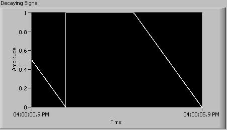
I'm looking at the exit of a continuous decaying signal as shown below.
(For now, let's assume that I must leave the Fs sampling frequency: 1000 and #s: 1000)
In the loop where the signal is generated, I inserted a block 'Wait (ms)' so that iterations would maintain the good timing. If this is not the case, the speed of the iterations would be too fast. Although, when I measure the output to the BNC connector, the actual output is in discrete steps, which depends on the speed of the iteration. (for example, for the signal preceding with freq = 1/4 Hz, the result would still be 1V for two seconds, 0, 5V for a second and 0V for a second, then repeat)
Is it possible to fix this?
Before I tried this method, I had used the output of Wizard DAQ, which had no need of me having to insert the "wait (ms). But the problem with this method is that there is a delay between when the program has sent a message and when the output BNC connector has received the signal.
I guess that the second method not released by discrete steps due to the buffer that is maintained in the wizard. I tried to have some sort of buffer to the first method, but could not because of lack of experience, I guess. If I could also, it seems that I could introduce a delay once again, which is undesirable.
Any help on this would be appreciated. I will attach a copy of the article that gives me bad.
Thank you.
Mike
As I said, the filter must be set up the EQUIPMENT. Just as an anti-aliasing filter on an analog input must be done at the hardware level, so a reconstruction on an analog output filter must be implemented in hardware.
Sometimes robust filtering is necessary, but in general a simple RC works very well. Google 'Filter RC' or "low-pass filter" to get examples and design equations. Often the hardest part only is coming with good places for mounting of all.
Mike...
Tags: NI Software
Similar Questions
-
Acquisition of data using the DAQ card
Hello everyone
I need assistance with the acquisition of data of the generator of signals through DAQ cards. I plugged the signal to the SCB-68 generator where the analog inputs of the generator are connected to AI CH5 and AIGRND of the Terminal Board. Then the output of the block is connected to the DAQ card. The maximum sampling frequency of the card is of 250 kech. / s. The problem is for reason that I am not able to see the waveform on the labview. I looked at other examples to find the problem, I am, but I am not able to understand this. I want to be able to choose the sampling frequency. I attatched my code as an attatchment for you all to help me know what the problem is. Any suggestions will be appreciated.
There is no task! You have not specified any hardware (i.e. your data acquisition card) anywhere.
Here's a suggestion. MAX aperture. Find your DAQ hardware. Open a Test Panel. Implement a continuous sample of N Points to some sampling rate. Press Run and convince yourself that you get the data.
Now, while remaining in MAX, to create a task, using the same settings. Call for example something sensible ("MyFirstDAQTask" is not a good reputation).
Now, go back to your code. Eliminate the first two functions DAQmx. Wire a constant task to the DAQmx Start feature. See the little triangle down? Click it, and it should show you the tasks he 'sees', the only one should be the task that you created in MAX.
Note that 'Samples Visible' is now 'hard coded' in the task. To get its value back out, you need to put a property node Timing DAQmx after the task start and pull on the quantity of the sample, samples per channel (which, for reasons that escape me, is a Dbl, you need to convert to an I32 before importing it into the while loop).
Bob Schor
P.S. Thank you to join your code.
-
Recommendation for the DAQ card
Hi guys, =)
I m currently developing a project in a gas control, where I need Messure tempertures and be able to open and close a valve.
My implementation are 4 termocouples and 4 relays to turn off the valves and...
I was hoping if someone could help me choose a card of data acquisition for two things. where she has 4 analog for
thermocouples and 4 digital (5v) output 4 relay. and be able to use them on the same card DAQ, USB PCI o preferably. or
use a map of data acquisition for entry and one for exit.
Thermocouples type K are...
TNX in advance...
Sincerely
Luis Alonso
Hi Luis,.
How current are required by the relay? Is the combination of a cDAQ-9174and NI 9211 , NI 9401 sound like it might meet your needs? You can also focus on devices that have integrated relays, such as the NI 9481 or PCI-652 x.
Brad
-
selection of the daq card to get the angular position of 6 motors with encoder
can you suggest me best daq card to use 6 positions of engines as outputs using encoders attached to the engines. I'll use single window for each engine. Or what can I use a single window for all the coders of engines?
Hello Prabhakar7117,
You need a counter for each encoder. Because you are going to use 6 encoders, you should get a DAQ hardware with 6 or more counters. Take a look at the PCI-6624 or PCI-6602. Another option would be a CompactDAQ chassis with modules that are able to access counters. Take a look at them.
KB which cDAQ Modules can be used to access the counters of the shipped?
Best regards
Alina M
-
How to give input to the DAQ card three times
Hi all...
How to assign three channels of entry (as Dev1/ai0, Dev1/ai1 and ai2/Dev1) DAQ card at the same time?
Rd,
Ganesh
BMETTENT wrote:
Hi all...
How to assign three channels of entry (as Dev1/ai0, Dev1/ai1 and ai2/Dev1) DAQ card at the same time?
Rd,
Ganesh
Use Dev1 / ai0:2?
-
Hello
I'm doing a tension of 3-story ramp. One who goes from 0V to-1V can-1V to + 1V and finally wear the voltage of + 1V to 0V. The main feature is that I try to sync input only a channel for the median ramp. I get the expected input but my output voltage on the oscilloscope is not correct. The entry and exit and goes a box NI USB-6229. On the oscilloscope, you can consider the following issues:
1. There is a gap between the end of the 1st ramp and the beginning of the 2nd ramp
2. once the main finished once, ramp voltage immediately returned to-1V and again another ramp until it reaches 0V, then levels out for another short period of time
3. the cycle then repeated from the beginning, completely missing ramp 3
If all those who think they might help in any way, I would appreciate any input. If someone tries the attached program: I used these settings: entry rate = 1000; #data points = 200; DT = 0.0005
-Kyle Shiel
If you want to copy your ramp of 3 floors without any pause between steps, you must accumulate the entire waveform (all 3 steps concatenated) and write in your output task at once (similar format This example, but no need to start and you need to replace with your own generated table waveform).
I would just at the entrance to the beginning of the analog analog output task. You can use the DAQmx Trigger Start.Delay property if you want to wait for the 2nd phase begin to acquire, or you could simply acquire all 3 steps and analyze what you need.
Best regards
-
Visualization of more values on the graph of the DAQ card
Hello
I acquire a Signal using the data acquisition card, the problem is that I can view only a few values on the graph of a waveform. Guide kindly of me if I want to see the points more on the graphical waveform, what I would do in my programming window.
Concerning
I think that you just want to use a TABLE instead of a chart. A graph has an associated history, so that it shows more that just the last data series acquired you and wrote to the curve.
-
How to use a switch connected to the DAQ card as a source of events in a Structure of the event
Is easy using a switch on the front panel as a source of events. However, I like to use an external switch electrician on my card for the acquisition of data (NI PCI-6229) as the event source in the Structure of the event. Can anyone help?
Happy New year to you too!
Attached is an example in BT 8.5
- It uses the time-out loop (running every 100ms) to simulate your reading of the data acquisition card.
- A shift register is used to keep track of the previous value of the switch.
- When a change of the switch is detected, the user event is raised and the display will show the new State.
Running the vi with activated highlight performance can be useful.
Steve
-
Average value in a second a series of signals from the DAQ card
Hello
I'm trying to average signals in one second of my DAQAssistant.I am using a shift register to add all signals in a second interval and then dive out of the turn register by the number of iterations of my time loop (which I think should be the total number of samples per second-1). But when I studied the value of i from inside while loop by placing an indicator it always returns a value that is equal to my (sampling rate of DAQAssistant) / Samples as follows. This means that the average value I get something wrong, it is the average value seems within the reach of the signal I get.
I wanted to use an array to store all the signals in a second, but I might have to increase the samples up to read the value in this case it will not be a very efficient way to store 500 data in a table.
Any reclassification help how to get mean value over a cycle would be greatly appreciated.
Thank you
This is because an iteration of the loop returns a type of dynamic data that is under the hood an array of 100 samples. The loop runs 10 times because you stop the loop after 1 second, only lasts only 1/10 of a second because she the 1000 Hz divided by 100 samples. That's why I + 1 is equal to 10.
Now you have 10 bays (buried in the dynamic data type) added. Divided by 10 gets you the average of these 10 tables. But this average is always an array (buried in DDT), but when connect you up to the average indicator, is to return only the first sample of average average array which is why your average seems essentially functional. However, the averages of the other 99 data points (x iterations of the loop 10) are lost.
You would be better off away from the DDT. Just work with arrays. Add the 10 tables to each other. Now, you'll have an array of elements of a thousand that you can all wire to the average function in the range of statistics. You won't have to worry about count the iterations of the loop, in summary and dividing.

-
Output 2 length of time different voltages while recording the current of one of the outputs
I create a vi that generates output 2 waveforms of voltage different (AO1 and AO2). These signals is different in duration and number of times it will be produced. AO1 must take place several times while AO2 is running her first time. I also record the entry of AI1 output in AO1. I have attached a vi that I thought it would work. I thought it would be good to have the AI/StartTrigger initialize the acquisition and the output voltage. However, this arrangement results in an error. The error I get is-200802. Am I going about this all wrong? Any ideas?
At first glance, I see some problems with your code:
-You arecalling DAQmx writing before calling DAQmx Start. The departure must be called before writing.
-You have two tasks of analog output. Only analog output task is allowed per unit. If both of your analog output channels are on the same card, they must be in the same spot.
Here is a great resource for getting started with DAQmx programming.
-
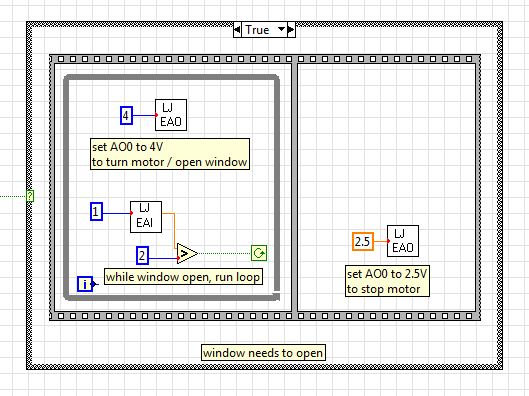
Gradual increase of the output voltage
I use EAnalogOut.vi from LabJack U12 for the U12 4 volts AO0 value. The instant change of output voltage is at the origin of the problems with the engine I use, so I ask: does anyone have an idea how I could program in the current diagram. To move gradually to 4 volts when first executed in the while loop and then little by little to down to 2.5 volts.
Instead of having a value of 4 GB in the analogue output VI, you must have your loop to change the value in small steps. Have a wait function in this loop. Use a shift register to feed into it and increment this registry to offset by small steps. Between the timer of the waiting and the number of steps and the size of the markets, you set will determine how long it takes to ramp to 4 volts. And of course more stages with smaller increments will be a smooth ramp.
-
Ghost NI USB DAQ card readings
Hello
I have a question about the behavior of the NI USB-6218 data acquisition card. Right now I use Labview to take several current readings of different channels to HAVE it. I use resistors 250 ohms for each channel just as the instructions say to make the current readings. I had an incident where he has been disconnected one end of a resistance at the entrance to the port. I expected to see the reading go to zero, but instead, he began to piggback off the coast of reading one another channel give me a kind of 'reading ghost' because there was essentially no current crosses. Playback of disconnected channel displayed the current reading of the canal connected even while values went upwards or downwards. Can someone explain why the DAQ card would do that? and anyway to avoid this to happen?
Thank you.
A data acquisition uses a multiplexer to send a signal to the ADC. Due to having only 1 ADC, you will get this effect if the ability has no way to bleed. There is no way to avoid this if you disconnect the side DAQ, leaving the open input channel.
You could try adding in some amplifiers specially designed for the shunts of currents. I have used TSC103IPTwith success. This amplifier gives you a single output is completed. But I don't know what will happen with these if you disconnect one side of the resistance of the amplifier.
-
Data acquisition in LabView for other suppliers DAQ cards that NEITHER
Hello
I am a beginner in LabView programming. I have a 32 channels base PCI card DAQ (i.e. PCI-1602 of the manufacturer, ICPDAS) and I want it to interface with Labview 8.5.
So how cards DAQ in Labview 8.5, which are manufactured by other suppliers that NEITHER? Should I DAQmx (or some other driver) for that?
What are the other drivers/components required to access of data PCI-1602 (device) of LabView 8.5 acquisition card?
(1602-PCI card driver are installed in my win XP and dispalyed in Device Manager).
Please provide some tutorial above mentioned the problem to interface.
Please guide me in this regard. Thank you
Waqar123 wrote:
Hello
I am a beginner in LabView programming. I have a 32 channels base PCI card DAQ (i.e. PCI-1602 of the manufacturer, ICPDAS) and I want it to interface with Labview 8.5.
So how cards DAQ in Labview 8.5, which are manufactured by other suppliers that NEITHER? Should I DAQmx (or some other driver) for that? You will need the drivers from the manufacturer, of the Board of Directors. In your case, "ICPDAS.
What are the other drivers/components required to access of data PCI-1602 (device) of LabView 8.5 acquisition card? Same as above.
(1602-PCI card driver are installed in my win XP and dispalyed in Device Manager). Ok. Then take you care of my 2 answers above.

Please provide some tutorial above mentioned the problem to interface. To learn more about LabVIEW, I suggest that you try to watch some of these tutorials.
Please guide me in this regard. Thank you
According to what you do with the DAQ cards, they can do the job however, from experience, there are some functions that I could achieve with the cards NOR that I couldn't with 3rd-party maufacturers. This does not mean that this is your case. However, it is worth noting that it took me a while to understand why the code has worked with a single data acquisition card (NOR) but not another (Non-OR).
The drivers that you have installed may or may not include examples and code in VI. They may be DLL. If this is the case, you can write LabVIEW "Wrappers" around these functions, as it will simplify your life. If the drivers are in the form of DLLs, and there are no examples of LabvIEW or available VI, you must read on node library function call.
R
-
What is the size of the sim card I put in an I Phone 6?
The SIM card provided by O2 for my new iPhone 6 more. has three sizes, nano, micro and standard. Which should I use?
The only one who would eventually be adapted, which is the Nano size sim card.
-
Channel of the DAQ (SMU-4498) task order
I have an SMU-4498 for which I generate an acquisiiton task programmatically. When the task is created channel order is not necessarily in ascending order of channel number.
My question is if the DAQ card will return the data in the order in which I defined the task or channel order?
Thank you
It seems that the answer is that channels must be specified in the order, when creating a task.
Maybe you are looking for
-
Open a pdf file - how can I avoid that Windows Media Player assuming the default
I download a PDF - and I want to store it in a file I left Adobe pdf, but I download and it is Windows Media player GUESS - it's a job for Windows - how to fix it-because Windows Media Player - is not all it is cracked up to for be and I want to sele
-
HP Pavilion TouchPad does not?
Hello, I have the HP Pavilion dm4 2015-dx and this morning when I started my computer the touchpad does not work. I use a mouse and it works fine however. I tried the download Synaptics and followed the instructions but it didn't work. Help!
-
I was remove some unnecessary programs and sudennly the computer ask me which program to use to open the other program. I turned off the computer and then I used safe mode to see if I could restore my computer to a quick setup. but the very thing. I
-
Hello Anyone know how to properly load images from a domain? I am trying to load an image from a domain, for example "http://domain.com/image.gif". When I try on the spot, it woks fine, but when I try to get a domain / server, it does not work. Here
-
Can we use JNI (Java Native Interface) approach in the Blackberry applications?
Hello Someone help me find if we use the JNI (Java Native Interface) approach in applications Blackberry JDE version 4, 5?