Channel of the DAQ (SMU-4498) task order
I have an SMU-4498 for which I generate an acquisiiton task programmatically. When the task is created channel order is not necessarily in ascending order of channel number.
My question is if the DAQ card will return the data in the order in which I defined the task or channel order?
Thank you
It seems that the answer is that channels must be specified in the order, when creating a task.
Tags: NI Hardware
Similar Questions
-
Possible reasons:
Scripture cannot be performed because the number of data channels does not match number of channels in the task.
When writing, provide data for all channels in the task. You can also change the task so that it contains the same number of channels as the written data.
Number of job channels: 8
Number of data channels: 1Lama says:
The DAQmx vi writing gives me the error. If I run a single channel, isn't a problem. Multichannel gives me error.
You are funny! Why tie yourself to work VI (single channel) instead of one that gives you errors (multichannel)?
(If your car does not work, you bring car your wives to the mechanic, right!)
What is the exact text in the multichannel 'physical channels' when you do the AO control?
Lama says:
I did a sequence to ensure that each function has been run in the correct order. Wouldn't a race condition.
All you have to do is wire the 'start of task' error at the entrance of error of the DAQ assistant and then back to 'stop task' and things will run in order. Guaranteed! Think the stream! Everything else can run in parallel or the order is irrelevant.
First convert the sequence stacked to a sequence of plate, remove the flat sequence and add the mentioned son. Now, do a "cleaning pattern.

A when stacked with the inhabitants of the sequence is one of the worst construction you can possibly do. It makes the code difficult to follow, impossible to maintain, difficult to debug.
-
Hi all
I am having some problems of data collection with a VI that I put together using LabVIEW 2010 and DAQmx 9.5. My DAQ hardware is an SMU-6341 in a chassis SMU-1071. I have a single VI which runs through all the tasks and controls that are channels in each task. Channels are then moved into a knot of channel property to check the type of channel. It allows me to adjust program which DAQmx read that I use to read data from the buffer.
I get error code-200428 stating that the task I'm passing in the channel property node is not valid. It then gives me the CHANNEL name that the task is not valid. Am I assuming I can switch from channel at the entrance to a property DAQmx node reference? I know that the task and the channel of the task are configured correctly because I can see the voltage on the digital output terminal.
Any help with this would be greatly appreciated.
Best regards
Ryan
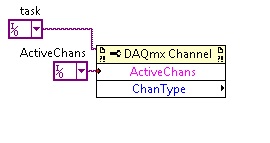
Types of channel properties are weird.
You must connect the task in the upper left entry of the channel property node, not the channel.
Then choose the 'Active channel' property and add another property to the node which is chanType. Son of your channel in the first and get the chantype of the second property.
-
Using the SMU-6368 module, I would like to monitor the analog signal on multiple channels and trigger on several channels - relaxation and acquisition channels is all on the same device. Probably going to be sampling at 200 kHz and more. FM LV 2009 2012, with SV toolkit in Windows 7.
If SW trigger is the only way to follow, there example code shows how to manage the block size, etc.. ?
jkessler,
Yes, the example was in 2012. I didn't get what you asked for in your first post because I didn't know you wanted to ANY channel to trigger acquisition of all channels. It is not possible at the hardware level, because you cannot specify four channels as the command source. This will be implemented in the software. I recommend the reading of all four channels and neglecting data until you determine that one of the channels reached your threshold value.
Kind regards
-
Set the scale of thermocouple at table for a channel in the task
I create a task that contains 9 measures voltage and 10 by thermocouple programmatically. All the thermocouples are of Type T. I just want to read one of the thermocouples up to the limit of 30 k. NOR for the Type T is 73 K.
I understand that the lira below their limit thermocouples OR is to change the scale type to table using a property DAQmx Channel node. However, because I take different types of measures, I need to isolate the channel particularly thermocouple. If I move the entire task to the node property DAQmx channel and try to set the scale of the type of thermocouple to table, I get an error because the voltage channels do not support this property. I can't understand how to get individually on channels of the task. I don't want to separate the measures into two tasks, because then I have to do to synchronize the clocks of additional programming.
I have more than one idea: use a DAQmx create task VI at the beginning. Do a global virtual channel to MAX for the thermocouple that I want to change the type of ladder for. Place a constant for this virtual channel and run through the DAQmx Channel property. Use the task of creating DAQmx to create a task containing this global virtual channel. Pass this task to a bunch of DAQmx create Virtual Channel screws to add other measures to the task.
This makes a lot of the scalability of my program and seems to be the wrong shape in general. Looks like there should be an easier way to do it. Any ideas? Thank you!
Hello
Try to use the property node of channel Active channels (ActiveChans) that is by specifying the string "isolated" as its input, and then adding the (HAVE. Themcpl.ScaleType) in developing the property node even by setting its entry. The property node Active channels specifies a list of virtual to change channels or virtual channel. Virtual channels are in a specific job. NOR-DAQmx configure all channels in the task if you do not set this property

Best regards
M Ali
Technical sales engineer
National Instruments
-
Hello
I'm writing analogues of the buffer to several channels using NOR-6723.
For some reason any, whenever I go to the buffer double function (1-d) that contains buffers for all channels.
I always find myself with exception indicating that the numbers of channels in the data are '1 '.
I use c#:
Task m_TaskHandle = new Task();

string sChannelsList = "Dev2/ao21:23";

m_TaskHandle.AOChannels.CreateVoltageChannel(

sChannelsList,

"", 0, 5, AOVoltageUnits.Volts );

int iNumberOfSamples = 4;

double dSamplingFrequency = 1000;

m_TaskHandle.Timing.ConfigureSampleClock("",

dSamplingFrequency,

SampleClockActiveEdge.Rising,

SampleQuantityMode.ContinuousSamples,

iNumberOfSamples /* Only relevant if mode is FiniteSamples */);

// Data code is heredouble[] adSampleBuffer;// array values removed from this code snippet (here i have function that generates data)// array size is: num_of_samples * total_channels (in this case 4 * 3)

AnalogSingleChannelWriter ChanWriter = new AnalogSingleChannelWriter(m_TaskHandle.Stream);

ChanWriter.WriteMultiSample(false, adSampleBuffer);

m_TaskHandle.Start();
Not sure I'm I missing, how the MSTDIO determines the "number of data channels", I receive as an exception, it is always equal to 1.
would appricate to help.
Thank you.
Hi idanbis,
As the snippet you posted, you can create more than one channel using the ao21:23 range. That said, you should use AnalogMultiChannelWriter to configure your write instead of AnalogSingleChannelWriter operation.
To write using AnalogMultiChannelWriter::WriteMultiSample (boolean, double, you must know the data you want to write must be stored in a 2D array.) Each element in the first dimension of the array corresponds to a channel in the task, while each item in the second dimension, to a sample of write on its channel. For example, that:
Double [,] data = new double [numChannels, numSamplesPerChannel];
Then:
data [0, 0... numSamplesPerChannel]; It is the set of all samples in the first string (ao21 in your code).
I hope that was helpful. Let me know if I left any doubt remaining.
Best regards
Anzurio
-
I have a DAQ Assistant configured to read 2 channels at the same time. When I have a graphical indicator of wire to the output, I see 2 signals mixed together. How I divided them into separate signals?
When I wire any type of indicator, it is show that a release of a single channel.
I want 2 indicators showing 2 different signals as expected from 2 channels configured. How to do this?
I tried to use split signal but it end by showing that 1 out of 1 signal two indicators.
Thanks in advance.
Yes you are right. I tried, but I don't have the result.
I just find the path. When we launch the split signal, we should expand it (split signal icon) by top, not the bottom. It took me a while to understand this.
Thank you
-
Relaxation in beginning digital DAQ - shows on 4 channels for the digital dashboard start
Hello
I start my DAQmx task with a trigger on a rising digital. It works fine, but I have to look on 4 channels, not only on one.
So if I get a digital camera on any of these 4 channels of my task DAQmx should start.
How can I modify the beginning of trigger DAQmx standard to include 4-channel - monitor for digital advantage start task connected?
Thank you.
Unfortunately, it is not currently possible to use several lines like triggers. Change detection approach will be the best approximation for this. Another option, assuming that you don't mind a small amount of external circuits, would be to use a door or external to your block of endings that SOR four external lines and routes the result to a trigger line. It would probably be the simplest solution, as OR doors are relatively cheap and would not require a change in software.
Kind regards
-
Error-200478 - specified operation cannot be performed when there is no channels in the task
I write a task in NiDaqmx read 8 thermocouples 2 9222 or 4 thermocouples of a NI 9223 modules. Under Source of CCM I entered the channel and specified a type K thermocouple connected to a NI 9219. All modules are located in the same chassis of cDAQ9178.
I get the above error.
I add the CJC channel and he complains that I have double readings of the same channel in one of the tasks.
The environment where it will be installed will vary widely affecting thus the constant CCM is not a viable option.
Any help would be appreciated.
Simple reason - we already possess the 9222 s of NOR and the NI 9223. I'll check the price NI9213 and see if the Group has the budget.
I watched your program and compared it with mine. Tried to channel the CJC as Temperature_12 but all local channels are grayed out. BUT I moved Temperature_12 the command to the top you and Voila! He is available for selection. I put all 9222 s and 9223 channels at points to Temperature_12, and it saved without error.
So I would say put the CJC channel as the first channel to read fixes the problem - it makes sense that the following channels need a reading to serve their CCM. Where this logic breaks down is if you consider that the 9222 and 9223 channels are simultaneous channels, but that's a topic for another post!
For now, I thank very you much for your help.
Best regards
Dean
-
DAQ Assistant do not find channels of the cDAQ
We recently bought the Compact DAQ and two thermocouple modules 16 channels. I am trying to change a code to use a Pico USB logger for the cDAQ and I'm trying to follow the examples found on your Web site using the DAQ Assistant. Initializes the DAQ Assistant, and I choose analog input for the selection of Signal acquisition. When I select the option of Thermocouple temperature section, it says "reading of Lecture de Configuration Configuration of the system, please wait...". "but it never picks the cDAQ channels. I installed drivers and recoginizes of the USB port on the device (and the light indicates that it is in "ready" mode), but it has never been "Reading System Configuration."
Thank you for your time.
Solution has been found. It turns out that the data folder was corrupted files it contains. Once that I deleted it MAX started to work very well.
-
order a fan with USB6251 and the Daq signal accessory
Hello
I have a school using Labview project and the USB6251 connected to the Daq signal accessory card.
The Labview program must read continuous temperature (Ia 4 channel, internally) temperature probe connected to the accessory of Daq Board signals. When the temperature reaches an established value, then a led on the front panel should be lit and a singal output data acquisition should start a fan connected to the acquisition of data which cools down the sensor, then stops.
Would it not be possible to do something like that? Even if I generate a square signal and the fan only works on the State of the signal. The fan requires at least 120 mV DC current. I'm afraid that if I take these courses for the acquisition of data, I could damage the unit.
Thank you.
I guess you mean 120 current my DC
. If you look at your spec of daq card, you will find that the current max are far below 120 my. This applies to the two analog out and digital out. Take a look at this site, it may be useful to some. site nice http://www.me.umn.edu/courses/me2011/robot/TechNotes/motorcontrol/motorcontrol.html . If you want the speed controller, you have two options PWM or voltage of the motor regulation.Good luck
-
How to create a task in the DAQ Assistant of LabView for one of our modules cDAQ without actually being connected to the cDAQ module?
You can simulate a large number of instrument supported by DAQmx with Measurement & Automation Explorer.
Right-click on the NOR-DAQmx devices and then create new, then simulate and choose from the list of supported devices.
For the cDAQ chassis first then your module.
Excuse me, but I don't have an English version of MAX and so I did not have the correct translation of command...
When your simulated device is configured, ca use you it with the DAQ Assistant in LabVIEW.
-
Precise triggering voltage input and output generation in the DAQ Assistant
Hello
I wonder if anyone has come across a simular problem with the synchronization of input and output voltage. I use a box 11 LabView and NI USB-6259. I have been using the DAQ Assistant to configure the input and output channel. In particular, my task is to generate a single rectangular "pulse" as the output voltage to drive a coil and once the pulse went to get a signal from a sensor of magnetic field and get a power spectrum. This means that the order and the time during which the DAQ Assistant is used is extremely important. For example, the output voltage channel must be opened first for 2 seconds. Subsequently, the channel of input voltage must be open for 1 second, in which the sensor signal is obtained and post-processed. Only after these tasks are performed in this order he can can be repeated in a loop until the experiment is over. I don't know how to trigger data acquisition assistants (one for entry) and the other for the voltage output correctly. Y at - it a trick?
See you soon
Michael
Hi Dave,.
Thank you that I wired the error strings but the timing issue was unrelated to it. In the DAQ assistant, I simply had to choose the continuous aquistion of the 'samples' methods 'N-switch' for input and output voltage and all works fine now.
Thanks again
Michael
-
Dear community,
I am trying to implement a background basket (software) PXI trigger on a chassis NI SMU-1082 with LabView 2015 (32-bit) running on an SMU-8135:
HS-DIO (SMU-6544) in slot 2,
-Acquisition of data (SMU-6363) into the Groove 4,
-Flex RIO (SMU-7962R + OR-6583) in the Groove 3.
The trigger schema is explained in the attached file ' LV-PXItrig-HSDIO-DAQ - overview.jpg ".
Scenario 1: written DAQ analog signal and sends signals trigger HS-DIO (software) through bottom of basket, after East of waveform of the complete signals to DAQ for acquisition.
Scenario 2: logical impulse on an external port HS-DIO triggers signals HS-DIO, after HS-DIO waveform is complete DAQ triggered for the acquisition of the ADC by the backplane.
In principle this breaks down to send a trigger of module A to B by PXI backplane. The SMU-1082 chassis has a bus trip with 8 lines (PXI_trigX, X = 0,..., 7) more a trigger in Star controlled the slot 2.
I've linked to implement a software trigger, but I can't access the refreshing resource and execution, see the attachment. Other ways of implementation including the DAQmx Terminal / routine disconnect Terminal have not worked for me either. I am aware about the connection of trigger using the node property VISA but I can't make a trigger.
Tips, comments or solutions are appreciated. Thank you!
For scenario 1, you want to trigger the HSDIO acquisition to begin as soon as the analog output DAQ starts? You can use
DAQmx Export Signalto send the trigger for the start of one of the lines from the Trig PXI backplane. Then, you need to configure your HSDIO acquisition to use a trigger digital beginning on the same line of trigger. Take a look at the example of the "Dynamic hardware generation start trigger" in the Finder of the example (help > find examples)For scenario 2, looks like you do a dynamic unit HSDIO generation when a digital trigger arrives on one of the PFI lines. Once the build is complete, you want to send a trigger for the DAQ hardware to begin sampling. If this is the case, you again use a trigger to start material in your task of NOR-HSDIO, as you did for scenario 1, but use external trig line as the source, rather than the bottom of basket. There is no case of material when the build is finished, but you can use a marker in script mode event instead. The example of the Generation with dynamic event marker' in the example Finder gives a good starting point for this type of operation. You'll want to set the output terminal for the event to be a line of backplane trig, and then tap the DAQmx to start on the same line trig trigger.
-
samples per channel and the number of samples per channel
in my DAQ mode samples finished program, there are two screws: timing and read.vi DAQmx DAQmx.
I have to set the parameter to "samples per channel" DAQmx timing.vi and 'number of samples per channel' on DAQmx read.vi... Is there a relationship between these two?
My laser runs at 1 K Hz. I want to go to the wavelength, wait for a number of shooting lasers, read the data and move on to the next page...
Thank you
Lei
In your case, the VI will acquire the lesser of either:
The "samples per channel" that you have defined on the timing DAQmx VI
-OR-
The number of iterations of your for loop (N) times the 'number of samples per channel"that you have defined on the DAQmx read VI
The "samples per Channel" VI DAQmx of timing for a finite acquisition dictates how many samples the DAQ hardware should acquire in it's onboard buffer before indicating that the acquisition is complete. "The number of samples per Channel" on the read DAQmx VI dictates how many samples the DAQmx driver must return buffer on board the aircraft to your application.
Let's say the "samples per channel" on the calendar DAQmx VI is set to 50. Thus, the card will acquire 50 samples and place them in the edge of the buffer, then stops. Suppose we have the 'number of samples per Channel"on the DAQmx reading VI the value 3 and what we call the VI in a loop For which runs 10 times. Thus, every time the DAQmx lu VI is called, it will wait until there are at least 3 samples in the buffer, and then return these three. We call the VI a total of 10 times, then we will answer 30 total samples. Thus, the last 20 samples acquired the card remains in the buffer and are destroyed when the task is disabled.
Now let's say that we increase the "number of samples per Channel" on our DAQmx Read VI at 10. VI Read will wait until 10 or more samples are in the buffer, and then return these 10. Thus, we will be back all 50 samples map acquired by the 5th iteration of the loop For. The 6th time we call him VI DAQmx Read it expires, because there will never be another 10 samples in the buffer, and the VI returns a warning.
This clarifies things?
The purpose of this behavior is to allow you to both set the total number of samples that the DAQ hardware will acquire and also control how much of these samples is returned whenever you call the DAQmx Read VI.
Kind regards
Maybe you are looking for
-
Server does not recognize my user name on outgoing emails
On my iPhone 4 my server does not recognize my email (Telstra) address on outgoing emails, but recognizes the incoming emails. What happened all of a sudden no reason apparent. I have two other email addresses on the phone and they work fine. One is
-
Demon of launch system: com.apple.devicemanager.plist - no signature!
MacPro 1.1 Quad 16 GB memory Boot SSD 10.7.5 system No crashes Someone has an idea of what to do about the line of just report below EtreCheck: Launch system demons: (Does that mean?) [loading] com.apple.devicemanager.plist -no signature!
-
Support for customization of the graphical appearance
I try to have a nice enough xy graph for an article. What I did (hoping that you will understand me) is to remove the black inside the plot and the gray in the outer region by using the tools palette choose the fg and the background color as transpar
-
music msn my computer certificate is expired or invalid.
I managed to transfer my music files purchased from my old computer to a a flash and then drive to my new computer, but I am currently having problems authorizing my music files on it. I think the problem is that the music from my computer certificat
-
Networking Windows 7 with XP using the router and no internet - machines cannot be
Hello I searched the web and tried all kinds of suggestions to do this, but my new Win7 machine does not always show my daughters XP machine, and vice versa his XP machine is not showing my win7. I don't want to have access to the internet so current