Outputs digital synchronized DAQmx
Hey, I am trying to send two synchronized digital signals of a PCIe-6420 device.
Here is my code:
DAQmx configure clock
DAQmxErrChk (DAQmxCreateTask ("Clk", & taskHandleFRQ));
DAQmxErrChk (DAQmxCreateCOPulseChanFreq(taskHandleFRQ,"Dev1/freqout","",DAQmx_Val_Hz,DAQmx_Val_Low,0,ManchSampClkFreq,0.5));
DAQmx digital output configuration
DAQmxErrChk (DAQmxCreateTask ("Harmony", & taskHandleHarmony));
DAQmxErrChk (DAQmxCreateDOChan(taskHandleHarmony,channel2,"",DAQmx_Val_ChanPerLine));
DAQmxErrChk (DAQmxCfgSampClkTiming(taskHandleHarmony,"/Dev1/PFI14",ManchSampClkFreq,DAQmx_Val_Rising,DAQmx_Val_ContSamps,sendCount));
DAQmxErrChk (DAQmxCreateTask ("DOchan", & taskHandle));
DAQmxErrChk (DAQmxCreateDOChan(taskHandle,channel,"",DAQmx_Val_ChanPerLine));
DAQmxErrChk (DAQmxCfgSampClkTiming(taskHandle,"/Dev1/PFI14",ManchSampClkFreq,DAQmx_Val_Rising,DAQmx_Val_ContSamps,sendCount));
DAQmx Configure similar output
DAQmxErrChk (DAQmxCreateTask ("AOchan", & taskHandle));
DAQmxErrChk (DAQmxCreateAOVoltageChan(taskHandle,channel,"",0.0,10.0,DAQmx_Val_Volts,));
DAQmxErrChk (DAQmxCfgSampClkTiming(taskHandle,"/Dev1/PFI14",ManchSampClkFreq,DAQmx_Val_Rising,DAQmx_Val_ContSamps,sendCount));
DAQmx write code
DAQmxErrChk (DAQmxWriteDigitalLines(taskHandleHarmony,sendCount,0,10,DAQmx_Val_GroupByChannel,SendManchHarmony,,));
DAQmxErrChk (DAQmxWriteDigitalLines(taskHandle,sendCount,0,10,DAQmx_Val_GroupByChannel,SendManchData,,));
DAQmxErrChk (DAQmxWriteAnalogF64(taskHandle,sendCount,0,10.0,DAQmx_Val_GroupByChannel,SendManchAnalog,,));
Starting code DAQmx
DAQmxErrChk (DAQmxStartTask (taskHandleHarmony));
DAQmxErrChk (DAQmxStartTask (taskHandleFRQ));
DAQmxErrChk (DAQmxStartTask (taskHandle));
Only problem, is that I get "error DAQmx: NI service platform: the specified resource is reserved." messages.
The name of the task associated with the error is DOchan: aka: taskHandle. If I rearrange the code such as taskHandler events occure before the equivelents to taskHandlerHarmony, then errors are associated with harmony: aka taskHandleHarmony instead.
That I am I doing wrong and how should outputs digital syncornized be implimented instead?
Think of the fifo in a block of memory that is the same width as the digital port where each bit corresponds to a single digital line. The samples are transferred from this FIFO to the port in written all over port (there is some logical activation, so only those lines that are configured in your output task are actually updated each sample clock). DAQmx will combine the data you write for if make sure that the correct data at the scale of the port gets written in the FIFO. DAQmx for this by looking at the configuration of the group 'line' in DAQmx create DO canal and the "dataLayout" specified for the function DAQmxWriteDigitalLines.
You have two lines you have set on DAQmx_Val_ChanPerLine. This means that when you call DAQmxWriteDigitalLines, it will be expected to see enough data to two data channels. The way in which these data are specified is configured by the dataLayout. By specifying DAQmx_Val_GroupByChannel, you say DAQmx data for each channel to be grouped. You should do these groupings in the same order that you specify your channels.
So consider the following:
DAQmxErrChk (DAQmxCreateTask ("DOTask", & taskHandleDOTask));
DAQmxErrChk (DAQmxCreateDOChan (taskHandleDOTask, "Dev1/port0/$line0", "", DAQmx_Val_ChanPerLine));
DAQmxErrChk (DAQmxCreateDOChan (taskHandleDOTask, "line1/port0/Dev1", "", DAQmx_Val_ChanPerLine));
DAQmxErrChk (DAQmxCfgSampClkTiming(taskHandleDOTask,"/Dev1/PFI14",ManchSampClkFreq,DAQmx_Val_Rising,DAQmx_Val_ContSamps,sendCount));
We will alternate digital high/low between our two lines (we will write the 10 values of each line), with the exception of this last point, where we will write two lines high
The data should be written in the corresponding line bit position (if I remember correctly)
which means you want to manipulate the lsb for the 0 line, and line 1 manipulate you the 2nd lsb.
Int32 [10] line0Data = {1,0,1,0,1,0,1,0,1,1}
Int32 [10] line1Data = {0,2,0,2,0,2,0,2,0,2}
Int32 dataArrayByChannel [20];
Int32 dataArrayInterleaved [20];
for (int32 i = 0; i)< 10;="">
{
Group data through
dataArrayByChannel [i] = line0Data [i];
dataArrayByChanne [i + 10] = line1Data [i];
Group the data by scanning
dataArrayInterleaved [i * 2] = line0Data [i];
dataArrayInterleaved [i * 2 + 1] = line1Data [i];
}
We can write data in one of the formats that we just built, but we must provide DAQmx with the correct dataLayout.
DAQmxErrChk (DAQmxWriteDigitalU32 (taskHandleDOTask, sendCount, 0, 10, DAQmx_Val_GroupByScanNumber, dataArrayInterleaved, NULL, NULL));
Alternatively, we could write per channel. If we chose, it would look like this (you wouldn't do both).
DAQmxErrChk (DAQmxWriteDigitalU32 (taskHandleDOTask, sendCount, 0, 10, DAQmx_Val_GroupByChannel, dataArrayByChannel, NULL, NULL));
DAQmxErrChk (DAQmxStartTask (taskHandleDOTask));
In both cases, DAQmx must write the following data to the FIFO:
x 1
x 2
x 1
x 2
x 1
x 2
x 1
x 2
x 1
x 3
In this way, the data written to each line are combined by DAQmx then written to the FIFO. Allows you to specify the data for each channel individually.
It was quite long, but I hope it will answer your question. If I was not clear, please let me know.
Dan
Tags: NI Hardware
Similar Questions
-
Back table of outputs digital for all available hardware
Hi, I use an output digital on the USB-6008 box to toggle a switch to relay. The problem is that the State is initialized from the all the outputs for this device is high when the unit is first powered. So, I include in my code to set the digital line (saved in the config file) solenoid low when the program first runs. The real problem is that the first time that the program works on other computers, depending on the hardware installed, the line can have a different name.
Is there a way to return an array of all available digital output lines, so that I can put all weak when my program works first? One of these lines will be the one I really want to put down.
Thank you
Greg
Dig in the DAQmx palletes for nodes and constants to find a node 'system '. Select the "DevNames.
Wire as arry in a loop with a node For "Device" and you can choose the "product Type" or "product number".
Ben
-
6009 outputs digital and analog input synchronization
Hello
I work in a program NI 6009. I want to leds by car with outputs digital NI 6009. For example, leads first will be on until what 200 micro seconds then second led will be on up to 200 micro seconds, and then first of all led will be on up to 200 micro seconds. I'll take led with photodedector signals and connect analog output photodedector input NI 6009. I want to synchronize the outputs digital and analog input and separate the first and second led signals the analog input for NI 6009 channel. How can you do with NI 6009? Please ADV
You can not do with the USB-6009 case. Its outputs digital are software with a maximum speed of slightly more than 100 samples per second. The outputs can produce 200 microsecond pulses and cannot be synchronized with the analog input.
You need a device with outputs digital hardware timed or counters that can produce a pulse outputs.
You can synchronize a bit digital output and analog input recording signal on an additional channel to HAVE. Will allow you to see the photodetector and LED the drive with the same schedule and such resolution as described by the sampling rate I. The maximum sampling frequency of AI on the USB-6009 case is 48 kHz that is shared by all channels. If you have two lights to led and photodetector two signals maximum sampling rate would be 48 kHz/4 = 6 kHz which is barely fast enough for your 200 US signals. For more than 4 channels, it won't be fast enough.
I suggest a simple oscillator circuit building and use it to clock a flip flop. This will give you alternating signals to drive the LEDs. You can use a line to reset the flip flop to give you control without the need for high speed.
Lynn
-
Current output digital USB-6009
Hi, I'm trying to increase the voltage output digital device USB-6009. I read a few topics on the use of a relay, but I couldn't get it.
I was thinking of using power 5V on the map because there current 200mA on it, but when I use it with open-collector output, it cannot change the relay. When I measure the current between
5V and ground: 200 ma,
5V output, I read a value around 30-40 my.
Why can I not use this 200mA with output? It is the Relay that I use.
If this is not possible, can I use an external power supply 5V (with more current) and a digital output to pass the baton without damage the 6009?
Outputs digital of the USB-6009 confined to 8.5 my. Your relay coli requires much more than that. Even if the power source can provide enough current for the relay, digital output can not put.
The solution is to use a buffer of extermal. The ULN2003 can switch currents up to 500 my and voltage up to 50 V while being controlled by digital output.
Lynn
-
output digital 1 sec ON - 9 OFF s
Hello friends,
I'm new to LabView.
And I'm working on a project where I have to order 6 relays via lines outputs digital data acquisition in question. (USB-6353)
Each relay is ONE for dry and OFF 1 for 9 seconds. But they all should be out of phase. If only 1 relay is active at a time.
Can someone help me with this in Labview.
Thank you.
-
Audio output digital on Lenovo docking station and Port Replicator
Dear community,
There is no station Lenovo port replicator or docking station for Thinkpad recent (T440 & X 440) with audio output digital?
A big thank you in advance?
Amine
Neither has it. You need something like that. It divides basically your audio digital HDMI or DP.
http://www.envioustechnology.com.au/products/images/further/HDMI-SW41_Inline_01.jpg
-
DAQmx: Outputs digital multiple tasks for the same card using the on-board clock
I have a PCI - 6259 DAQ I'm programming with DAQmx. I want to create two tasks of digital output on the same card. A single task using on-board clock, continuous samples. The other task uses an onboard clock, finished samples and an external trigger with trigger Start.Retriggerable property = TRUE. Is this possible with my hardware and DAQmx? There will be a conflict if two tasks use the same clock source?
This is not possible, you can have only one task timed materially by device.
Best regards
-
9401 buffered output digital clock sample source
Hi, I would like to generate a pulse train with a defined number of pulses, according to a defined periodicity. I use a NI9401 module in the Groove 3 CompactDAQ chassis so that I can write the required buffer sample 2047 pulse train. The problem I have is I am unable to choose any clock source slower than the time base of 100 kHz, which means that the buffer can underflow very easily. I would use a 4 kHz clock source, but cannot find how do. If I want to generate a source of the clock of one of the counters, I must have the 9401 in slots 6 or 7 which then do not allow for generation of digital signals in the buffer...
Hi, JPP,.
Access to internal counters, even if modules are connected in the Groove 1-4 of the cDAQ chassis. Note this site 6 & 7 are necessary only if you need external access to counters as task of counter in the buffer, the measures of frequency/period, etc... Since in your application, all you need is to generate a continuous pulse train and access its output internally to clock output your digital correlated, this shouldn't be a problem with your DIO module into the Groove 4. Please take a look at the following link for more information.
With the help of internal counters on one NOR cDAQ-9172 as a sample for other tasks clock
http://digital.NI.com/public.nsf/allkb/EEB574335BA0B4EB862572060055E9DD?OpenDocument
I would also like to refer to an example on our site which shows you how to use your correlated digital i/o clock counter. I hope this helps.
NOR-DAQmx: Digital Correlation of e/s with NI CompactDAQ and LabVIEW
-
analog output digital start trigger the api c
Hi, I'm trying to start analogue output based on a digital trigger (either PFIO or a PXI line) I can make this easy in LabVIEW. However with the C API (through the Python wrappers), the problem is when I call DAQmxBaseWriteAnalogF64, writing will always be timeout that the acquisition was not triggered. However, I can't call it after the trigger occurs, because obviously, it will be too late.
I can't find any examples of C API where the analog output is triggered a digital triggering. I can find for the analog input, but is fundamentally different that you can CONV read anytime after the trigger occurs.
Python code as follows (functions are equivalent ot C API, even if you have no need of ot pass the task handle such that it maintained as part of the Task object)
# create analog output task
analog_output = Task()
analog_output.CreateAOVoltageChan("Dev1/ao0","",-10.0,10.0, DAQmx_Val_Volts, None)
analog_output.CfgSampClkTiming("",outputRate, DAQmx_Val_Rising, DAQmx_Val_FiniteSamps, numSamples)
analog_output.CfgDigEdgeStartTrig("/Dev1/PFI0", DAQmx_Val_Rising)
analog_output.StartTask()
analog_output.WriteAnalogF64(numSampsPerChan=numSamples, autoStart=False,timeout=1.0, dataLayout=DAQmx_Val_GroupByChannel, writeArray=data, reserved=None, sampsPerChanWritten=byref(samplesWritten))print("Analog output: Wrote %d samples" % samplesWritten.value)# create digital trigger dig_out = Task()dig_out.CreateDOChan("Dev1/port0", "", DAQmx_Val_ChanForAllLines)

# create digital trigger function
highSamples = 1000
numpts = 3 * highSamples
doData = np.zeros((numpts,), dtype=np.uint32)
doData[highSamples:2*highSamples] =  2**32 - 1

# send digital trigger
doSamplesWritten = c_int32()
dig_out.WriteDigitalU32(numSampsPerChan=numpts, autoStart=True, timeout=1.0, dataLayout=DAQmx_Val_GroupByChannel, writeArray=doData, reserved=None, sampsPerChanWritten=byref(doSamplesWritten))
print("Digital output: Wrote %d samples" % doSamplesWritten.value)
Hi PatrickR,
You can review examples of code NI-DAQmx (ANSI C) text based on the production of an output using a trigger to start digital analog. If you included/checked support textual dusing your NI DAQmx driver installation, you can navigate to Windows start > all programs > National Instruments > NI DAQ > Teaxt-Based Code support > ANSI C examples > analog output > generate voltage > Mult Volt updates-Int Clk - Dig start. If you have questions/doubts about the material.
-
Hello
This should be very easy, but for some reason, I'm going to have questions. All I want to do has a switch control a digital output. I use a card NI 9742 Dsub (link), which should be capable of digital output.
My code, with a simulated map is attached. During the test I change the properties of the real card DAQ assistant.
Using this code, I can't get a DC output at all, my scope is all about 100mV. Using other cards, I have the analog i/o works fine, but for some reason, the digital output on this card isn't? In addition, if you look at the map, there are 8 green LEDs upward. I think that each specifies when an output should be enabled. When I turn on the switch, the corresponding led lights actually, but I can't measure a voltage? Is there a setting I'm missing?
I hope that makes sense. Thank you!
-secondary question: once it works, how can I change the output range. The specs say output 6V - 30V, but I do not see where to change that.
g e m e n i,
I looked at your code and noticed that it includes only a DAQ Assistant and a Boolean matrix of values to write.As it is currently, the VI will be only write a single value and then stop. In order to write constantly, you will need to place your code in a While loop.
If you see still no signal the evolution of 9742, consider opening one of the expedition DAQmx examples. You can find these examples in LabVIEW by going to help > find examples...
Try the following example: material input and output > DAQmx > digital generation > write hollow Chan.vi
-
Friends,
I need help with the following situation: I want to trigger a digital output of Myrio with just a single pulse, and after this impulse, the digital output must remain enabled.
Then with another single pulse, the output should be turned off
Anyone know how to make a similar request?
Thank you for the opportunity
Best regards
Q.Silva
Hi Silva05,
I did a little research for you answer and I found another "NI Discussion forums" forum that maybe can help you.
Try using this link, I think this will help you.http://forums.NI.com/T5/academic-hardware-products-Elvis/myRIO-digital-trigger/TD-p/3278560
Best regards
-
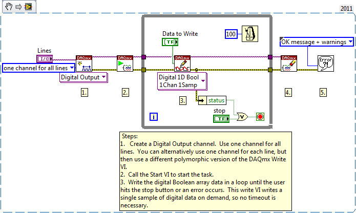
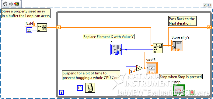
Storage of the outputs digital of an element in a table 1 d
Hi all
It must be simple and easy, but I don't seem to get it. A sample VI is attached.
I have a slider control which I do a manipulation to generate an output of the digital item. I can keep on sliding and get that the output generated, but now I need to store all the possible exits in a 1 d table.
Your help will be very appreciated.
Concerning
Yes quite simple and easy. You missed a few basics about LabVIEW. See the note to the modified VI.
(Also presented as snippette for those who don't mind the commitment of the DL
-
Maximum frequency of outputs digital
Hello
I use a NI USB 6218 BNC camera. I try to turn on/off the digital IOs hoping to get a frequency of 1 MHz. However I'm unable to get more than 600 Hz. Should it? Is there a way to get a faster frequency? I tried programming in LabVIEW and C++ (both in Windows 8), but it has not really helped.
My goal is to use three outputs as controlled clocks, which must run on demand with a specified number of cycles and, with a phase shift. Is there a way to do this with this camera?
Thank you
Ravi
The specs say it's a programmed software. You can write a sample at a time. MAX speed depends on the os bit usually tops out at 1 kHz about. You do not have two counters, but you will need a different material at the exit of the three clocks.
-
I inherited a data USB-6343 acquisition unit and tests a few pieces I designed. The latest version of the chip has 3.3V / s and it appears that the 6343 only supports digital i/o to 5V. Is there a quick way to convert the output data acquisition in 3.3V 5V? Thank you.
Hello
I thought it might be useful to display some of these to the top on the same topic:
I understand you are trying to run the code example "Static digital output with adjustable logic level. When you set the level to 3.3V logic you see an error message.
Here is an article on knowledge (KB) which explains what this message means. In this KB is now talking of another property, but the concept is still the same.
http://digital.NI.com/public.nsf/allkb/05A563FE3AA7B3C286256FF90077C303?OpenDocumentI also did a little more research and found this useful reference which caught shows supported properties for the device, and you can see that this property is not supported.
http://zone.NI.com/reference/en-XX/help/370471Y-01/cdaqmxsupp/USB-6343/In conclusion, you are limited to the 5v output only if you need to obtain 3v to drive your relay maybe I could suggest that you use a converter logic circuit that converts your 5v with 3.3V.
I hope this information helps.
Let me know how you go.
Kind regards
Kevin Ross
National Instruments
Engineering applications
www.NI.com/support -
Output digital NI 6224, acting abnormal when the PC off.
Dear all,
I use NI 6224 to control cylinders, light turn and etc.
Just output port Act abnormal during PC power off, and it return to its original position, which he assumed to be when PC power on.
Is where all the parameters available in MAX be able to solve this problem?
Thank you.
Anson,
The PCI card is powered by the PC. When the PC is turned off, the card has no power. Without power, it is in an undefined state. Most likely, it presents an impedance moderately high what whether at its release. If external devices by default entries = high when not actively pulled low (which is the case for the TTL), then the power off of the State of the 6224 may resemble high logic for external devices.
There is no way that the PCI-6224 (or any other logic device standard) can control his outputs when it has no power.
If these devices may still have power when the computer is turned off, then you need to add a couple of circuits integrated between exit security digital and external devices. The details depend on what these devices require, how fast you need to disconnect and other factors.
Lynn
Maybe you are looking for
-
10.1.2 iMovie crashes on startup with error log Codec32BitTool
iMovie 10.1.2 on El Capitan crashed shortly after the start - I can get it to display the welcome message - and there are two diagnostic reports of the user in the Console. The corresponding message is displayed as follows: Codec32BitTool_sb_2016...
-
Firefox displays the weird texts
I use Firefox 32.0.3 on my Windows 8 (. 1) PC. The problem I've always faced with Firefox on my Windows 8.1 machine is that Firefox displays the text incorrectly, see screenshots here: http://1drv.ms/1xCwgJ0. It happens more often in Favorites, menu,
-
your view all the history button is FANTASTIC... however... there at - it an option or feature where I don't see only when I last visited this site path on my pc, but also the length of time I've spent on this site or the path?
-
More OfficeJet Pro 8600: picture difficulty of paper in the tray
For the first time, I am trying to print a photo of my MacBook Pro/iPhoto with photo paper glossy premium, brilliant. The printer has difficulties to enter/loading paper. I had to gently push the paper the printer to enter and print the photo. The
-
How to connect a MacPro to a TV with S connector or banana plugs
I have a MacPro bought in 2013 and want to connect it to an older flat screen TV. The TV has a connection port "S". It also has a yellow, white and Red connection port. Is there a configuration of connection cable I can use to achieve this? Apple sup