Question of Timestamp of average output DC - RMS.vi
I'm having a problem with the timestamps on the output waveform RMS value of the DC - RMS VI on average. For some reason, it is as if the time will speed almost triple! This can be seen in a graph shaped wave, as well as when data is stored in a file. When the VI of DC - RMS average is removed the timestamps back to the correct speed.
See the timestamps in the lower right data attached maps. The plot at the top of the page uses the VI DC - RMS average is not the case of the background plot. Both ran for the same amount of time, but as you can see the upper trace got about 18 seconds before the background plot.
You need to reset your average with each iteration. I'll be honest, I don't know exactly why you need to do this, but it solves the problem and you get a beautiful curve of RMS who remains with the timestamps of the RAW files.

Edit: It seems that something weird happens with the value of t0 after VI RMS does its thing. The t0 of the waveform of the RMS is to jump before t0 of the raw data of 0.08 seconds each iteration. It should be always 0.08 sec higher, but for some reason it is additive without resetting the filter.
Edit2: You also get a corresponding timestamp if you change the type of averaging exponential instead of linear default value. The curve is slightly different but because you now get an average including the previous data, not only the most recent points being on average.
Tags: NI Software
Similar Questions
-
Questions about the synchronization between output and analog input
Hi all
I now have a simple task which head a signal voltage (from PXI ao0) on a circuit and then your comments a voltage at the terminals of a component, for example, that one of the resistors in the circuit, through ai0 on PXI. So in this case, the synchronization between analog input and analog output must be made to avoid error of phase shift.
I tried to build my VI by learning this example: https://decibel.ni.com/content/docs/DOC-3882
However I have a few questions.
1. I noticed that there is a merged error fed the "start task" sub VI for the analog output. What is the point of fusion to mistake?
2. I enclose my VI (also shown below) for the output voltage. I put my writing of DAQmx Subvi in the while loop so that I can change the voltage while the VI is running.
However, in the example, the author has been reading outside of the loop and before even the start task. What difference will it make?
3. I have also attached my synchronized VI. I always put the wavegeneration and the DAQmxwrite in the loop. A bulging guard error saying about samples is not available and needs to a higher sampling rate or a longer wait time. What causes this?
I appreciate that these problems can be solved. Thanks to you all.
(1) first you need start the task of acquiring, he'll wait for trigger here. And then you start the build task that provides this trigger. If acquisition could trigger and never start.
(3) you must first write something in the buffer (writing DAQmx), then only you can generate it (Daqmx Start).
Check Cont Gen tension Wfm - Int Clk - no Regeneration.vi in the help-> examples for example.
-
Question about "Menory use (average)"... in graphic
Hello.
Please, I have a basic question... Please, see the picture I have attached, consider with the virtual Center...
Grafica, jpg - & gt; Real time
grafica_2 - & gt; last month (it's the only Foundation Center Virtual value show me.)
It is a picture of a debian 4.0 etch VM with 1 vcpu and 1024M... and a reserve of 1024M and limit: unlimited
This machine is NOT running vmware tools
1 - why this table show me that 100% of the 2 G memory and not 1 G? that's because the limit is 'unlimited '?...
and, although the operating system have assigned only 1 G... He can get more memory, if the limit is unlimited?
2. - why the virtual machine has used more than 1024 M which is I assignet him remember?
3. - in the entrance... "Use of memory (on average)"... What does that mean? ... Please see the high value of 75%... of what? the host esx amount total memory?
the total memory that is never used by the virtual machine?
because if you please... . See the grafica_2... How can I know the value of the average of memory reference?
4 - in grafica_2... What is the reference?
Thanks 1million
It is a picture of a debian 4.0 etch VM with 1 vcpu and 1024M... and a reserve of 1024M and limit: unlimited
This machine is NOT running vmware tools
OK, first of all there is a misconception and confusion around the whole thing 'unlimited '. The unlimited by VM's is a way to dynamically throttle the RAM. If you need to leave it to "unlimited". If you allocate 1 G to the virtual machine and it is set to 'unlimited' means that the virtual computer has access to his assignment, not the full set of what's on the ESX host.
Tools mean nothing either, the tools allows the ESX host to 'see' what is the virtual machine making (ip address, host name, etc.) and improve the drivers for the video, network and disk optimize for the virtual machine in ESX. And as a matter of principle, you should ALWAYS use the tools.
1 - why this table show me that 100% of the 2 G memory and not 1 G? that's because the limit is 'unlimited '?...
and, although the operating system have assigned only 1 G... He can get more memory, if the limit is unlimited?
The virtual machine can NEVER go beyond its initial allocation. You set the parameters and it is limited to 1 G. You can uncheck 'unlimited' and change the memory within the virtual machine and change the memory between minimum required for the virtual machine and is the current distribution of max in this case 1 G. So, in essence, that you can change the memory while the VM is running using this, otherwise, leave on 'unlimited '.
2. - why the virtual machine has used more than 1024 M which is I assignet him remember?
Where are you more than 1 G? I don't see that. In fact, according to the table, you're on allocating memory, cut in two because it is not used. Also do not forget that these paintings is from the point of view NOT HOST the virtual machine. So this means that the HOST must allocate memory X to give the virtual machine, he needs to RAM, which means most of the time you don't give RAM at least that what needs the virtual machine. So, generally (inside the prompt), you will see virtual machines with 1 G of RAM and the host is only showing 300Meg allocated, for example, but only spikes active for this virtual machine rarely... and even then it's barely more than 50%.
Average memory is the distribution of ESX for this virtual machine (it is hard to really judge it). So for the 1 G you have allocated, it is only actively using 25%. If you turn off, change to 512 and the power on, you will see this graph set now at about 75-80%.
-
Question: Formulation moisture G/L output of material loss
Hello
We are v6112 and have a formulation with 10 of the raw material. None of the materials have characteristics of design of any kind. When they are made, it is not designated account and no adjustment on production equipment. I looked at each entry, hardware failures, the tab of the formulation and the tag in the specification of the formulation process and the adjusters in the output documents. Page of the formulation is somehow the calculation instead of 1.0000 0.9220 moisture loss that we are at a loss to understand how it is. It's shaking the expected result of the formulation. I can't find any data that should affect this calculation. Any suggestions on what should be checked which will impact the calculation of the loss of moisture? Thank you. BeckieC
This looks like a bug so I introduce a SR. One thing you can check is however to ensure that none of your entries have failures with no added components but are still labeled as regulatory action. This condition causes some strange results. I think it is resolved in 6.1.1.3, but support will be able to give you a definitive answer.
-
Add in the name of the remote file timestamp in the output tab
Hello
Is it possible to add a timestamp to the name of the remote file in the Destination of the tab part out?
For example if I have a FTP server like the movements, can I have a filename like dailyReport20130227.pdf, where the date part is generated dynamically to each race?
Thanks and greetings
JBFor everyone's reference, it is possible using the underside of delimiters.
http://docs.Oracle.com/CD/E15586_01/bi.1111/e18861/T539768T541118.htm
Description of the expression
%y displays four-digit year: example: 2011
%m displays the month in two digits: 01-12 (where there is 01 = January)
%d contains the two-digit date: 01-31
Hour displays the time on two figures based on a day of 24 hours: 00-24
%M shows double-digit minutes: 00-59
%S displays the number of two-digit seconds: 00-59
% of screens in three-digit milliseconds: 000-999In this case, we just need to set up the file name as "+ dailyReport%y%m%d.pdf+".
-
question about the date as output parameter
Hello
I tried the following procedure to extract the out parameter as DD/MM/YYYY
The nls_date_format is: DD - MON - RRCREATE or replace PROCEDURE p1 (p IN NUMBER, x OUT date, y OUT date) IS BEGIN x := to_date(to_char(sysdate,'dd/mm/yyyy'),'dd/mm/yyyy') ; y:= to_date(to_char(sysdate+1,'dd/mm/yyyy'),'dd/mm/yyyy') ; END P1; declare foo date; bar date; begin p1(5,foo,bar); dbms_output.put_line(foo || ' ' || bar); end; And the output is 17-AUG-12 18-AUG-12 , instead of 17/08/2012 18/08/2012
How can I get the output as dd/mm/yyyy format parameter.
Thank you
Published by: Smile on August 17, 2012 08:31Because your data type is date, the default output is the NLS_DATE_FORMAT.
You can set NLS_DATE_FORMAT jj/mm/aaaa, but in reality, it would be better to do the following:
Declare your out parameters as varchar2
Convert date to be returned to your format of binding and value the more parameetrs to have this value -
I've been building and using the same aid project in multiple versions of Robohelp since 2002 about. Upgrade to Robohelp 9 earlier this year (Office 2010/Win 7), properly migrated project in RH9 and Word 2010 RH7 and W2003. Despite being really bug RH9 and doesn't play well with Word, were able to continue to build multiple versions of the project without successfully exit WinHelp 2000 compilation problem, no error messages all basically good. Until the 9.0.2 update. Of course, the update fixed the issues of speech, now HR and Word 2010 not play very well. But now I get the dreaded "cannot search, display tab: error 177' Message in compiled projects.» This same message now appears on WIn XP machines that have the project distributed. Also find full-text search is available on the Win 7 despite the warning, but on a XP machine machine only partial text is available for searching (so this is not the question of Win7 re display of files HLP - win 7 has all the patches of register machine and MS. HLP Patch installed to run and has not been a problem to date). Coincidence? This started to happen since the 9.0.2 update installed? (The cause of the error message doesn't seem to be the traditional corrupt file GID on PC like on XP machines before the new installed help file, it will be deleted). Have I somehow changes the settings in the HPJ file or another project file generation? Is this a problem of indexing that I can fix? If so someone at - it ideas? Come to think of him with ideas at all about what is happening here and how can I solve this problem? (I'm considering back in the initial installation of RH 9 (implemented with Bugs) and see what happens but fear I might have inadvertently installed something version 9.0.2 )
Another interesting question is that the immediately previous version of this project (built with the Buggy of RH9 version) re - unfolds on the other computers and XP very well. So why I suspect 9.0.2? Anyone with some help pls? Where I could look in settings (if any) to correct the problem? I tried to re - create a completely new project with the same word documents, but using the origingal. HPJ file and the same problem presented?
Peter,
With a lot of relunctance, (probably because of being on holiday and in the middle of the Christmas break), I've rolled up their sleeves and rebuilt the project from scratch. (What else do you ndo when on vacation?-can think of several things). The project is bitmaps quite large, consisting of 38 separate Word Documents, 908 topics, 731 jumps, 907 keywords and 37. This project was built in 2000 and enjoyed time has reached this size. Each year, some 15 to 20 of the draft versions are built as subjects and content changes. The propject resulting is distributed on a netwrok involving 3 operating sites and more than 250 terminals.
The first step in correcting this problem was to place all word documents in word 2010 format (38) project. Before that documents previously saved in Word 2003 format and open in Word 2010 (compatibility) mode. On the assumprtion there was a problem of compatibility between 2003 and 2010 word format causing the compiled research questions. I saved all the latest known version of 'Good' of the project documents in this mode.
Once all documents saved to Word 2010 format, each document has been individually then imported into the new project, the project saved and built after each document imported. This was done for was the origin of the problem to ensure that a particular document. None appeared.
Once that all the 38 documents any OCD has created the last well-known CNT file. Imported into this new project in the form of measurements of the CNT old file rather than use then file itself. Project saved and rebuilt again. Still good. I used the text instead of the CNT file again just to try to eliniate hidden, coding of corruption in the file of the CNT.
Then the sequences to browse relevant have been updated in order to meet the requirements, project archived for proken links (found nothing) or any other error. Once again. Nothing found. Re-built and still saved. No problem identified with the project.
At this point the last well-known version has been restored in a new project just in Word 2010, format, changes in the (next) version of fault had not yet been restored to the project. 5 files in this version had a lot of changes that I have taste not individually make each change. In order to reduce to a minimum rework them, I took the opportunity to copy the text of the documents and paste the text into the new word format documents (rather than import something that may have corrupt and coding). In each case I deliberately does not include the first or the last lines of the documents in the copied text, again try to eliminate the import of any coirruption that may have existed? Yet once, save and rebuild the project after each import text.
Final score, a return without erors project. Tested on 2 different local machines (both running Win 7 with Winhelp patch applied) no error returned. Deploy the updated on the work network this morning. (XP systems), yet once no erors returned and full don't search feature now available.
So, what was the problem? Not sure that I'll never know, (I have a second project on another topic which is still in Word 2003 format, built under this version of RH9 and she does not have the same problems I had in this project). Whatever, it was an absolute pain, many lost hours, but a positive result (finally).
Thanks to you and the people who have offered nhave his help.
Bryan
-
Questions about an average of response spectrum and frequency of feeding mode.
Hello
I have a few questions about an average of mode. When I generate a sinusoidal signal from one output to two input channels channel to see if my DAQ card works well and vector averaged in the power spectrum for DFT, the amplitudes was different from the previous one of the amplitude, which was supposed to be 1 v peak. They range from 0.5 v to 0.6 v peak. When the calculation of the average model is RMS, the amplitudes were close to 1. I wonder what are the fomulas of RMS and average vector. Does that mean that I could not accurate if I use an average of vector? In a time of frequency response, why I coherences of difference and the amplitudes using the vector and the mean quadratic value?
Thank you
Ningyu
rico1985,
The differences in modes of generation are as they sound: 1 sample output only a sample writing, N samples will be released however many samples configure you for each entry, and the continuous samples released samples continuously until a specified user action happens (you press the stop button or a logic that you created gets fulfulled). The range of Signal output allows you to set a ceiling high and low level of your output signal and it only affects the quality keeping in this beach. Timing to set a deadline for the time between the acquisition of the sample. If a new sample becomes unavailable before the timeout setting, you will get an error. This is useful for looking at a network, because if the network goes down and you stop getting data from a machine and then you would like to know about it. I point you to those videos that are short tutorials on how to make the most of these actions in SignalExpress.The SignalExpress 3.0 Help file is also your first point of contact for all your questions on getting started. These two resources should get you up and running in SignalExpress in no time. (either by the way all your questions answered using these resources) Bravo!
-
With an average using the "basic DC/eff' VI
I seem to end up using the "basic DC/eff" VI a little average my data to my DAQ system. However, I have a question about what's going on "under the hood".
Let's say, for simplicity I acquire data at 1 kHz into blocks of 1000 samples.
Thus, all the 1 second I push 1000 samples in the VI-DC/RMS database as a data type of waveform.
This means that the outputs 'DC' and 'Eff' will update at the rate of 1 second.
The question is, is "continuous" averaging? In the sense that if I was doing 'good' low-pass filtering (on average is just the same as the low-pass filtering) - say simple TREE with notches n - to the DSP, then the output of the filter would be updated at the same speed as data entry; That is to say. taps would be 'move along' the input data at the same rate as the input data passes through the filter. I'm guessing based on my above explanation that's not what's happening. Instead, the VI DC/RMS is on average an entire block of 1000 samples and then 'jump' 1000 samples along and doing the next block.
This is not necessarily a problem, but it is not not true low-pass filtering and I can image some scenarios where there might be artifacts because the moyenneur filter jump 1000 samples whenever it takes on average. I assumed that the only solution is to implement filtering in a loop of much higher speed and this could prove problematic in the higher frequencies of sampling.
Anyone got any ideas on that? I worry about anything?
Dave
Hi Dave,.
The 'average base DC - RMS' feature is designed to work only with continuous acquisitions, it will lift a warning is the signal is not continuous. When you open the function and examine the code in the function there is a Subvi with status information, which permits the function to continue the average of the previous data block.
For this reason, we provide a reset terminal if you need 'forget' the previous calculations.
Much of this is discussed in the detailed help on function, but still sometimes there hands dirty to know how the code works and review the code.
Concerning
JamesC
NIUK and Ireland -
Multifunction analog input/output
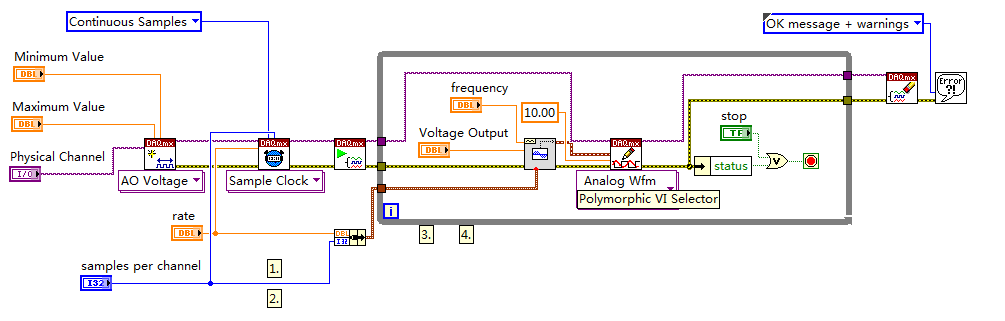
I use USB X series 6356 to my experience. I send out a pulse of tone by analog output channel to an actuator.
And receive the signal of response of a sensor to an analog input channel. I've included a screenshot of VI.
The question is, I get the output of the signal response signal as well.
If I send (via the output channel), a burst of your 10 KHz which begins at t = 0.
I see that the tone burst into my plot of input channel as well (at t = 0).
Please, let me know if I use the good VI (I build it according to multi-multifunction-synch I AO VI of examples).
I use the loop to remove 60 Hz noise (by an average of more than 100 times) signal.
Hi Vishnu7,
From what you describe, it seems that you can meet with some ghosting or crosstalk on your analog input channel. Take a look at this knowledge base article and see if it matches with what you see.
http://digital.NI.com/public.nsf/allkb/73CB0FB296814E2286256FFD00028DDF
-
Hello
My question is about the analog output (0 - 10V) of the myDAQ unit.
On the card, you can read:
"Overdrive Protection +-16 V forever."
Lets imagine the worst case: 0 V output DQA, but outside a battery or anything else is connected with 15 V to the analog output.
Fact an "unlimited" current in data acquisition or protection 'Overdrive' works here and the material is safe to destroy?
The background: I want to OD are protected from transient voltages and toilet on a simple zener diodes clip or a tvs diode...
Thank you all, Markus
Markus,
To use a zener diode as protection, you must also have an impedance of current limiting in series with the source against which you are protecting. The manual for the device of maDAQ indicates that the lines of the AO are pushed by OPA1642 op amps. TI the MSDS for this unit shows the current limiting internal ~ 36 my short circuit with Earth and a thermal shutdown circuit that tries to protect against the terms of overpwer.
However, under your 15 V battery, 11 V zener and 0 V programmed DAQ exit, the situation may be different. The current from the battery through the zener will be limited by the impedance of cables or any type of resistance on the line. This has no direct effect on the myDAQ device, but it will probably destroy the zener unless resistance limits the current to a lower maximum current nominal zener. As long as the voltage at the output of the myDAQ is lower than the internal supply voltage (+/-15 V), on the OPA1642 current limitation should apply. With 11V applied to the output and the value set to zero the device would probably be to try to sink the maximum current for-15 V power supply. Which translates to a dissipation of power of more than 900 mW, which exceeds the rated capacity of the op amp. Themal protection should, in principle, reduce the current to a level that does not exceed the thermal limit under development.
This test can be a costly process. The unit may be destroyed. Given that the maximum current specified for an analog output channel is 2 my and the maximum voltage is 10 V, I would consider a series resistance of perhaps 1000 ohms and clamping schottky diodes at the + 15 V and - 15 V power supply. This will limit the current to 10-20 my in all conditions you have mentioned and would also provide protection to the case where the battery is connected the myDAQ device is turned off. He alsoe does not care about the polarity of the external source. It will drop the output voltage according to the load impedance. If this should be used in a student lab, the calcualtion of this decline is something they should be doing anyway, and would be a small price to pay for protection.
Lynn
-
Acquire the values only when the digital output is high.
Hello
I work with test of transistor, whose door is controlled by the digital release of USB6289, related to BNC2120.
Test plan:
Door 1.transistor is enabled for 5seconds, with P0.0 for example
2. then, everything remains off for 1secondes.
3.p0.1 is used as digital output to activate the circuit passing him curent through in the opposite direction, P0.1 goes high for 3 seconds, PS: Gate is off.
4. the same cycle repeats again.
My question is to store values to the output of the transistor when P0.0 and P0.1 goes high, and these values should not change until my digital outputs respective again go high.
I can access transistor by continiously read out my power supply values.
and in the State off I want to read AI0 because at that time, my power supply is off, so that I can activate the circuit to pass the current in the opposite direction.
Again, my question is to gain the output through power value when P0.0 is high and store them until the transistor turns on.
and even for P0.1, acquire the value of output through AI0, when P0.1 is high and store it until it goes high again.
Hopefully, I'm able to explain my problem clearly.
Please help me.
Concerning
Anurag
Think about what States (object:statemachine and determine when to use sequence Structures) do you want from t0... t(n-1), IF DAQmx generates outputs and/or inputs are absorbed and what needs to happen (event timed out), before move you on to the next 'State '.
type def 'enum' with your different States:
- initialize
- wait (the user initializes times (sec) set for States, or whatever and presses button 'Start')
- T0 (generate DigOutputs, store acquired data AnalogOutput (string output number) the register shift, before moving to the next State > user 'set time' must elapse (Note: the wait function allows you to control the rate of execution of loop and allow the CPU to respond to external events and system tasks and avoid using wait functions at the same time an operation of software...))
- ...
- t(n-1) if ' end (made requirement) "> goto 'stop', ' another (not requirement not)" > goto regardless of 'State '.
- stop
- write a text file of data (string).
-
Timestamp is always converted to universal time?
By applying the function 'get Date/Time' and ' Date/Time seconds to ', it seems that they are forcing UTC after conversion, even if the option for the UTC is false.
I would like to have the actual system date and time available (which represents for the summer time and time zone as shown on my PC) out of timestamp, but instead I get a value for the timestamp value that (I assume) is UTC. When I probe output of timestamp, or the output of cluster, it seems OK. However to estimate the number of timestamp, it is always disabled by what looks like the difference of the DST and time zone (exactly 5 hours).
I tried two different methods and find the same results.
(1) out of ' Get Date/Time ' function directly (which specifies the timestamp will be universal time in its contextual help file)
and
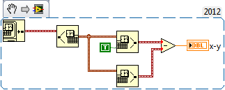
(2) convert the timestamp in a cluster and reconvert it timestamp (as pictured).
In the example attached photo, notice the cluster result (probe 25) shows the correct time (16) when broken down and the probe of timestamp (26) seems correct.
However, when the timestamp of the function "get Date/Time" or function "Date/Time seconds to" is converted to U32, changes of time what time looks like UTC as the timestamp 3485539686 (probe 28) has the offset of 5 hours (21 as shown in Excell sheet calculations included in the image).
I'm not simply subtract 18 000 seconds to account for this difference (as DST or time zone changes may cause problems). I would like to than the actual time of the PC to use for the generation of table.
How can I do this?
Why do the probe points show the time system correct, but just after the timestamp is converted to U32 it resembles the UTC?
You can use GetTimeZoneInformation to get through the time stamp and add/subtract out. It's not like I had to code that WinAPI evoke yet, so I can't provide for you. The return value indicates also advanced.
You can also take your timestamp as you did and convert the cluster and return to determine the offset. I've only done a few testign base with this, so don't know if it works in all use cases. The WinAPI method would be the most robust.
This completes actually missed the date upward, but returns the correct offset.
-
How do the last 4 paintings of a loop output For?
Hi people,
I'm almost at the end of my home. I really hope that someone could help me please.
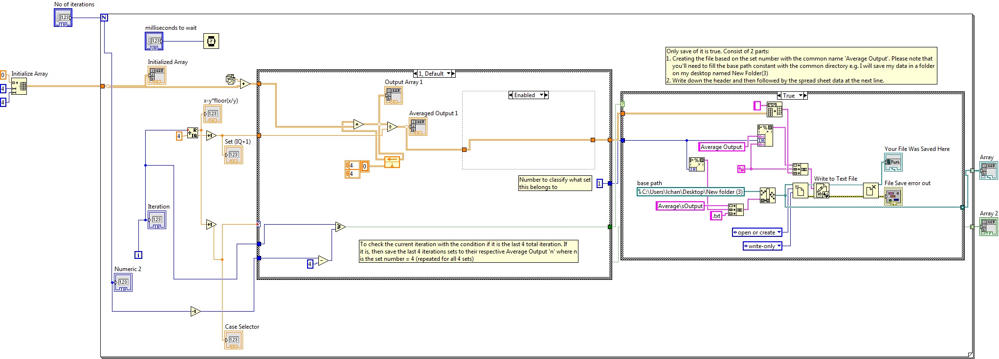
Any input would be welcome. VI attached.Explanation of VI:
I initialize an array.
The random number generator simulates my entry camera.
According to which iteration it is, the data are added in one of the four tables of output.
"x - y * floor(x/y) ' gives a value of remainder of 0, 1, 2 or 3.
'Case Selector' just add 1 to "x - y * floor(x/y) ' for case 1, 2, 3, or 4.
Pictures 1, 5, 9 etc. are added to table 1 (case 1).
Photos 2, 6, 10 etc. are added to table 2 (case 2).
3, 7, 11 etc. are added to table 3 (case 3).
Shots of 4, 8, 12 etc. are added to table 4 (4 cases).
Average output displays the average value or total divided by the number of photos stored in this table ("Set (IQ + 1)'").My problems are:
(1) I would like to output only the last 4 sets of data from different average output files, 1, 2, 3, and 4 to 4 (i.e. under .csv what is displayed on the screen in indicators "average output was 1, 2, 3 and 4 at the end of all iterations.)
Where should I put my file save the diagram disabled so that it does?Put outside the main loop with automatic indexing on gives me a file with all previous data. (This is not feasible under my number of shots should number in thousands)
Put outside the main loop with automatic indexing for off gives me only the last data series. (I need the output for 4 tables, not only the last run)
Inside of the main loop to put (as shown) gives me the same number of files as the number of iterations. (Once again not possible due to the large number of files that will be generated and slow down the camera capture)
In order to capture fast camera, I wish that these 4 files output only once the entire image capture are over.
2) would preferably name the file once and for the program to add "(1)', ' (2)', ' (3)' and '(4)' file name tables"output on average"but appropriate file path controls are an another big headache for me.»»»
3) PS is the initialization of an array enough not to use the memory manager? Or should I initialize 4 Bay?
I am using Labview 2010.
Thank you very much
CharleneHi Laura,
I assume that you want to store the 4 x 4 table of average production for the last 4 iterations (correct me if I'm wrong). If so, I've set up the example as shown below:
So, basically, what I did is I created a comparison group to check if the iteration is the iteration total last 4, you have defined. I have included a number to each of the business structures to set in which case it belongs to. The comparator will pass a Boolean result to the structure of the housing that contains the algorithm for writing a file. Since you mentioned that you want to create a file for each of the case, I created as a way to build to create the customized for each case file name. You will notice that there is a concanate string.vi that allows me to customize the name of the file. Since the common file must be exit average, I take the digital constant from the structure of the deal and convert it to a string and concanate to make it in e.g. output average 1. Please note that you need to put a basic path such as in my case, I want to save in the folder named ' New folder (3) "to my office.
The writing on the case folder occurs only if the condition is true (that is, the last 4 iterations of the loop for)
Once done, I created the header and write it in this text file and followed by data from spreadsheet on the next line.
I enclose the code for your reference. I would like to know if this is what you wanted.
Thank you
Warm greetings,
Lennard.C
-
How to get an average displacement of the last 5 lines that were NOT NULL?
I have a question involving a moving average, and it works fine using:
AVG (col_x) more (partition col_a, col_b, col_c lines between 5 preceding and 1 preceding arrested)
However, I want to change this option to give the average of the last 5 lines which were non-null. Does anyone know how to do?
For example:
create table sample_table)
col_a varchar2 (10),
date of col_b,
col_c number (2),
col_x number (5.2)
);
insert into sample_table values ('X', trunc (sysdate), 1, 1);
insert into sample_table values ('X', trunc (sysdate), 2, 2);
insert into sample_table values ('X', trunc (sysdate), 3, 3);
insert into sample_table values ('X', trunc (sysdate), 4, 4);
insert into sample_table values ('X', trunc (sysdate), 5, 5);
insert into sample_table values ('X', trunc (sysdate), 6, 6);
insert into sample_table values ('X', trunc (sysdate), 7, 7);
insert into sample_table values ('X', trunc (sysdate), 8, null);
insert into sample_table values ('X', trunc (sysdate), 9, null);
insert into sample_table values ('X', trunc (sysdate), 10, null);
insert into sample_table values ('X', trunc (sysdate), 11, null);
insert into sample_table values ('X', trunc (sysdate), 12, null);
insert into sample_table values ('X', trunc (sysdate), 13, null);
insert into sample_table values ('X', trunc (sysdate), 14, null);
insert into sample_table values ('X', trunc (sysdate), 15, null);
Select t.*,
AVG (col_x) on myavg (partition col_a, col_b, col_c lines between 5 preceding and 1 preceding arrested)
of sample_table t
order by 1,2,3;
COL_A, COL_B, COL_C MYAVG COL_X
---------- ----------- ----- ------- ----------
X 15/01/2015 1 1.00
X 15/01/2015 2 2.00 1
X 15/01/2015 3 3.00 1.5
X 15/01/2015 4 4,00 2
X 15/01/2015 5 5.00 2.5
X 15/01/2015 6 6.00 3
X 15/01/2015 7 7.00 4
X 15/01/2015 8 5
X 15/01/2015 9 5.5
15/01/2015 X 10 6
X 15/01/2015 11 6.5
X 15/01/2015 12 7
15/01/2015 X 13
15/01/2015 X 14
X 15/01/2015 15
15 selected lines
What I really want is:
COL_A, COL_B, COL_C MYAVG COL_X
---------- ----------- ----- ------- ----------
X 15/01/2015 1 1.00
X 15/01/2015 2 2.00 1
X 15/01/2015 3 3.00 1.5
X 15/01/2015 4 4,00 2
X 15/01/2015 5 5.00 2.5
X 15/01/2015 6 6.00 3
X 15/01/2015 7 7.00 4
X 15/01/2015 8 4
X 15/01/2015 9 4
X 15/01/2015 10 4
X 15/01/2015 11 4
X 15/01/2015 12 4
X 15/01/2015 13 4
X 15/01/2015 14 4
X 15/01/2015 15 4
15 selected lines
concerning
Neil
Hello
Here's one way:
WITH got_avg AS
(
SELECT T.*
AVG (col_x) OVER (PARTITION BY col_a, NVL2 (col_x, 1, 0)
ORDER BY col_b, col_c
LINES BETWEEN 5 PRECEDING
AND 1 PRECEDING
) AS myavg
OF sample_table t
)
SELECT col_a, col_b, col_c, col_x
LAST_VALUE (myavg IGNORE NULLS) over (PARTITION BY col_a
ORDER BY col_b, col_c
) AS myavg
OF got_avg
ORDER BY col_a, col_b, col_c
;
Too bad, that we cannot use the IGNORE NULLS with AVG function.
Maybe you are looking for
-
I currently use the PC of Quicken version for my bank details / checkbook. I now also have a Mac but quicken for mac is not well received. Is the iBank program compatible with quicken data from a PC to Mac? The iBank site says it's... Thank you...
-
My mother has been contacted on April 28, 2012, by the Digital River company
My mother has been contacted April 28, 2012, by the Digital River company, telling him that his pc was infected and if she wasn't buying Windows security she might as well throw his pc. Is this company associated with Microsoft? If so, you should be
-
Hello I have a problem with my audio beats after windows update 8 for windows 8.1. I tried several times to uninstall and then reinstall the latest audio driver and still no positive result. I really have no idea how to fix this. Note: 1. my computer
-
HelloI'm trying to create applications with shipment.Watch it (Ariane Mail Apex wire)https://Apex.Oracle.com/pls/Apex/f?p=71697:2I have a problem with attachments. I know how to add attachments via the BLOB of a table or the FILES of APEX APPLICATION
-
How to make a record of sharing
I want to do a SQL cluster, there is no storage.So my question is "can ESXi5.0 do a sharing disc? »If can, please give me some advice how to make.If not, can you give me some advice how should instead shared storage.Thank you