Report of derived measures
Is there a way to get a report on the measures derived by cartridge?
You may want to consider the metric diagnosis derived under Administration-> data dashboards
Once in the dashboard, you can export the data in a report cliicking on the customizer on the right side of the table.
There is a column of cartridges
David Mendoza
Tags: Dell Tech
Similar Questions
-
Need help with report of scale measure/tool change area
I try to use the measure area tool in Acrobat ms on a pdf plan I'm working on that. The EHR Architecture scale is 1/8 "= 1'. So I will try to change the ratio of the a.125 in = 1 ft scale in order to account for this, but it automatically rounds up a.13. Is there a way to avoid this and keep the number I had intend without it rounded up?
Hi, Elia,.
I don't see a way to add more than 2 decimal places to the measure tool scale ratio.
You can send a request to feature here:
Adobe - feature request/Bug Report Form
Kind regards
Rahul Tyagi -
Need help with the function or metric derivative to calculate percentages of threshold for a measure
Hi, first post to the community that I am a n00b Foglight needing help.
A thing (in fact the only thing) I like Microsoft SCOM is how this graph of the availability of a metric, and I want to do the same thing in Foglight. I understand that this could be a derived measure or a function, I need, but am a bit lost right now.
Let's say I have a metric and created thresholds as follows: normal included 0, 50 inclusive, warning critical 75 inclusive, fatal 100 inclusive + 9999 included. The metric is measured every so often and more often (99%) of the time it's normal. I want to visually represent that fact, together with the percentage of time that he spends in the strips of quick, critical and fatal alert threshold.
For the dashboard but mainly reports I am looking for the percentage of time that the metric through each of the bands of threshold and put them in some form of chart, preferably very similar to how SCOM it: -.

I would also like to increase this visually with a quantification for the oriented numercally, in order to insert values in the report for clarification would be great too, for example:-Normal:-99% 0.5% warning critical Fatal 0.1% 0.4%
I think of what I have already learned that we have to include a 'blue' band for threshold indefinite in order to operate on a regular basis for any measure.
I do not seem to come up with this concept in Foglight but I think it could be very useful to have something. Any help is most appreciated.
Health and alarms is a standard display which can be used on any object topology. You can access it from the data browser and should also be able to specify this dashboard as a preference in personalized dashboards.

Here it is in a custom dashboard:

-
change the properties of the report axis (together begin and end)
Hey everybody,
I am a beginner with DIAdem reports and close to despair that I have yet found any solution.
I wrote a script, which produces reports of various measures with 9 pages (3 2D-slots each, a total of 27 lots).
Now, I want to put the beginning and the end of the x-axis of certain specific parcels.
First question: tiara offers something similar to an Object Explorer (for easy access to the names of the objects drawn in a report)?
I created two GlobalDims called x_time_begin and x_time_end to set these properties, but I don't know how to access these variables in the report (tried @... @ and @... @ the 'Axis settings' tab).
These variables change for each measure, so each report has a different set.
The presentation of the State is responsible from a set of. TDMS files and is not altered in the script.
How can I find the name of a specific plot in the report can access?
Is it possible to define the range of the x-axis in a variable at all?
Best regards
Nils
Hi Nils,
It is possible to set the x-axis of begging and positions in the scripts end (see text below). When you create a report object in the script you can name it anything you want to access later. Otherwise, I think that the default name is the name of the object, of the number (for example the 2D first table is called "2DTable1")
Dim oMy2DAxisSystem, oMyXScaling

Report.NewLayout

Set oMy2DAxisSystem = Report.ActiveSheet.Objects.Add (eReportObject2DAxisSystem, "My2DAxisSystem")

Set oMyXScaling = oMy2DAxisSystem.XAxis.Scaling

oMyXScaling.AutoScalingType = eAxisAutoScalingManual

oMyXScaling.Begin = 0.01

oMyXScaling.End = 100
Hope that helps,
Sadie
-
Derivative Rulette metric not disabled "no trigger.
I thought I'd throw it out there that I don't know why my derived metric is triggering not even if I am selecting calendar leads and check the box 'enable the trigger without data '. I have tested the metric script without problem and can not find a reason why it should not run at the scheduled time.
2012-11-29 13:17:18.226 VERBOSE [utility-1-wire-45363] com.quest.nitro.service.derivation.DerivationCalculation - DerivationCalculation for "Cluster_Growth_Rate_New" on "VMWCluster" calculated by (ds = server.get ("DataService")...) has rulettes disabled for the following reasons: no trigger (1 rulettes)
- [[(numdays = 0) {break}-} now = ds.retrieveLatestValue(scope,_"virtualMachinesPoweredOnCount").getValue (.max) / / retrieves the current value growthRate = Math.ceil (((now-then) / numdays * 30)) / / calculate the growth rate current growthRate return]] >
@John - I put the coding offers in the script and found that the derived metric even was not getting a message in the log.
@Thomas - I have try with "entry, exit and Enter and Exit" without result
I started to dive a little more and found that my other derived measures 3 which took place successfully for months were no more calculation. I restarted the server and all measures derived including the growth of clusters have been executed successfully. It seems to be some kind of problem with the server and not the derived metric.
-
Incorrect aggregate results with a total of 11.1.1.7.140527 report-oriented
We are moving to OBIEE from version 11.1.1.6.0 to version 11.1.1.7.140527. We noticed that some of the aggregated results are incorrect in the new version. If we edit the columns of measure in the analysis to disable the State of total aggregation based on the report on the measure columns, then we get the correct results.
Is this a bug in the new version? We did not have this problem in 11.1.1.6.0. Based on the report totals are enabled by default, so we need for our users to disable this function for each column as they add and for each measure on the existing analysis column to ensure correct results. This is not feasible.
Is there a way to manage it globally in the repository or with some setting overall so the total report-oriented are not on by default?
Thank you
Travis
The problem turned out to be an incorrect sort on our ODBC data source type. He has been to sort based on hexadecimal values rather than sorting based on the ID of the language. Database SORT_ORDER_LOCALE in the repository functionality has made the English-United States, so he expected the data extracted from the database to sort based on the English of the United States. When the data has been sorted by hexadecimal values, numbers have been sorted after characters. This caused a problem when a dimension column had some values beginning with numbers and others from alpha characters, and the BI server would assemble multiple result sets. The rows with values of dimension from numbers were missing data in some columns. We turned off totals based on the report, the physical SQL has been changed so the Server BI had no need to assemble result sets. That mask the problem, but was not the solution.
-
I recently updated several derived measures I use and finished with duplicates. I deleted the old copies of the list of metrics derived, but still, they show in the data and could lead to confusion in the future. Is there a way to remove these measures in the data tables?
Thank you
Wyatt
Hey Wyatt,
You can find the solution on SupportLink in Solution SOL73487.
Example:
def ts is server. TopologyService
def tt = ts.getType ("HostStorage")
def updateTT = ts.beginUpdate (tt)
updateTT.removeProperty ("ktest_space_available")
TT = ts.endUpdate (updateTT)
Kind regards
Brian Wheeldon
-
Delay in navigation on the last page of the report
Hi all
I have a report that derives about 50 K of data lines. I am able to display 25 records at a time. However when I navigate to the last page by clicking on the arrow that would show me the last page, it takes unusually long.
What are the settings in the file NQSConfig.INI checked or changed in order to improve this behavior? I should cache the table that is the source of the data, as well?
Enjoy all this customer an overview...
Kind regards
SamThe arrow to the right (the one with the asterisk) does not go to the 'last page '; rather, it displays the whole report, if all 50K lines. That's why it takes a longer time.
-
Stand-alone table in the drop-down and limit values in the report
Hello
I report where the measured values should be limited based on the threshold value table. Values threshold has the values below.
Table of threshold:
ID of threshold threshold values descr
13345 10000 initial
13346 departure 20000
13347 30000 initial start
13348 40000 end
13349 end last 50000
This table is independent of the star for OBIEE report schema and created for the user, given the threshold value.
Shud threshold shown falling down the values and the drop-down list values invites is always GTE to 10 000 by default. The report shud display measurement values GTE 10,000 in the columns of 4 measure of the report written by deafult, based on the work of prompt and default shud according to the user's selection in the menu dropdown.
I intend to apply it using the variable of the presentation, but when I select GTE in the command prompt, this option is not present. Please throw some light on this issue.
Thanks in advance.Use is equal to the operator in the guest... change the show section for all values of sql result... after that, change the formula in the column to the case where 1 = 0 then
else 1 end... now you can make a variable presentation... use this variable in your report with is liked this operator in your report... HTH... Published by: Vincent on July 20, 2010 10:57
-
East of the calculations on the possible Union report columns
Hi all
My report has two measures that each is based on two dates different dimensions.
1 > measure 1 based on the Date of the order
2 > 2 of measure based on the date of purchase
In my report, I would like to show
Column1 column 2 column 3 column 3
Date by Dimension (union of the Ordr Date and purchase Date), action 1, measure 2 Measure1/Measuure2
Q12009 220 100 22%
I could reach the column 1, column 2, column 3 with the reports of the Union, but not able to achieve 3 column i.e.Measure1/Measure2. Is this possible?
Regarding
PradsHave you tried using the FILTER... USING the feature?
(1) on measure a, click the fx button.
2) click on the filter button.
3) go to your list of selection on the left side and then click on "Order Date". It appears in the window. Click on 'OK '. Now you have the filtered column based on the Date of the order.
4-6) repeat steps 1-3, except choose "Date of purchase" in the dimension column.
(7) Finally, enter a column, click on the fx, delete the content and take the step 3 column and divide it by the column in step 6. This gives you the column Measure1/date2.
-
Level - Can Reporting someone please explain this attribute?
All - I am a newbie on Siebel on demand but creating reports with other tools for years. I recently came across some reports that I inherited that constantly give us bad. These are basic reports that look at the number of calls, meetings, etc. for a given user. What we see is that we used this statement attribute level to filter, but according to the Manager of logging level in it cause problems. Some people cannot see the data, and some receive a massive amount of duplicated data.
When all is said and done, we are looking for a simple list of Manager-rep of counts of these activities. After looking at the value of level reporitng it would look like an indicator of the relative position of the level lower in the reports - to the hierarchy. We will generally filter level = 0 (or maybe 1) reports more but what I want is a way to control based on the user. My requirement is to have the level they can see and retail at a level more low but I don't ' fully understand how that is created or how can I use system variables to determine the level of user control.
Anyone who has the news of background on this page or how I can order a basic report anaylytic in more manageable to show my stuff and subtotals to a level more down which would be greatly appreciated.Not sure if I can help with the specific report, but I'll try more of light level Reporting.
In a report which is flush with the dimension possessed by the user, you can find the Reporting level field. Each user belongs to a reporting hierarchy, derived from the "Reports To" value in their user profile.
The best way to see it is to create a simple report with the Email of the user level reports and email Manager. This will show you the Manager at each level. You can use this to expose and filter on the complete management hierarchy.
Level 0 = user. All users have a value of themselves as Manager at level 0.
Level 1 = reports to-which reports directly to the user.
Level 2 + = towards the top of the chain...You can take a look at some of the predefined reports to see how this can be used to create reports based team, as 'Team Pipeline Analysis', ' team sales analysis of efficiency "and"analysis of the Team activity. You can open all the pre-buiilt reports as well as the starting points.
-
OR DC Soft Front Panel, minorbug, small bug with the PXI-4110
Hello
The NI DC Soft Front Panel V14.0, with the PXI-4110, scrolling to negative tension, works as expected to-10V, but then returns to 0. If we change from - 1V procedure, it goes...-8-9,-10, -1, -2... instead of-8-9,-10, -11, -12...
Everything about her, a simple thing that I miss is a switch for all three voltages.
(Also, IMO, it would be logical for negative tensions with the arrow pointing down, not more).
My 2 c
Hello Janaf,
I completely agree with two of your statements, I tabled a report of corrective measures that you can monitor in the next versions of DCPower to see if this is fixed with the FPS. CAR number: 512257
I've added notes that only manual insertion of numbers - less than 10 works and that it was not logical to use arrow increment or upward arrow to reduce the output voltage.
-
I am a new user of Labview, so it's a little intimidating. I am using a cDAQ-9188 with several modules but I have problems with one is the 9411 is used to measure the speed off the coast of a torque meter.
I joined the program I put in place. What I want to do is to measure the number of edges on a 3 second interval so that I can divide by the number of pulses/turn * 60 * 1/3 to receive the RPM. However, the number of edges behave linearly as I expected. I measured the speed of the shaft with a light strobe and represented graphically it vs the number of edges. The results are attached to the excel file.
What Miss me? The number of edges should not increase as speed up the tree, or I'm going about this all wrong and is not what I think I am?
Thanks in advance.
Ahh ok, that make more sense - it seemed like a strange to report a couple measured, way but now I understand that your torque sensor also rpm through this collection of speed option and that's what you ask the subject (I can't see not how pulses/turn the sensor is on the site Web of Honeywell however, do you know offhand?).
The software timing 3 seconds will implement much of the variability in your measure but would not explain the strong negative correlation between the RPM and the speed sensor (we're talking several ms of non-determinisme for a second window 3) output frequency. Finally, you'll want to solve this problem as well, but it is not your problem right now (as an aside - it would be actually more accurate to measure the frequency of the signal encoder using the 80 MHz as a reference time base and average the result on a second window 3, the general idea is sort explained in manual of 9188 here but I digress).
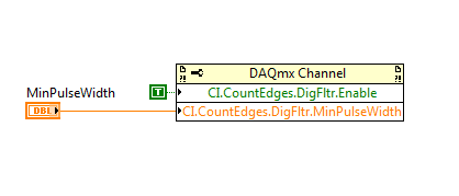
I think it is more likely that the signal from the speed sensor is a bit noisy (pretty typical of optical encoders) and then transitions the 9411 is picking up multiple edges. A slower RPM equals longer transitions and therefore more false edges. It is just a hunch, but that's what I can think of on the top of my head that could be causing what you see (if read number of pulses is higher than what you expect, given the pulses/turn of the sensor through all ranges of RPM that it would support my theory). If you want to ignore the method of measurement for a second and try to solve the problem of noise (assuming there is one), you can add the following property node to your existing code before you begin the task:
You can start by setting MinPulseWidth to 6.4us (which is one of the built-in clock dividers available for PFI filters on the 9188). You want the MinPulseWidth be short enough to ensure detection of a legitimate impulse, but long enough to block all wrong edges that occur during transitions.
Best regards
-
reference level range and vertical
What is the relationship between the reference level range & scope vertical?
Alann Hello,
High-speed digitizers help NOR is very useful in the definition of these types of words.
Help ' reference levels are high, low and mid range values you set for take the time to climb, descent, positive width, negative width, positive cycle duty and report negative cyclical measures.» Reference levels are usually set up in terms of percentage of the wave, that you purchase. By default, the low value is 10% of the wave, the average level is 50% and the high value is 90%."
Also of scanners high speed OR help "vertical range is the duration of the peak to peak voltage a digitizer that can measure the level of input connector.» Most scanners have several choices for the vertical range. »
The only relationship between these two concepts is in the fact that the vertical range defines the peak values of the signal input, which also limits your reference levels of high and low.
If you have not installed the driver NOR-Scope, but still want to reference the help file is available for download here.
-
Control of canoe of unit tests in LabVIEW on ActiveX
Hello
I want to run the unit tests of canoe in LabVIEW using ActiveX.
EnvVars and sysVars in canoe handling was not a big deal, and there are plenty of examples here.
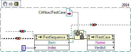
But the unit tests of handling is quite difficult. Canoe help file shows this way in the object hierarchy:
I solved the problem with the help of vector Support. They sent me the following c# example:
MApp CANoe.Application = new CANoe.Application ();
CANoe.Configuration mConf = (CANoe.Configuration) mApp.Configuration;
CANoe.TestSetup mTestSetup = (CANoe.TestSetup) mConf.TestSetup; Test settings window
CANoe.TestEnvironments mTestEnvs = (CANoe.TestEnvironments) mTestSetup.TestEnvironments;
CANoe.TestEnvironment mTestEnv = (CANoe.TestEnvironment) mTestEnvs [1]; Test environment (file *.tse)
Console.WriteLine ("Name" + mTestEnv.Name);CANoe.TestSetupFolders mTestSetupFolders = (CANoe.TestSetupFolders) mTestEnv.Folders;
CANoe.TSTestModule mTSTestmodule = (CANoe.TSTestModule) mTestEnv.TestModules [1];
Console.WriteLine ("Name" + mTSTestmodule.Name);CANoe.TestSequence mTestSequence = (CANoe.TestSequence) mTSTestmodule.Sequence;
Console.WriteLine ("Count TestSequence" + mTestSequence.Count);
CANoe.TestCase mTestCase = (CANoe.TestCase) mTestSequence [1];
Console.WriteLine ("Name of Testcase" + mTestCase.Name);
mTestCase.Enabled = false; disable the unit test - XML and structured NET only module.CANoe.TestReport mTestReport = (CANoe.TestReport) mTSTestmodule.Report; Access to the report
CANoe.Measurement mMeasurement = (CANoe.Measurement) mApp.Measurement;
If (! mMeasurement.Running)
mMeasurement.Start ();mTSTestmodule.Start ();
I realized that you can cast the ActiveX object references to another class of the child in the following way:
It was the right solution and I want to share with you.


Maybe you are looking for
-
I'm having difficulty trying to restart and update my iPhone 7 using the Home button and the sleep/wake button at the same time, when I do my phone takes a screenshot of the home screen. Should I turn off my Touch ID? Basically my home button button
-
Path and file name of the message is too long to be copied-how fix?
On Windows 7, TB ver 24.6.0, I use a program called SecondCopy to copy my email when my C drive on my desktop to our file server. I get several messages each day like this one for the copy be saved on our network data sharing: 04/07/2014 21:07:16 - f
-
4MOT/4/40000003: drive HARD-1383 and 4MOT/4/40000003: drive HARD-1373
Does anyone know the significance of the errors 4MOT/4/40000003: drive HARD-1383 and 4MOT/4/40000003: drive HARD-1373 that occur when you run Apple Hardware Test (AHT)? I guess it has to do with the hard drive by noticing the "HARD drive" code. IMac
-
Okay, so my problem is that Disk Defragmenter, disk checking and the system restore will not work.
I tried to go to the c drive and right on it and going click Tools then error checking, but it did not work. I tried dfrg.in and right click to install. I tried to use cmd fixes, I found on the net. I tried a lot of bugs, but nothing helped. Any idea
-
Problem list data execution prevention:
I have a Vista Home Basic x 32 - desktop I have 2 or 3 programs to my list of Exception Data Execution Prevention (DEP) that I won't be there anymore, I removed the programs, but every time that I re - open it the back of DEP, deleted Programs window