RMS / amplitude and phase to the fundamental frequency
Hi, does anyone know how to find the RMS or amplitude and phase to the fundamental frequency of a signal measured in Labview?
I tried with the Analyzer for harmonics of buit - in, but he can't give the values of the phase angle. I also tried the FFT VI spectrum, but I don't think the results are good.
Thank you.
Hi again
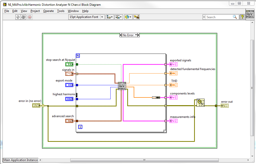
Harmonic distortion Analyzer is a polymorphic VI, this means that if you connect a single signal in and then you get a unique signal, and if you connect a table of signals in out you a table.
The VI I is not polymorphic, but you can easily change to work with multiple signals. If you look at the standard implementation for the harmonic distortion Analyzer N-channel then, he simply called the channel 1 harmonic distortion Analyzer a loop for. So you can easily call my VI in the same way. See attached screenshot:
Best regards
Anders Rohde
Technical sales engineer
National Instruments Denmark
Tags: NI Software
Similar Questions
-
find the fundamental frequency & treatment
Hello
I am in an interesting situation, I am processing a signal (Labview8.2) looking for a fundamental frequency using the Analyzer SINDH and harmonic distortion Analyzer, but I need to build again the signal using only the basic and some of its harmonics frequency signal,
Suppose that some time, I need to add up to 5 harmonics built the signal as well as the fundamental frequency, and some time the number of harmonics must make six or another value.
in this part, I'm hard to find, can someone help me? There is a VI that can directly do the job?
Hello!
Looks like all you need is the filtering.
Kind regards.
-
Re: Satellite L735 PSK0CE: WLan and BT use the same frequency
Hello world
I reinstalled my Toshiba Satellite L735 - PSK0CE with Windows 7, until the one and download all the drivers for it, I did not too Wirelles conection, Lan and the wirelless use the same channell radiofrecuency than Bluetooth
Can you help me with this problem?
Thanks in advance
Post edited by: aku - aku
Hello
WiFi and BT use the same frequency. For the most part this isn't a big problem but in case you notice a few connection problems with WLan or BT, you must disable WLan using BT or must turn off BT if you want to use the WLan.
-
Bad results value amplitude and phase
I try to add two Phasers of tension and to get incorrect when simulated results on Multisim using the frequency unique AC analysis. I changed the amplitudes of analysis AC from both sources to their respective values of 20 and 15 volts. The result of the addition should be size = 25 volts peak and phase = 66.87 degrees, which does not match results of Multisim. What I am doing wrong?
Thank you in advance.
You must click twice on the fickle source V1 and V2 and the "AC size' and the 'magnitude of AC Phase', change the settings.
Also, depending on your preference, select Options of Simulation global preference, time = 0 if you want the right to shift to change phase or left, you can configure it here. This setting affects your calculation of phase.
-
measurement of the phase of the signal
Hi all
I'm trying measureme the phase of the sine wave.
I produced sine waveform and give '' measure spectral '' VI express to measure the magnitude and phase. The block of spectral measure gives picture of the spectrum amplitude and phase with the difference in frequency of 1 Hz.
The input signal is 10 Hz sine wave. so I checked the 10th item in the table of phase and amplitude. I'm getting the right size. but I get different values for phase measurement
For example, if the input signal of 0 degrees phase shift, the spectral measure gives as-90 degree. If the input signal has the phase shift of 20 degrees, the measure blocks gives as-70 degrees.
I can't able to find that how to pass this phase-90 degree occurs.
Kindly help to solve. I thank in advance.
with respect,
Renaud V
Renaud V,
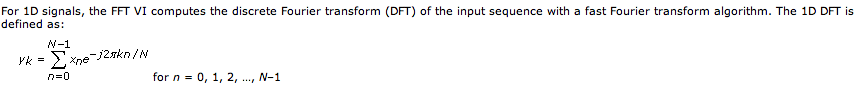
The spectral measurement VI uses the FFT internally. In the detailed help for the FFT, the following definition is displayed:
Note that exp(-j*2*pi*theta) = cos(2*pi*theta) - i * sin(2*pi*theta). This phase shift is defined in respect to the cosine, and non sine, explaining the 90-degree turn.
Lynn
-
How to get the values of phase of the harmonic component digitally?
Hello
Basically, what I'm trying to do is to analyze the quality of acquired signals. What interests me are amplitude and phase at some frequencies (for example 50 Hz, 150 Hz, 250 Hz, etc.) of a waveform. I tried to use "measurment spectral express VI' to achieve my goals. It works well, but so far, I can handle only show spectra in graphics. Then, I tried to use "harmonic distortion Vi' to obtain the amplitudes of harmonic components digitally and it's absolutely perfect. My question is that how can I get the phase of the harmonic components digitally?
Thank you very much
Hao
FFT and a manipulation of the results seems to work quite well.
I used some tones and noise Waveform.vi to generate a test signal. .Vi (Mag Phase) FFT spectrum analysis the signal. I find the amplitude peaks and extract the phases in these places. Results are quite close to the entrance of the values even when the noise is larger than some of the harmonics.
Lynn
-
Loop of calculation of gain and phase in multisim
I am trying to simulate the loop gain and phase for an oscillator in multisim. I use the Middlebrook method and can get the gain in current and the gain in voltage by using the function "add the words" in the analysis. Then, I need to use these winnings to calculate the loop gain and phase using the equation T = ((Ti*Tv)-1) /(Ti+Tv+2), where Ti and Tv are respectively the current and voltage gains. I have been unable to bring the last expression and will appreciate any help.
Thank you
André
André,
Yes, the Middlebrook analysis technique can be implemented with Multisim. Please see the circuit below as an example on how to apply this method in Multisim.
Let me know if you have any questions.
Kind regards
Pat Noonan
National Instruments
-
Frequency measurement and phase of a square wave using to extract the information of your unique vi
Hi all
I'm trying to measure the frequency and phase of a square wave from a data acquisition card using vi retrieves your unique information. So far, the frequency can be measured precisely, but there are a few problems with the measurement of phase.
I have attached a sample program here. I generate the wave square using Square Wave PtByPt vi. The default sample size is 1000. When I put the frequency = 7.43, phase = 80, the frequency can be measured precisely, but the phase is completely. Is there something wrong with my program?
Thank you very much for your help.
Best regards
A square wave is not a single signal ;-)
If you have a square wave use the edges to make measurements.
-
Amplitude varying on the change of the input frequency
Hello
I using NOR-5752 scanner to measure the analog inputs of high frequency. NOR-5752 is connected to the module FLEX RIO 7966R and entry to the NOR-5752 is provided using the SMB-2145 terminal outlet box.
Now, I'm the animals the 0.5Vpp @ different frequencies of tektronix generator of functions directly and by measuring using the digitizer. On the change of the frequency, measured amplitude is changed.
All,
For the NI 5752 frequency response strange behavior is expected. CDA in NI 5752 is the TI AFE5801 (http://www.ti.com/lit/ds/slos591d/slos591d.pdf), and if you look at Figure 19 (p.13), you will see that frequency response of the ADC is only flat after about 1 Mhz. I checked this with our R & D Department and they said they are not aware of any combination of parameters that gives a uniform frequency response at these low frequencies.
If a flat frequency response is necessary for these lower frequency ranges, then the 5751 NOR is much better suited because it has a different ADC. (http://www.ni.com/pdf/manuals/375602b.pdf) The frequency response of this device is very flat in the low frequencies (see Figure 11 p.15).
So both devices, NI 5752 and the 5751 OR are designed to measure different frequency ranges. I hope this helps.
-
PXI-5412 - discontinuities and dynamically modify the frequency with niFgen nodes of property
I'm trying to find a way to eliminate discontinuities and change frequency/amplitude on the fly. Is there a simple way to do this?
Basically, my ultimate goal is as so:
Table:
Start Stop Freq Freq dt
1 100 10
100 1000 5
1000-5000-10
When you start at 1, then move to 100 after 10 seconds. Then you would go from 100 to 1000 after 5 seconds. And finally, you would go from 1000 to 5000 in 10 seconds.
I use the niFgen Util creation frequency sweeping of data VI to create all the necessary frequencies.
I use nodes of property niFgen to try to achieve. I use a simple loop to move through a frequency table, and I update the frequency as follows:

I have everything set up and works, the only problem is that I have large discontinuous jumps whenever the frequency gets really changed. Unfortunately my oscilloscope are boring with the Print Screen function, so im trying to recreate using MS Paint:

Clearly not the best artist ever, but you can get the general idea. I get these discontinuities in the shape of V that are particularly sensitive to the peak of a wave.
Someone at - it a good suggestion on how I should go about it? I'll put in place the generation as follows:

Looks like you are using the operating mode Standard to do this, correct? The best way to go about this would be to use the frequency list mode, but the 5412 doesn't have this feature. I have seen documentation that the use of property with Standard function nodes can definitely cause these kinds of discontinuities. Another method is to use the arbitrary sequence mode, take a look at the niFgen "Arb Example.vi séquence" in the finder for example LabVIEW as a good reference on how to do this.
-
How can I quickly get its main value of amplitude and frequency of measurement of Spectra
See attached vi. Very well, the chart, I see that the dominant amplitude is 3 with dominant frequency of 100 Hz. But how to do that 3 and 100 of the value from the waveform data in a variable double?
I think I have the output waveform for measurement of the Spectra vi table and then do some math on it maybe high percentile or something, but that is awkward! Is there a special feature that can quickly the value of amplitude and dominant frequency?
O! blind me! Use max array and index. Solved already!

-
Hello world!
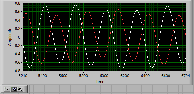
First of all, I use a USRP as a transmitter to emit a sine wave (the signal is exp(j2*pi*f*t)), and then I use the external clock to synchronize the two USRPs (Ref as PPS in are connected to the clock) as receivers. Receivers are in sync, and they are at the same distance from the transmitter, I thought that the signal they receive should have a nearly the same phase. However, in practice, the phase shift is big enough, and this problem really confuses me.
It's the received signals of 2 receivers.
Yes. What you observe is expected.
Near the bottof of this document read the area 'alignment Phase vs Phase coherence '.
http://www.NI.com/white-paper/14311/en/
And also, for the alignment phase, see the following 'Angle of arrival detection with NI USRP '.
https://decibel.NI.com/content/docs/doc-25716
Erik
-
USRP: Time and phase of synchronization for the location of the source?
Hello
I used 2 USRP in reception. They are connected together via a cable Mimo.
I want to locate the source of the issuer. So I need to synchronize the two receivers.
I did the constellation to the two USRP:
1 - with identical cables 2 - with different cables.
(figure: attached files)
I have synced my receivers (in time and phase)?
Please help me
Best regards
-
Synchronization of the inputs and outputs with different sampling frequencies
I'm relatively new to LabView. I have a NOR-myDAQ, and I am trying to accomplish the following:
Square wave output 10 kHz, duty cycle 50%.
Input sampling frequency of 200 kHz, synchronized with the output that I get 20 analog input samples by square wave, and I know what samples align with the high and low output of my square wave.
So far, I used a counter to create the square wave of 10 kHz, display on a digital output line. I tried to pull the document according to (http://www.ni.com/white-paper/4322/en), but I'm not sure how sample at a different rate than my clock pulse. It seems that this example is intended rather to taste one entry by analog clock pulse. There may be a way to create a faster clock (200 kHz) in the software and use that to synchronize the analog input collection as well as a slower 10 kHz output generation square wave?
I eventually have to use the analog inputs to obtain data and an analog output to write the data channel, so I need the impetus of the square wave at the exit on a digital PIN.
How could anyone do this in LabView?
Hi Eric,.
All subsystems (, AO, CTR) derive from the STC3 clocks so they don't drift, but in order to align your sample clock HAVE with pulse train that you generate on the counter, you'll want to trigger a task out of the other. I would like to start by a few examples taken from the example Finder > Input and Output material > DAQmx. You can trigger GOT off the train of impulses, start by Gen digital Pulse Train-keep -you probably already use a VI like this to generate 10 k pulse train. AI, start with an example like Acq Cont & chart voltage-Ext Clk - Dig Start.vi-you'll want to use the internal clock so just remove the control of the "Source of the clock" and it uses the internal clock. From there, simply set the "Source of the command" either be the PFI line generates the meter, or ' /
/Ctr0InternalOutput '-assuming that you are using the counter 0. You'll want to make sure that the start of the task HAVE faced the task of counter I is ready to trigger off the first impulse. They should be aligned at this point. For debugging, you can use DAQmx export Signal to export the sample clock - you can then brought the train line and the PFI pulse to make sure that they are aligned.
Hope this helps,
Andrew S
-
square pulse time rather than the sampling frequency and size dependent frequency
Anyone know if it is possible to create a pulse square with its dependent on the frequency at the time rather than the sampling frequency and size?
for example if I set the frequency to 10. That means 10 pulses per second.
rather than having to set the sampling rate and use the equation
frequency = [(# of cycles) * (sampling frequency)] / sample size
Thanks in advance. a photo of the block diagram would be grateful if possible
NVM, that I solved it
Maybe you are looking for
-
Qosmio G20-120: 1080 p HD video question - photo stucks for 1-2 seconds
Hi guys,.I have problems with playback of 1080 p HD progressive video on my G20-120. Photo gets stuck for 1-2 seconds every 5-7 seconds. Sound has no problem.I try to close all programs and applications that are running, but again it gets stuck. Thes
-
Satellite A60: ATI graphics driver issue - Blue error screen
Hello I have a satellite A60 and I've had it for a year, and now all of a sudden, I have frequent crashes. The blue screen of death was told it is caused by a driver not working not properly, namely an ATI driver.
-
'BOOTMGR is missing Press ctrl alt delete to restart' HELP
Recently I had to reformat my hard drive in my dell desktop case and put it in an external case plugged to my laptop running Win 7. After saving all my files and all things somewhere else, I made a "format C:" and erased the disk now the hardrive is
-
StartupRepairV2 recovery questions
My motherboard fried 2 years ago and I was just able to get a computer from a friend who's hard drive crashed. I installed my hard drive on the desktop and get the following Problem of same name: StartupRepairV2 Signature of the problem 01: AutoFailo
-
Problem while listening to Radio FM
Hello I can't listen to the radio while I work with it, but when I turn it on "stand by mode" begin to hear. I already read the settings and I can't change it. The radio worked well, I Don t know what is happening. Thanks for the help!