Scale of waveform
In case others were too curious, our fantastic Canadian camera Sony rep gave us this scale of waveform.

Currently, you cannot activate the display full screen, we are looking at this for a possible future update
Concerning
Peter
Tags: Large Sensor Cameras
Similar Questions
-
programming Tektronix mixed signal oscilloscope
Hello
I'm using Labview programming to control tektronix oscilloscope to mixed signal 2014
Initially, I tried to control the vertical position and vertical scale of waveform.
It works but it takes a few seconds(5-8sec) disables it.
I tried to understand. However, I am unable to do, could you please help me what I need to do to reduce the delay time
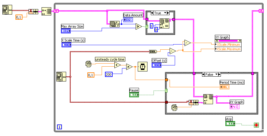
Here is the block diagram of my vi
Hello
Email ID: [email protected]
Try to put two entries in the same loop, to run in the order of wiring.
In addition, you must add a waiting inside the loop (maybe 100 ms) to reduce the rate of update of the VISA application.
A stop button would be nice, too.
The way you wired things upwards, the two loops are trying to write their orders as quickly as possible on the instrument at the same time.
This most likely disrupts the scope.
You're also hogging your processor by not having is not a wait in there.
In addition, you close the VISA reference in two places, not that you would never get there because your curls are endless...
Klaus
-
Detect the change of the value in While loop
Hello
I recently took a code example in examples of using Labview and I'm putting the analog output through my data acquisition card 4461 pxi. I want to have a continuous waveform, but being able to change the volume and the waveform will adjust automatically and be issued through the card.
In the code, I have everything first to open a .wav file and write it. While playing continuously through the while loop, but I want the signal to change automatically when the volume is changed. I know that I should probably use a structure of the event but the while loop, I use to play the signal will never stop unless the user presses stop so it would play permanently in a structure of the event even when the value changes (I tried).
So now I try to see if there is a way to make my time stop loop when the volume value.
You must correct the issues (forget the events if you are not sure of them):
1. If wire you the digital volume to the wall of the while structure, then the whole in structure only tell that one value that happens on the node and will not read new values.
2. to read the new values, move the Volume Terminal inside any building (which will shock your other code that depends on it), or use a local Variable inside any node.
3. to check if the value has changed, you must compare the value to the previous value. To do this, use a shift on the while loop register to store the previous value and then compare it to the new value with the function "not equal?". Wire the Boolean result of this to the conditional Terminal.
A better way for you might be to wrap the multiplication and Analog Write function into the while loop so that you're constantly replaying the waveform and it's continuously being re-scaled by the volume value. This will mean your volume control is being continuously polled (once per waveform playback) and used to scale the waveform each time. You'll need to figure out how to stop, send and play the waveform once per iteration of the while loop by bringing the Stop VI inside too.
-
It is better to define a waveform properties of scale before or after sending new data to the chart?
Hi, I wonder what is the best time to update the properties of the graphic scale waveform.
I'm sampling data every 15 minutes for 192 samples, or 48 hours. I want to draw these samples with x in absolute scale so the scale maximum x is time and x minimum scale at the time mode is x max in less than 48 hours (172800 seconds). I want also to intermediate-scale markers 6 hours apart and to be multiples of 6 hours. for example at 06:00, 12:00, 18:00. It works by using nodes of property but sometimes intermediate markers are on the hour 6 multiple and sometimes they are at 6 hours after the scale min marker. for example, 09:15, 15:15, 21:15. Is there a way to ensure that the intermediate markers are on the hour 6 multiples?
Thank you
Neville
Neville,
I don't think there is a function of the order of execution by using nodes of property information across your graph. If you are concerned about the speed of your VI, I would recommend writing to the property node before update you the chart. I believe that this will ensure that the chart will update only once: when the new data is sent to the curve, as opposed to the update with the new data, then with the new scale.
-
Change the axis label w.r.t. the scale automatically in the waveform graph
Hello
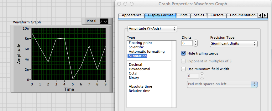
Is it possible to change category axis labels and the value the axis according to the scale automatically? I have a waveform graph which is automatically resized and values on the y-axis of milli, micro and nano volts according to the results of the output from the tests carried out. I need the label of the axis to change automatically according to the scale... Could someone tell me please how to do this. Thanks in advance.
Best regards
Julien
Alain,
I don't know exactly what you want.
If you want to just scale to change as follows: 10n or 5u, use the property format scale IF the Notation.
If you want to change the name of scale label text, you use the YScale.NameLbl.Text property. The attached VI shows one way to do something like that.
Lynn
-
are there different scales of two waveforms of the oscilloscope
Hello
I am writing two waveform on the oscilloscope. But one of the wave are very small scale.
Y at - it any wave of scale are two on the graphical indicator of waveform so that the small signal can have higer resolustion?
Thank you!
Hi tian.
Seek the help of LabVIEW for 'scale double y"...
-
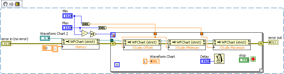
How can I display only a part of the scale in the waveform graph
This is the first time I try to use the waveform graph, since now, I used the table of waveform.
The reason why I moved to the chart, it's that I need cursors.I have 2 problem
the first: in the diagram, the graph moves when I add a new data and the scale of the x-axis stay the same size, in the right size I always saw the new data. How can I do that with waveform graph?
Second: How do I say Labview to the day I click on the graph, I need that because when move graphic I lose the day, and to make I need to zoom out, I drag the imprecateurs.
All this must be done programmatically. The LabVIEW graphic accepts tabular data, not only as the table and the graph doesn't have the ability to retain the previous points, like the story of a graph. You will need to retain previous values and then continually update the graph with the old and new values to get a shift register "chart as behavior. Cursors should be written programmatically re of each iteration, since you rewrite the entire graph.
-
scale of table/chart of waveform
Hello
I have 1 meter construction and I need to scan for electromagnetic fields.
The user has an option to choose the range he wants to scan. That is, he may choose to analyze only the range from 20cm to 50 cm.
I chose to use the waveform table because I need of measures to display 'live '.
So I want to set up X scale from 20 cm to 50 cm only! with the steps that are also chosen by the user.
The problem is that this table of waveform a buffer so that even that if I set up offset and multiply by property nodes as required, it works well for me if I do more than 1 scan (offset and multiply the nodes are defined before each scan.)
What can I do?
Thank you
Would be - this help?
If not, please try to develop. It is sometimes difficult to understand what the problem is is in fact a non-native English speaker

-
adjust the scale of the waveform graph
Hello
I have a graphic wavefrom receives two signals, can I adjust the scale of the y-axis of a signal?
Yes. You create a scale is double and set the plot of the new scale.
-
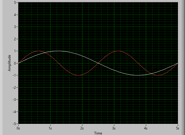
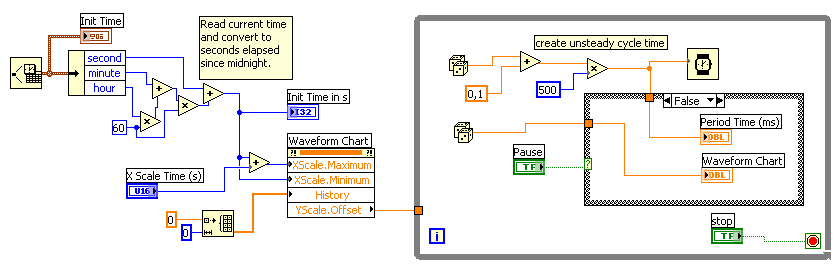
Problem with table of waveform: time scale do not see the time correctly
Hello
I have some problems with a graphic.
I want to display data, and the duration between two unique data can vary. It's something between 50ms and 500 ms.
The problems I have:
1. the time is not correctly displayed in the graph (allways 02:00:10 instead of the current time)
2. the data points in the table have a distance of 1 s (x-scale). This is not correct.I've tried several things, but I thinkt that I am on the wrong track.
Could you please help me?Johannes
LabVIEW 7.1 (!)
I'm sorry. The property on the left node was not necessary...
-
vertical scale 5152, set up the time
I use a pxi-5152 in a pxi-1033 chassis.
I want to play a trick and change the vertical scale between my measurements to increase the dynamic range of a signal that I'm scanning. I made a loop and changed the vertical scale property node after each measurement. It works, but when I timed it the loop, she seems to take 80 ms. I need to do in less than 10 milliseconds.
Is it still possible? I see the real time it takes for the scale change or there at - it something to speed up?
I also have access to a PXI real-time with the same card. Could only accelerate things or is the digitized the limiting on the change of scale factor?
Thanks for any help
-Rich
Hi rich,
I see the real time it takes for the scale change or there at - it something to speed up?
You probably see the effect of the two. There may be something of software that you can do to improve it, but there's always a material limitation when you do this kind of operation. Switching of the means of vertical lines change from one type of mitigation to another path. This means there is sedimentation time involved (electronic and mechanical, with obviously dominant mechanics). The main element in the run-in will probably be the relays that are reversed. There must be a minimum period after the passage of a relay to ensure the data read by the digitizer are correct / valid.
Since you know your signal is going in a direction (descending), then you may be able to improve somewhat by calling the property to write the new range, and then commit node & initiating in a loop which contains a minimum transformation (possibly using queues in LabVIEW to transfer the data in another loop of treatment). If you need treatment in the loop, you must perform the treatment after niScope commit but before launch niScope. This will allow the digitizer begin to settle in the new configuration, and you have to wait less time when you're ready to call to initiate.
I also have access to a PXI real-time with the same card. Could only accelerate things or is the digitized the limiting on the change of scale factor?
Real-time processing ensures determinism, it does not necessarily speed up the application. Determinism and defining a specific priority for calculations of software can help speed upward the software that you are running, the interface of low-level PCI/PXI bus driver with the instrument probably will not change radically. You can certainly try though and let us know what you measure.
I can understand if it is a fundamental issue, because normally people are not change the range of vertical entry on the fly, but if there is a way around it, it will avoid the need for me to put an amplifier with variable gain on the front-end server or buy a digitizer with more bits.
This isn't a perfect suggestion, but just a thought: If you have several scanners at your disposal, you might try setting each to a fixed vertical range and split the signal among them. TClk, you can synchronize these devices together to make sure your data points are sampled at the same time, and then introduce delays in the initial on each digitizer trigger so that they take account of the waveform in a cascade mode. For example,.
Digitizer #1, attached to the greater vertical reach, would have no time limit from the time wherever the trigger is received.
#2 digitizer, set at a smaller vertical range has a fixed period of (10ms?)
Digitizer #3, value the smaller Beach, has a fixed time (20ms?).
Otherwise, if you have assistance with the OR, you could try to call a technical sales engineer to discuss other possible options.
-Andrew
-
NI9225 waveform measurement of network 230VAC
Hi all
I measure the waveform complete (time of the voltage signal) the local power grid with a voltage of 230V L1 - N with a NI9225 module.
Peak values (RMS) 230VAC * 1 414 = 325V pic.I can't to scale greater than + 300V M.A.X parameters entered.
In the statement indicates that the module can measure 240V electric networks.
Can directly measure the shape of wave or shoul, I use a 01:10 for measures voltage divider?
Thanks in advance
Regards Christof
Text of the Manual:
The NI 9225 300 module input analog Vrms C Series has been designed for the waveform of signals measures high voltage. The Vrms 300 range allows line-neutral as a line of measures of electrical of 110 V and grids of the 240 line-neutral networks V. Three NI 9225 channels make the ideal module for a three-phase system. Measures voltage waveform are required to follow events like sag, swell, transient power quality and harmonics. Combine the 9225 OR with the NI 9239 (10 V) and a current transducer to create customizable power quality monitor or a power measurement system.
Die Skalierung as AC measurement wenn ich die richtig Spec understand habe ist.
BIS + / 425VDC ist der range sogar in der Spec angegeben.
Also im bereich messen und deine Wfrms bekommst 300V 240VAC mit schönen Sinus...
No vote was now a screw also as Poweranalyse Schön mitkommt, aber your über etwa 15 Perioden so sicher detection...
10:1 Tastkopf kann nicht schaden, if abgeglichen.
Offenbach... VDE?
-
I'm taking a picture of waveforms and the units of the scale accordingly. I have a picture of the sensitivities that the user can change and do this in my "EUs Scaling" under VI. I would use just of "LAS scale voltage to EU VI LabView", but the sensitivity of my sensors will vary depending on the way through. I can't much the back wave of construction. I think I'm scaling of values of y in my sub VI correctly. The sub VI is inside a loop of acquisition data and after reading MX DAQ. The sub VI is "Scaling had 32ch".
In addition, when you use DAQ MX create channel he wants to channel names to a string of nouns that are delimited by commas. How do I take a string array and comma delimit them into one string?
They are here in 2009.
-
Waveform invalid property value table
I use LV7.0 and you have a problem with access to an array of waveform using a property node. I have a number of nodes of property for the same waveform graph, which I address at the "same time". I use a reference to the chart in knots of generic property. I believe I have 7 lots available on the card, but I address them, between 0 and 6, I get an error of invalid property value (arg 1) on 6. It seems that he does not like me affect the ActYScl 6. When I pull up the properties of the graph, it shows I have 7 available plots. Is there some obscure affecting somewhere that limits the number of plots?... or what is well known that causes this error. Overall the program is quite complex and would take some time to disassemble for display, so I wanted to know if there was anything the hand that can cause this. I have attached a picture of the place of boredom.
Thank you.
You have 7 plots, but you have 7 Y-scales? If you have 2 or more locations that are assigned to the same scale given, so you're probably not as Y-scales that you have drawn.
There is no correlation between the number of sites and the number of scales is. Even the order of the curves according to the scales could be different.
-
Hello
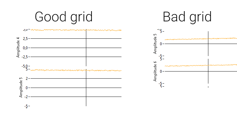
I have a question on the maps of waveform: I made a stacked graph of waveform and I have a weird problem with grids: I each scale ranging from + 5 to-5 and a major increase in 2.5 via a property node (and the minor grid turned transparent). However if it becomes narrowed beyond a certain height, I lose every second increment and the line of the grid, even if I do not change the increment value. It seems that there is a minimal amount of pixel to one grid increment. What is this value? Will there be a chance to continue to move forward on my beginning of mesh? (Because I think that there is still enough room for each major gridlines)
I understand both cultures of images to illustrate my exported graphic problem:
JLP,
By using LabVIEW 2014 I could see the same behavior that you were. It seems that LabVIEW won't ticks if he thinks they are overlapping.
I wasn't able to find the documentation said that directly, but the property to [MarkerValues] node says it will ignore the array if it cannot get values without overlap. You see the same behavior if you increase the size of the text of the increment markers.
To me, it seems that the minimum spacing is set to the size of the text, because if you increase the text size large enough it get rid of line markers, even if your chosen style does not display values (so of course there is no overlap in the text).
Maybe you are looking for
-
Which macbook model is good for daily stock trading?
Which macbook model is good for daily stock trading?
-
Airport Extreme is flashing yellow. Utility shows "Firmware Update" but no button to do so.
Hello my Airport Extreme will blink yellow. Airport utility shows a red circle with a white "1" and "Fimware" available update. But there is no button to update. I can choose 'Ignore' only. AirPort Extreme 802.11n (2. Generation) The Firmware is 7.5.
-
Slatebook x 2-problem of battery alarm and shutdown
Hello, I have Slatebook new x 2 and I have a problem. When the battery becomes low, then I receive an alert and it stops immediately. In fact, it stops and I see the alarm behind the closing down of the dialog window, while it stops. There is no chan
-
try to install 4 GB of ram. Get the error «the file header checksum does not checksum» calculated
Microsoft online tech help recommended I install 4 GB of RAM on my Dell Vista Home computer. The first stick fine boots. When I add the second stick the computer poster "the file may be damaged. The file header checksum does not match to the checksum
-
Error 0 x 80010108 photo library
Original title: probably the virus? c:\windows\TEMP\nsz3AFF.tmp specified in the Inbox start is not valid... have also staple of my icons opening error 0 x 80010108 photo library