scale of table/chart of waveform
Hello
I have 1 meter construction and I need to scan for electromagnetic fields.
The user has an option to choose the range he wants to scan. That is, he may choose to analyze only the range from 20cm to 50 cm.
I chose to use the waveform table because I need of measures to display 'live '.
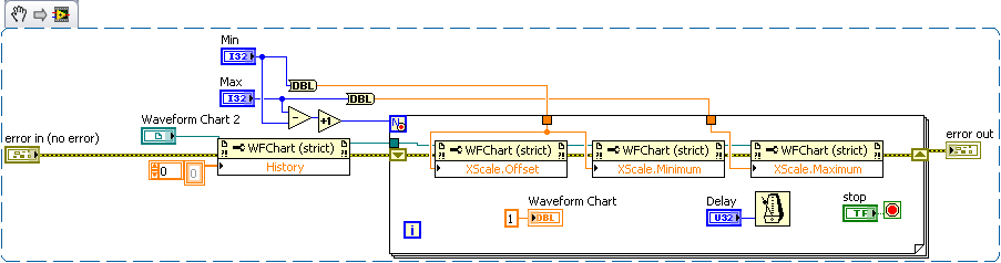
So I want to set up X scale from 20 cm to 50 cm only! with the steps that are also chosen by the user.
The problem is that this table of waveform a buffer so that even that if I set up offset and multiply by property nodes as required, it works well for me if I do more than 1 scan (offset and multiply the nodes are defined before each scan.)
What can I do?
Thank you
Would be - this help?
If not, please try to develop. It is sometimes difficult to understand what the problem is is in fact a non-native English speaker
Tags: NI Software
Similar Questions
-
What would be the best type of table/chart to use?
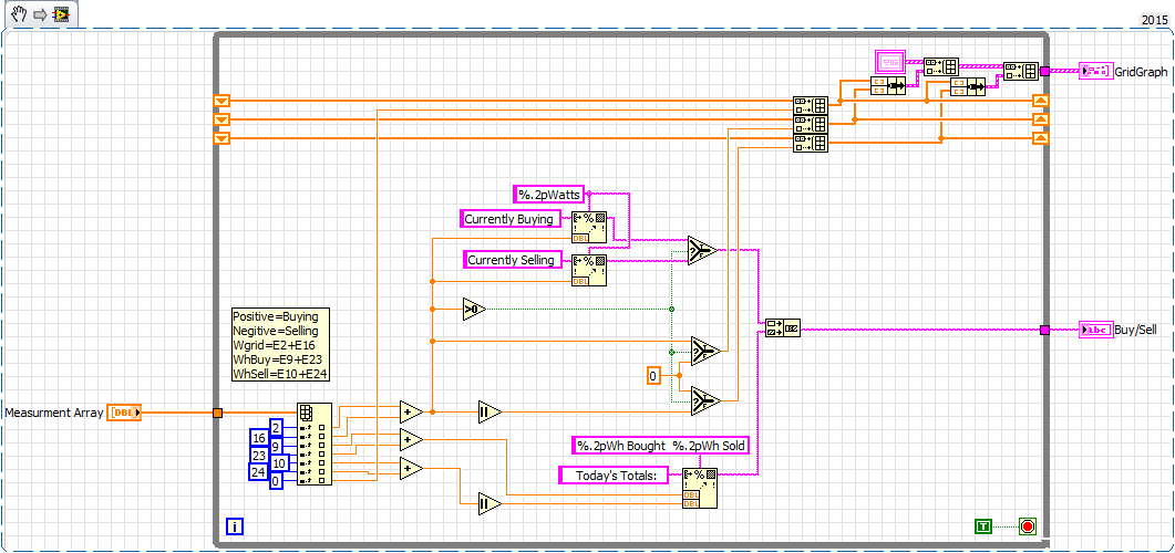
I'm testing a grid tie inverter. To the side of the grid, I need to provide a table/chart, which has:
X axis: fixed, from 00:00 (midnight) and ending at 23:59
Y axis: last watts measurment purchase / sale
The table/graph must be emptied at midnight every night
Measurements are performed at intervals of 10 seconds.
This program will be running continuously for long periods of time (months in a row)
I'm leaning towards a xy chart because the program can be started and stopped at any time and it's the only way I can think of to make sure that the line of measurnents correctly on the X axis.
But I'm afraid that, since all XY graph is held in RAM (each line has its own displacement register) and measurment taken at intervals of 10 seconds.
Who's going to add up quickly as the days go by finally out of memory and crash.
Also I can not know how to delete the chart every day to avoid said memory leak.
To make matters worse I need also a same table/chart for the release of load, batteries and solar panels.
Here is my grid purchase sub - vi that I call after each action is taken and a message of State output and graphics for the main program.
RavensFan wrote:
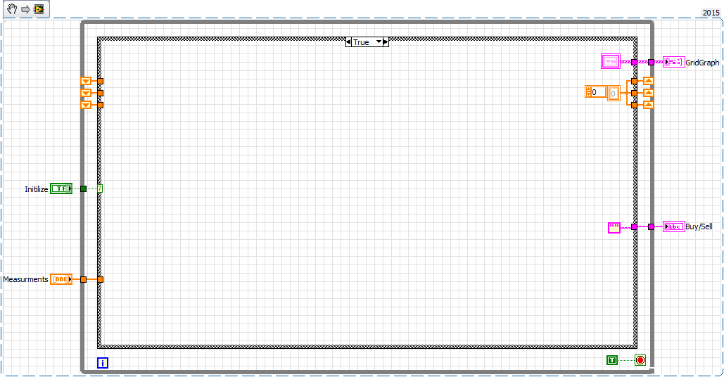
I would follow the advice of Lynn and manage each day of data as a separate table of data. So do not grow a value of several days of data in a single table. Move to another storage such as file system and clear the table and start again at midnight.
But I think what they XY graph is the best display for all the reasons you listed as discontinuous data.
Yes I'm still with the XY graph as we are still in the first part of the development lifecycle and it is possible that the device could be stopped and started several times during the day and I don't want the graphics to get all out of whack.
But looking at my sub - vi, it occurred to me to treat it as an engine of the action or functional global and put an initialization state it I can call at midnight to clear the shift registers.
For what is to come back a day or more, maybe it's something that I have work later. Daily data are saved locally in a separate file and using the XLR8 tool I'll roll seven daily files in a weekly Excel workbook for later analysis.
-
Read file measure to XY Chart of waveform
Something pretty simple that gives me a hell of a time right now.
I have a .lvm here who was rescued from an acquisition of data and has a column of numbers from 0.0000 - 27.0000 to very small no. The next column is the amplitude of the signal at the point. Now this file LVM I'm starting a new vi and I want to read those values x and Y and get them on a waveform graph. Now, I tried hanging 'Reading a file measure' and tried to "Build the Table", but who do not want to connect on a chart. Rather the file directly on a chart causes two very different lines is displayed but is no where near what I'm looking for.
Some tips on how to complete it?
Tasty,.
More often than otherwise, I find screw Express to be more trouble than they are worth. Here is an example of reading data tab delimited in a .txt and tracing the values of are against X a value on a chart. It will be useful.
Andrew
-
1 table D of waveform DBL file or its
Hello.
I am building an application where I have an accelerometer with an interface USB-1208FS samples.
I have this loop on the inside with a few virtual instruments to display the waveform and frequency of it components. I tried many different approaches to record in a file, but it doesn't seem to work. No file is created even although I am administrator.
Data that are fed to the filters and these great are "table 1 d of waveform (DBL). Tried to convert other types of data, but does not work. This VI for example 'write waveform of File.VI' does nothing even if it should accept this type of data. It's "waveform table is a 1 d table the you want to write to a file of wave forms.»
I'd appreciate any help on my way to accomplish this task. With regard to Abraham
You still have not posted this VI. You say exactly what function and it is inside the loop / out of the loop that wants to say? My only guess is that you use the button stop in the toolbar.
-
Conflict table chart control reference
My vi has 6 graphics, and I need to change them through nodes of property through on my vi, then I wanted to store all references to graph in an array and pass it. When I do that, I'm a class conflict between my entry table and a table in the cluster. They are two waveform signals Refnum (strict), so I don't know why there is a conflict. See the attachment for more info.
I will usually use a group instead of a table so that I can access all the properties, but in your case...
Unplug the broken wire, create an indicator of the output of the generation of table.
Copy it and go back and change your type def and replace the stone with your new version. He should associate after that.
Note:
In your Subvi (if you stik with the table) you may need to perform the wire (more specific) class get the properties you need.
Ben
-
Drawn 2 data 2 the value axis on the chart of waveform
is it possible to put 2 y-axis on a waveform graph?
1 left and the other more appropriate?
as I have 2 data sets, A and B.
I would like that my data is plotted using the left side of the y-axis which is 0.5 to 5
B data on the right side of the axis y from-25 to 105
the two using the same x-axis
I have all the data I need, but now I can only understand 1 tracing of data but not the other I need to be together in 1 graphic data of the two.
any idea?
Hi number,.
did you read what I wrote?
Right-click on the scale of it, select "double ladder". Right-click the scale newly created, select "Swap" side Right-click the properties of the plot in the legend of the plot and select 'Scale Y'-> 1 scale!
-
Field of table to the waveform graph
Hi, I have a table I want it draw in a waveform graph. I tried to experiment with the wave function of building and others, but could not get anything out of it. And how to choose which points I would like to draw on the graph?
Thanks in advance.
You have only wired 2 signals, so just the two signals. If you need more, expand the node for merger signals and cable signals more to it.
5 and 6 are the numbers in column for Poly_M_Tem & TF_M_Temp, I had to delete the first column, as was the timestamps, and it was not necessary. It is so different from your 6 & 7.
Hope that makes sense.
-
Excel in Indesign Table chart?
I can import a MS excel chart in a table in Indesign? And how do I do it?
Hi Pudgesan,
You can paste data from an Excel worksheet into an InDesign document or document. The Clipboard handling preference settings determine how text pasted from another application is formatted.
If the text is selected, the information in the form of tabulated text unformatted, which you can then convert to a table.
If All the Information is selected, the pasted text appears in a formatted table.
If you want more control over the formatting of the imported table, or if you want to keep the formatting of the spreadsheet, use the import command to import the table. If you want to keep a link to the spreadsheet, select Create links when placing and spreadsheet text files in the file management preferences.
I hope this helps.
Kind regards
Sumit Singh
-
Variation of the data in the areas and tables charts
Hi all
I was creating an RTF model. The actual data were a kind of form below:
A1 - 37.70%
A2 - 10.18%
A3 - 50,76%
Data above has been shown very well in the table but on list variants have been found. I simply created a pie chart, but I found something strange while previewing [even in the actual final PDF report also]. It showed the values in the following graph if the original values were something else.
A1 to 38.22%
A2 like 10.32%
A3 51,46%
Can anyone tell why such a variation is there in the graphics? Therefore, different values of the original in graphics? How can this situation be avoided? What property must be defined for the chart so that it accepts only original values even as shown in the tables?
Thank you!It should not and is not any change in sum :),
unless you have done differently in both entities (report and graph) -
Clickable bar or data tables charts
Hello
I displays a chart and a table of data for an account of some statutes. : Example A 10, B status: situation C, 30: 40.
I would like to know if there is a way to make these graphics to bars or data table lines clikable, so I can go down in the State to get detailed information. Example, by clicking on the status bar or line in the data table, I would like to redirect to another page where I can show more details such as all users who belong to State A, etc.
Please suggest.
Thank you
PradeepHello
For a chart, you need to include a link rather than the null link. For example
select
'f?p=&APP_ID.:21:'||:app_session||'::::P21_DB,P21_SCHEMA:'||OEU_ID||','||OET_TBL_OWN_NM||':' link,
"OEU_ID"|| '-' ||"OET_TBL_OWN_NM"  label,
COUNT("OEU_ID") value1
 from "IBU_DBRTUT01"
APP_ID.:21 means that he runs on page 21
P21_DB, P21_SCHEMA are hidden on this page elements that store values (you need to create your own)
*|| OEU_ID | «, » || OET_TBL_OWN_NM | * the values from the graphPaste the part of link in your series and then just edit these pieces. Then you must create items hidden on the page you want and do a query on this reference page the items hidden in a where clause clause
For an interactive report you click a column (in the attributes report) attributes, and then pass the "links" section by passing values for the items you want.
Mike
Published by: Gerd on October 21, 2009 10:08
-
Save the table/chart as an image file
Hi all
I wonder if there is any way I can save the graph Microsoft graph/with the data as an image file (jpg, etc.)? I need the image on the same file saved under the Microsoft Graph graph/so that the program is running. She should have black and non-white colors.
I knew how to do it in matlab but don't know how to do it in labview. Can someone help me with an example Vi that can do it in labview 2009?
Thank you!
It's pretty easy. Just create the image for the chart and use one of the screws the graphic format:
Note: This is also explained in the Help of LabVIEW.
-
I have a VI that creates. CSV files by taking measures so that I can analyze the data in other software. I recently added a camera to my system which also creates one. AVI file I want to analyze together with the. Data in the CSV file.
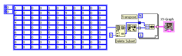
I would write a VI that opens the. CSV file, and then display this data as a diagram, so that finally, I can use a cursor to display the correct view of the. AVI file. However, I can't figure out how to do this. When the. CSV file is opened it creates a 2D array, the first column is the duration in seconds. I want it to form the X axis. 4 other columns in the table are different transducers voltage values ranging from - 5v to 5v, these values would be given amplitude on the axis Y.
If I understand correctly, I can use an XY graph for this; However I have not had much chance to find how to do this and the included examples are not exactly a lot less explaining how to do this kind of thing.
Hello!
I used the node "remove table".
I delete the first column (over time) and send the time lost in the loop (not indexed) column.
It contains the x values of our data set.
The rest of the table gets transposed (I forgot about it before, I was too hasty).
Each column is now a line, get indexed by the loop and is clustered with the values of time to a pair of values x and y.
And in fact.
I recorded as 8.5 VI.
Welcomes the CR
-
different image to display for a range of values in the table of specific waveform
Hello!
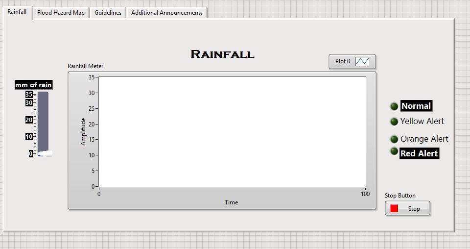
I'm a VI that is as a precipitation meter reader that displays a picture of what will happen with a place with this amount of rain and display a message (which appears on the channel). Here is a picture of the public Service.
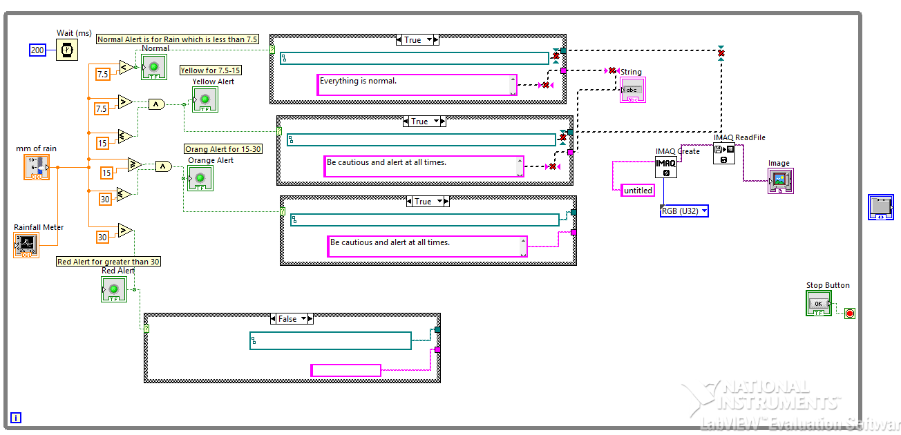
The mm of rain check will be the entry and it will be displayed in the graph. Boolean controls on the other side lights depends on the value of the entry. What I want to do is I want to display an image (which appears on the tab map of flood hazard) and a sentence on a string (which will appear on the additional announcement tab) for each Boolean control. The images and the sentence on the string is different for each Boolean control. For example, if the input is of 7.5, the Normal warning light comes on and at the same time, I want to display an image and a message on a channel. Here is the BD.
I can't launch the VI because there is more than one source in the chain and in the part of path. Also, I don't know what I will in the false statement in the Structure box. Also, I don't really know if putting the box Structure for each a reason.
Help is really appreciated (because that's my problem for almost 2 weeks now). Thank you very much.
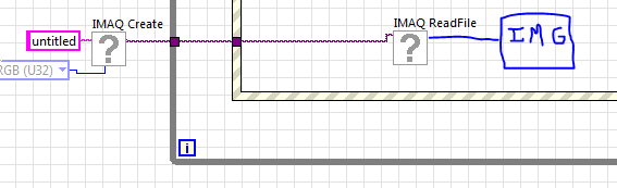
I do not have the Toolbox, but I think all you need to do and put the right photo (or just make you a selector of images, such as a table that you can find in the functions of the vision).
-
Pivot table dynamic table - chart axis of the show as "percent".
Hi all
I have a pivot table is generated, with the lines as year/month and columns like web browser. However I only watch 5 albums used, browsers so that used columns are dynamic.
I would like to show the graph as a 'percentage of line. I know that I can turn this on the data in the table, but it does not filter although in the graph. Does anyone know how to get there? Can you add the total of a line and use it in a formula?
Thanks in advanceHello
Not sure how the PivotTable, however we have may be able to pull this back as a separate column in the criteria tab which you can then use.
What is your metric name?Lets say you have Time.YearMonth, browser, count
Add another column, change the fx for this column and use sum (time.yearmonth County) - this will give you the total amount for the year regardless of browser.
Add another column and simply count / sum (time.yearmonth County) * 100 to get the percentage of the total for the year - plays about with using them in the pivot or you might get away with a straight table view?Hope this helps, another solution would be to implement a shaved basic measure to the RPD.
Published by: Alastair_PeakIndicators on March 31, 2010 08:26
-
How to adjust the scale of a chart using reference points?
Hello
I'm working on little code to display data from a spectrometer. I've got to the point of producing a graphic intensity vs energy, but I'm having some trouble of calibration of the x-axis (energy).
The customer wants to be able to insert filters with a cutoff of known energy and use those points to determine which positions on the graph correspond to what energies. In terms of programming, I need to let the user click on the graph at two points with known values and use these points to recalculate the XScale multiplier and offset (I think).
I tried a few different things and attached by the best attempt so far. This is a simplified example, but I hope it picks up enough problems to be useful. I can't help thinking there must be an easier way to do it. Any suggestions?
What you have done is good. The only thing that I would have a little problem is that there is no visual feedback on the graph for the user. You can also do this with the sliders. Let them drag the sliders on two points. It is more Visual, and you can see where you have selected. I'm not sure that it will be much easier than what you've done. You could also use a hybrid of the two methods and have the cursor to move until you have selected.
Maybe you are looking for
-
Formatting external to PC - transfer files
Hi all I need to transfer on 36gigs (Quick Time) videos to a PC user. How to format the external hard drive that I will give them after transferring the images of my iMac (10.10)? Thank you Al
-
I forgot my password, simple pass does not read my finger
I can not connect. I don't remember my password, I can't use a simple pass.
-
First of all, the so-called help format is not very friendly. (Lost) took a half-hour just to get here.A new version of adobe acrobat reader has been published recently.1. whenever I open a file, some thing open on the right side, I have no use for
-
InDesign CS6: moving pages to another doc creates a megaspread
Hi friends,I'm trying to merge several documents into one at my workplace in Indesign CS6. In the script first I ask the user to select the docs to merge, what am I saying to Indesign to open all documents selected one by one and duplicate pages in t
-
Inadmissible graduated filter in Lightroom 5
The graduated filter does not work correctly. I can access it, load the information I want on the filter, and as soon as I place the + sign on the image, it will activate. completely non-functional at this point. I chose different images, and the r