SDO_LENGTH, FROM_WKTGEOMETRY and geodetic coordinates
I'm confused by the results I get from the function of the SDO_LENGTH() geometry. I have a line described in WGS84 coordinates as string WKT. I run the following query:SELECT SDO_GEOM. () SDO_LENGTH
SDO_UTIL. FROM_WKTGEOMETRY ('LINESTRING (-101.782447 48.339560,-101.210446 48.058227)');
0.05,
NULL,
NULL VALUE
)
OF THE DOUBLE
The result I get is:
0.63744286088245
However, the two coordinates in the line are remote in reality about 52.7 KM.
I do not specify the UNIT parameter to the SDO_LENGTH function, and The Oracle Spatial reference manual says the following:
"If this parameter is not specified, the unit of measure associated with the data is assumed. For geodetic data, the default unit is meters. »
Link: [http://download.oracle.com/docs/cd/B10501_01/appdev.920/a96630/sdo_objgeom.htm#i856257]
I find no conclusive documentation to tell me one way or another, so I'm assuming that FROM_WKTGEOMETRY() assumes that the coordinates in my string WKT are geodesics. Because I guess I start with a geodetic geometry, and do not specify units for SDO_LENGTH(), I should get the length of this line (ie. the distance between two coordinates) in meters.
One of these assumptions seems to be incorrect. I have the idea that I need to take additional steps when I convert the WKT geometry (such as specifying a SRID), but I can't determine exactly what I need to do.
I would be very grateful for any advice.
Thank you very much.
with the means of data: it can be derived the SRID that is associated with the geometry.
as WKT does not contain an SRID, the sdo_length function does not know which units can be assumed, or don't function knows that stop coordinates.
For this purpose, you must use the constructor with WKT SDO_GEOMETRY and providing an SRID. (read http://download.oracle.com/docs/html/B14255_01/sdo_objrelschema.htm#CBBFGHAE)
SDO_GEOMETRY ('LINESTRING (-101.782447 48.339560,-101.210446 48.058227)', 8307)
Since you're passing the srid and the wkt, the returned geometry has a valid SRID which should solve your problem.
SELECT SDO_GEOM. () SDO_LENGTH
SDO_GEOMETRY ('LINESTRING (-101.782447 48.339560,-101.210446 48.058227)', 8307).
0.05
)
OF THE DOUBLE
Returns 52788.7151886496
Luke
Published by: lucvanlinden on October 9, 2008 21:28
Tags: Database
Similar Questions
-
Drag and drop coordinates and put back
Hello
I am developing an application of slide / move. I found a very good example of Gregory Lafrance in the cookbook to work from. http://cookbooks.adobe.com/post_Simple_example_of_using_a_container_as_a_drag_and-16272.ht ml.
I want to keep the coordinates of the images when they are deposited to the target in a table. In addition, let the user repositioning (drag) the image that is already on the target area. If an image is repositioned, and then update the coordinates.I'm looking for advice on how to solve this problem. How I would get the image data once it has been copied and moved to the target area? I appreciate any information you can give me on this topic.
Thank you!
Hello
You need not really store contact information, a way to 'drop' on a target is to create truly a 'keeper' this passer-by holder has an image inside and the holder can also do things like moving around the drop target, because you create these holders, you can store them in a table so that you have a list of DEA escaped objects also you can browse the list and get coordinates etc.
http://gumbo.flashhub.net/pagedrop/ - source included
This example creates a container for the deleted image that allows you to manipulate the size of rotation and the position of the picture dropped, load some images drag an image on the main application and see what happens when you go over it.
David
-
Reg: The Latitude and Logitude coordinates
Hi all
I am new to Oracle optional, I of coordinates of latitude and logitude information in the following format 0217.21.09S 145.30.36W.
If these data are supported in the SDO_GEOMETRY object.
If not, how do I convert it to the format of SDO_GEOMETRY (X, Y) coordinates.
Thank you
VinoYou need convert these coordinates in decimal values before that you can store in the SDO_GEOMETRY objects.
You can check this site for more information about how to perform this conversion: http://www.soda-is.com/eng/overview/convert2decimal.html
Note that Oracle Spatial requires data in the form X = longitude and Y = latitude.
Siva -
Hello
I'm working on a project that will require projected and geographical coordinates for different in product files. I have no problem, define, store, extract or corresponding point coordinates. My columns for these coordinates with the SRID 8307 are defined in user_sdo_geom_metadata table as follows:
INSERT INTO
USER_SDO_GEOM_METADATA (TABLE_NAME, COLUMN_NAME, DIMINFO, SRID)
VALUES
('INVENTORYGEOMETRY', 'INVGEO', MDSYS. SDO_DIM_ARRAY (MDSYS. SDO_DIM_ELEMENT ('Longitude',-180, 180,.05), MDSYS. SDO_DIM_ELEMENT('Latitude',-90, 90,.05)), 8307);
the index:
creating index 'MYDB '. "' INVGEO_IDX ' on 'MYDB '. "INVENTORYGEOMETRY"("INVGEO") indextype is MDSYS. SPATIAL_INDEX;
However, I'm confused as to how I'm going to have a column that has both geographic and coordinated projected. Am I allowed to set longer SDO_DIM_ELEMENT (s) FRO the SDO_DIM_ARRAY with min/max different values. For example, I'd be able to always use an SRID of 8307 times WGS 84 and data GRS80 (ellipsoid), something like the following:
INSERT INTO
USER_SDO_GEOM_METADATA (TABLE_NAME, COLUMN_NAME, DIMINFO, SRID)
VALUES
('INVENTORYGEOMETRY', 'INVGEO', MDSYS. SDO_DIM_ARRAY (MDSYS. SDO_DIM_ELEMENT ('Longitude',-180, 180,.05), MDSYS. SDO_DIM_ELEMENT ("' North latitude-90, 90,.05").
(MDSYS. SDO_DIM_ELEMENT('FIXEDGRID_.5Resolution', 0, 26916,.5)), 8307);
Is that possible or do I have to create a new column in the database?
In addition, I don't know the relationship between the SDO_ELLIPSOIDS and SDO_GEOMETRY tables. You you please explain it to me?
Thank you for any help you can give. I'm confused as to how I'm going to make this work for both geographic and projected coordinates, or if I'll be able to make it work.
Thank you
EricaErica,
You have geodetic and projected data in a single column of a table BUT you cannot index in space because the index does not work on the two projections.
You have, says Bryan, create two columns:
create table INVENTORYGEOMETRY (
  fid integer,
  INVGEO sdo_geometry, /* For the geodetic data */
  INVPROJ sdo_geometry /* for the projected data */
);
If you do this, you must create two user_sdo_geom_metadata entries. As you have already done and one for projected data:
INSERT INTO
 USER_SDO_GEOM_METADATA (TABLE_NAME, COLUMN_NAME, DIMINFO, SRID)
 VALUES ('INVENTORYGEOMETRY','INVPROJ',
 MDSYS.SDO_DIM_ARRAY(MDSYS.SDO_DIM_ELEMENT('X',0,1000, .05),MDSYS.SDO_DIM_ELEMENT('Y',0,1000, .05)),XXXXX);
Where you replace 0,1000 ranges with your actual data range and XXXXX by your actual SRID projected (for example, 28355 as in the example below).
Now, assuming that this table Gets the INVGEO column populated first (by some external dynamic flow) you could synchronize the column projected via a trigger as follows:
create trigger inventorygeometry_proj_bi
before insert
on inventorygeometry
FOR EACH ROW
begin
   if (:new.invgeo is not null) then
     :new.invproj := mdsys.sdo_cs.transform(:new.invgeo,28355);
   end if;
end;
/
Finally...
In addition, I don't know the relationship between the SDO_ELLIPSOIDS and SDO_GEOMETRY tables. You you please explain it to me?
The SDO_ELLIPSOIDS table is part of the implementation of the projections in the package Oracle Spatial. When you use a SRID in a SDO_GEOMETRY, Oracle uses the SRID to interrogate the underlying tables (which SDO_ELLIPSOIDS is only one member) to get the properties of the projection for example the definition of the ellipsoid being a.
I hope this helps at all.
Don't forget to assign the points you like if our responses are considered correct or useful.
concerning
Simon -
SDO_NN and SDO_WITHIN_DISTANCE return distance on road or on the straight line?
Hi all,
I want to ask if the distance between 2 points calculated with SDO_NN and SDO_WITHIN_DISTANCE is a distance on the road that connects these two points (for example 35 miles) or is a distance in a straight line that connects these two points (for example 20 miles)?
Thank you very much.The distance is the same that you use the sdo_geom.sdo_distance function. This is the minimum distance between these two geometry objects. Wouldn't be a straight line for (circle distance) geodetic coordinate systems.
Jack
-
Geodetic data in the International Dateline
Hello
Am I right in thinking that there is currently no way to build and use geodetic, put data except the geometries of query MBR, who cross the international dateline, + or - 180 degrees longitude?
I see releases of some older posts suggesting that this could be possible in the future, and I have had success with the help of MBRs shown here geodesics, as:
http://download.Oracle.com/docs/HTML/B14255_01/sdo_cs_concepts.htm#sthref556
Unfortunately a MBR is problematic in the case of an area of interest which is quite large and defined in projected coordinates, for example a planned rectangle defined in the four corners that covers roughly the American State of Alaska. Distortion is so large (the thing is more like a sinuous trapeze on the globe), when converting to a GEODESIC MBR, MBR resulting covers the part of the area of continental of the United States, but not all of the State of Alaska.
I want to be able to do is to add shapepoints along the projected rectangle, covering the international dateline and use this form as a geometry of the query.
Thanks for the tips!
MattAll SDO_GEOMETRY based on a geodetic coordinate system that can cover the dateline (since 9i). There is no limitation or restriction for operators or functions. The GEODESIC optimized rectangle was introduced to help users who wanted "rectangles" based on an equidistant cylindrical projection, such as the limit of Northern and southern of the object coincide with the Parallels of latitude.
You will be free to densify the borders of your rectangle in any projected space and transform the result in geodetic longitude and latitude. You can use the resulting geometry for any query without restriction, either that she crosses the dateline (covers a pole) or not.
-
XYZ coordinates with matrices?
I'm doing a trace of contours. Currently I have three tables 1 d containing x, y and z coordinates. Contour 3D of VI in labview option requires an x, y and z of the matrix, every 2D. I don't know how to do in this regard. Thank you.
-
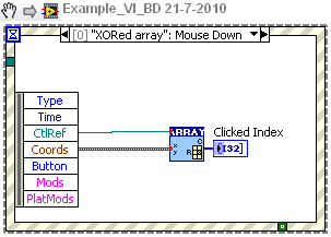
Coordinates of the elements in the array
Hello
I'm playing with mouse click coordinates, especially because his Friday afternoon , but also because it might be useful
In the attached code, I want to click on one of the channels of my table control and what element of the array corresponds to (which later will be used to draw the other pieces of the code based on the content of table)
I can use the position of the table and the coordinates of the mouse and everything works fine.
BUT... only if I select the zero element until I run the code. If I select another element, then run the code, I get wrong results.-Are there a way to get the coordinates of the element zero of my table regardless of what the user has done?
I can think of workarounds using the coordinates of the control table (rather than details of the chain), but it is affected by the label size/visibility control feels so less reliable.
Using version 8.5.
Thank you
IanThere is a utility VI of the repository of LAVA located here.
Dealing with this problem:
Tone
-
VBAI: Problem of coordinate reference system
In a stage of my VB AI application, I'm set a mark at the center of a circular object correctly. In the next step, I do a 'find circular edge', including the "Reposition region of interest" value to a coordinate system.
However, when the object is moving, and the coordinate system with it, find a circular RIM does not follow this coordinate system, but rather remains fixed in space.
What should I do to have find a circular rim move with the coordinate system?
Make sure that when you set up the step of the coordinate system, you put up-to-date in the X direction and Y. By default it puts just updated in the X direction, and even if the overlay appears updated in both directions, this can be misleading. If this isn't the problem, you can include a simple inspection with some images to illustrate how you got in this State.
Thank you
Brad
-
GPS coordinates of pictures is not displayed
Right click on the thumbnails of the pictures and selecting Properties > details does not display GPS coordinates of the photos. Not only the data, but the data field itself. And that's for each photo, even those taken on my own phone with the settings > system > location set in place, as well as photos taken with several of my friends phones. And the coordinates are displayed in Picassa, either. Why are they not the GPS coordinates showing, and how can I make them display?
You should look on your phone (if it's Android) and see if under settings > location you have "Tag Photos or videos with location" lit. The only reason the GPS coordinates show is if the data is not present in the image file. This seems to be the case with you, like Windows or Picasa is to see GPS information in the metadata.
-
How to get the coordinates of the screen when they are hit.
Hi all!
I am a beginner on the development of blackberry, also a beginner in programming in general ^^
I've done some app using just QML and take some C++ tutorials
I try to get the coordinate of the screen when the user touches, I wasn't able to do that you use just QML, I found the source TouchEvent and tried to make it work on C++, to get the windowX and windowY coordinates of the touch.
http://developer.BlackBerry.com/Cascades/reference/bb__cascades__touchevent.html
I use the image on background to try to get contact with the event.
So far, we have:PPS:
class LostInSpace : public QObject { Q_OBJECT public: LostInSpace(bb::cascades::Application *app); virtual ~LostInSpace() {} public slots: Q_INVOKABLE float screentouchY(bb::cascades::TouchEvent* event); Q_INVOKABLE float screentouchX(bb::cascades::TouchEvent* event); private: QPointerCPP:
LostInSpace::LostInSpace(bb::cascades::Application *app) { QmlDocument *qml = QmlDocument::create("asset:///main.qml").parent(this); qml->setContextProperty("app", this); AbstractPane *root = qml->createRootObject(); app->setScene(root); fundo = root->findChild QML: (I'll do later animations, it's just to see if it works. I mean a "unknown simbol app" the Notecard, I thought I just had to put "qml-> setContextProperty ("app", this); in the constructor)
ImageView {
                objectName: "fundo"
                imageSource: "images/fundo1.png"
                touchPropagationMode: TouchPropagationMode.Full
                onTouch: {
                    tiro.translationX = app.screentouchX();
                    tiro.translationY = app.screentouchY();
                }
            }
Any help will be very appreciated!
Thank you!
Hey there,
You don't need to do... You can access the 'event' TouchEvent object in the notecard: {} area QML...
ImageView { objectName: "fundo" imageSource: "images/fundo1.png" touchPropagationMode: TouchPropagationMode.Full onTouch: { tiro.translationX = event.windowX tiro.translationY = event.windowY } } -
How can I remove the GPS coordinates of my Hi Res images ONLY WITHOUT 'Save four Web' or Lightroom
Hello
I take hi res photos of wild animals, rare and plant at the same time my camera and deliberately ACTIVE GPS iPhone. Use the photos and GPS coordinates to document and draw my remarks with the dates on the cards. CANNOT disclose these sites to third parties. I don't want to keep metadata in my photos to the end.
Using Photohop extended CS 6 MAC. Save files to the hi res TIFF or PSD and sometimes electronic-mail/download my pictures on the web when I am done.
- I can't use 'Save for Web' delete my metadata - I don't want a compression in jpeg format. Need to preserve color profiles.
- Don't have Lightroom.
How to use Photoshop for remove ONLY the GPS coordinates of my hi res images data EXIF? You want to keep the other EXIF data.
Surely Adobe can provide this service to rescue?
Thank you
Yes, as others have mentioned, just use the bridge and remove the entries here. You can select an entire batch of files and have them all at once.

-
Hey all,.
Recently, I have a project that invovles attempt automatically images of 'Mock-up' with a standard logo. For example, I have 1000 images of products, and I have a picture of the logo which must be placed (over-buried) on top of each image. I know I can do this with the imageOverLay() ColdFusion function. However, I guess that it always puts the overlay image in the middle of the underlying image (assuming that they have the same width and height settings). I was wondering if there was any possible way to specify and X / coordinate of the upper-left corner of the overlay image and have the overlay image placed in that location?
An example of a site:
http://www.internalsearch.expandedproductsearch.com/catalog/48/
You will notice that all products have an image correctly placed on the products. And I can assure you that this was not done by hand. They must have a way to specify where the image of recovery should go for each product, and then it automatically overlay (logo) image at this location. Can anyone think of any other way to do it?
Any information would be greatly appreciated!
You will want to use the ImagePaste function which allows you to specify an x, position y place the logo: http://cfdocs.org/imagepaste
-
Coordinates of the anchor point
A new user of InDesign (CS5) with a basic question (maybe).
I have an object, say a box with a.5 pt line. I select by using the selection tool and the coordinates are given as 1 in x:, y: 1 in. Now, I select the point to upper left corner using the direct Selection tool. I guess that the coordinates of this point should be the same. But instead I x: y: 1,0035 po 1,0035 po.
Why is this? Also, is there a way to do the same thing?
This has to do with the way the features are taken into account in the width of the object. By default, the lines are centered around the frame of the object. With a race .5pt, .25pts of it extend from each side of the frame.

You can change so that the box is exactly 1 by 1 in if you have the time to harmonize with the Interior however:

-
Missing in Control Panel model wired adjusters and position
OK, I'm sure it's a fundamental issue, but suddenly when I select a layer in the timeline panel, or even that there position the property, it accentuates not wireframe outline of the layer in the comp Panel. In addition, the position adjustment knobs (arrows in red, green, and blue that adjust the x, y and z coordinates) are not visible and missing.
I tried to restart After Effects with Ctrl + alt + shift to delete the preferences of the user and always the same behavior. I think it might be a problem with a preview mode, but I couldn't the various attempts to not work.
Someone knows the probably simple solution to this problem?
-denez
Go to the menu, and then select view > layer controls
You must press Shift + Ctrl / Cmnd + H sometimes.
You can also get to the controls by selecting the Display Options in the little menu in the upper right of the Composition Panel.


Maybe you are looking for
-
I tried to play videos on my Pavilion 23 Office all-in-one running Windows 8 and nothing happens. What are the steps to fix thios dilemma? Please
-
Maximum frequency of outputs digital
Hello I use a NI USB 6218 BNC camera. I try to turn on/off the digital IOs hoping to get a frequency of 1 MHz. However I'm unable to get more than 600 Hz. Should it? Is there a way to get a faster frequency? I tried programming in LabVIEW and C++ (bo
-
I wish to fill a table with data recevied the dequeue operation. Here's what's happening at the minute... Connecting the array function to build the corresponding element rewrites table for each wait operation leaving me with an array of 1 element, t
-
Error 1606 when trying to install open office.
Already tried to fix it on the support web site. Wizard completed successfully & restarted the computer. Still did not work. Still getting Error 1606.
-
Hello I'm trying to set up an existing web application on Vista (IIS7.0). The application was built using VS 2003,.NetFramework1.1 with Enterprise Library 1.1 When I try to run the application on Vista, I get the following error: Description: An unha