Simple 20 s delay
Hello, I am brand new here. You want to create a very simple program. Press a button-> start a 20 sec timer-> LED lights up. Can someone tell me how to do this?
Thanks in advance.
~ Pierre
Have you read the post completely? I gave the "TIMER will BLINK" function as a suggestion. This will allow you to do other tasks inbetween 20s and in the end, it will give high-boolean. Wait FOR ms is here, but you will not be able to access the Panel of Frontt for 20 seconds more.
Tags: NI Software
Similar Questions
-
RIO crashes when you use tcp communication and web server
Hello
my controller cRIO crashes after a short time (usually less than a minute), when I use simultaneously to the web server (to interact with a remote control) and make some tcp communication (using STM 2.0 library) for data logging. Is it a problem of overall performance of the controller, or a problem of band network bandwidth (I'm happy to send some values every 100ms), or a programming problem; in the latter case, what should I do to make the system more stable?
Kind regards
PS: I use a cRIO 9022 with LV 2009f2 + RT and NOR-RIO 3.3.0
Hello
You can try with a simple while loop + delay instead of loop timed for TCP communication loop.
Concerning
-
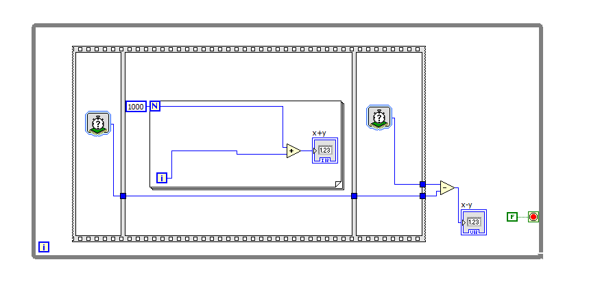
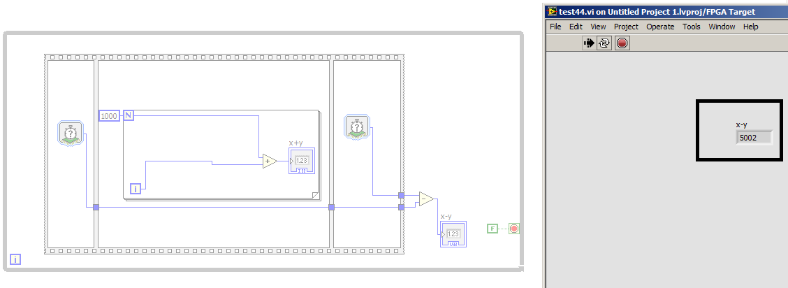
example simple + huge delay + fpga
Hi Member
I'm trying to caclute number of clock for this example caculate, the delay for the ' ' «for loops with 1000 run»»»
After complition process the vi was executed on fpga and read the number of cycles in the pc with the real time and the number of clock was 5002 clock as shown below
What is c?
is their any wrongdoing in my vi
mangood wrote:
So if a system (add many components, sub) and put this system inside the ""while loop"
Inverse of the period of the loop will be the frequency of the loop. Or frequency system is true!
-----------------------------------------------
I'm sorry for the stupid question, but my work on the architecture of the systems so these parameters is crucial and important for me.
I left my old job on tool company xilinx ISE because the design of the system to take a lot of time so I now moved into labview fpga, its amazing especially in the optimization process, but the clock Concept here is very weak and totally confused.
It's a different clock concept that most use of FPGA designers, it's true (I am trying to learn about it at the moment I'm doing some work software - C, not LabVIEW - on a processor clocked inside an Altera FPGA). For a normal programmer it makes sense - it works just like it does on a desktop computer. On a desktop computer you do not need to know how fast the processor is, you just need to know how long it takes your code to run.
I don't know what is the distinction between the loop and frequency of system for you. There could be other components of the system that are running at a different frequency that you don't see, but are required by the LabVIEW environment (for the acquisition of data or communication with the host processor), but your code inside the loop runs at the level of the loop which can be measured with the number of cycles.
-
(I hope) Simple problem with time delay
Hey people,
I am a neophyte of labview and I have a program (see table) on the screen I use to Flash one of the three signs a pressure switch is released. There is a detection device of time between the pressure switch (run through a data acquisition) and the flashing of the sign on the screen; However, when I use a nonzero value for the delay, the acquisition of data appears to trigger after a variable duration after the button is released, and THEN the delay occurs. If I don't use any delay, acquiring data reliable triggers immediately after the switch is released (and therefore the sign flashes immediately as well).
I can't understand why the DAQ does not trigger immediately in all cases, regardless of the value of the elapsed time. The only thing I can think of that could have an impact on is the computer I do turn it through is dated (2 Ghz P4 with 512 MB of RAM), but it's not as if it is a program that is complicated... Please help! Thank you!
The stacked sequence right click and "replace with flat sequence. The flat sequence right click and 'delete the sequence '.
You have a race condition between val Trig and local of it. Wire directly to the loop to make sure that it is this happening val trig that you use and not the previous races.
/Y
-
Satellite M40X-184: delay on the keyboard
I recently acquired the Satellite M40X-184. Preloaded software. WinXp. I have a delay on the keyboard. Tried to disable the touchpad. Without success. Have the latest version of the BIOS update. Drivers seem to be good. Not that I know too much about.
Any assistance to the problem will be greatly appreciated.
JacoI have the same problem with a M60/170, bought three weeks ago.
If no simple solution, it's back to the drawing board for a replacement of keyboard...
-
I'm new to dasylab and come across something that has baffled me. I need to set a response time and a slider length run then press a run button. After running button is pressed, the system expected seconds (response time) and writes data via a DDE to a spreadsheet excel for seconds (duration of race). I write data slider length run a variable ${RANGE} and the cursor of response time for a variable ${RESPONSETIME}. I can get the DDE to write on demand using a push button and a relay, but can't seem to get the delay to work.
CHANGE >
More info: I set up a simple spreadsheet that uses modules of timer and it works fine, but when I use delays in my real world project, I get the following error:
"The duration of block or the information of the input channels do not match. These channels can be linked in this module. STOP! »
I get this error if I use a fixed value in the slot of duration rather than the variable ${RESPONSETIME}.
I solved this right here by clicking "Input" in the synchronization of the Slider modules or reading Variable options. I don't see how to delay module.
I love statemachines, but maybe that's a lot for the questioned effect... ;-)
(see attached photo and zipped the DASYLab 12 worksheet)
-
How can I specify a delay generates a pulse meter?
Hi all
I have a question on the use of the meter to generate the pulse train. I did not how to program but I try the test panel in MAX and I see that it generates pulse train to certain rates and with a pulse duration. I think if it is possible to generate only a single pulse with given the duration of the impulse to sometimes after I start the job? I have a code to generate an analogue waveform, waveform of 35ms. I wonder if it is possible to synchronize the output of the analog waveform and counter such to 12.5ms after that the output waveform has started, I send this unique pulse from the meter port on. I have no idea how to do that, I think to use a delay but it is difficult to accurately control the time exactly 12.5ms.
Well, assuming DAQmx_Val_Low for the resting State, fires the meter will wait the initial delay and then generate a pulse at the time you request. Little time is not actually used in this example simple impulse.
From what you described, you must add a trigger to start your task of meter output (DAQmxCfgDigEdgeStartTrig) to you can set the meter to trigger off the beginning of analog output trigger. Set the initial delay on the counter for 12.5 ms. Start the task of counter in front of the task of the analog output. You should get your pulse 12.5 ms after you have started the task of the AO.
Best regards
-
Delay FPGA using a derived clock
Hello
Probably a simple answer to this. I have the PXI-7813R that has a clock of 40 MHz I database I need to create a delay time of 488nSecs in my code. Unfortunately with 40 MHz, I choose 475nSecs or 500nSecs. If I use a clock derived from 80 MHz I get a 487.5 delay which is very close to what I need. However, if I change my level above 80 MHz clock I get various offences of timing during compilation. Is there a way to keep the clock of 40 MHz top-level, but use the clock of 80 MHz for a time delay?
Thank you
Andy
Hi Andrew_Quick
Do you use this clock derived on a SCTL? I did some research on your question and find Knowledge Base article next talks a little about the way in which the clocks derivatives works with the SCTLs and in section shifts, there is a note that some codes can compile not at higher rates at 40 Mhz due to the time constraints of the FPGA , so I think that you should check that you don't have warnings or suggestions for when creating your clock derived to your target.
Even if you select the clock 40 MHz as the top level, if you select the clock of 80 MHz for the timed loop, the compiler will have to adapt all functions in the FPGA, and according to the error that you get that may be causing the violation of timing.
Hope you find it useful!
-
USB-6289 DAQmx delay early in the program
Hello! Anyone help me with this problem.
I have a new data acquisition is USB-6289.
I'm only looking for I multiply by a decimal factor, after putting this result on AUG.
for example
AO0 ai0 * x =
I want to do in continuous mode and in real time, with minimum delay. When I start the program, I have a time delay which varies.
How can I measure this delay time?
Anyone have an example of program to do (a simple multiplication in real time) and check where I have my mistakes.Thank you very much.
JonathanI put my program and a few cards of my oscilloscope (ai0-signal ao0 drop signal)
Hi Jonathan.
The code that you downloaded was not in parallel. Flat sequence structure forces the process to the AO HAVE to wait for the update panel. You can use the "Acquisition and recording of data" model to Create... Project for a reference on how to separate the update of the user interface of the real transformation.
However, you must keep in mind that it is not possible to "simply to acquire a signal, multiply it and transmit" with DAQ hardware. This is because you must proceed as follows to get a signal and send it through the AO:
1 acquire the signal in the DAQ card.
2 send the signal to the computer via USB.
3. ask the OS and LabVIEW process the signal to multiply.
4. send the signal via USB in data acquisition.
5. the output signal.
This means that, while you can probably reduce the delay, you will always have this delay in the order of milliseconds. If you really need a shorter delay, you have a few options:
(1) I noticed that the signal you're reading seems to be periodic. If it is a periodic signal, you can enable the regeneration in the AO and drastically reduce the delay, like the acquisition of data will just get the waveform periodical and cycle it. However, if the waveform changes, you will have some glitching.
(2) use a multiplier circuit separated instead of data acquisition.
(3) use a FPGA or RIO device instead of data acquisition.
I hope this helps.
-
Y510p DELAY everything while listening to my recorder taken entry
Hi, I have a Lenovo Y510p, i7-4700MQ, 8.1 Windows x 64, 8 GB of RAM, Intel Wireless-N 7260... My goal is to record my guitar in Audacity. Really simple, uh?... that's what I thought.
Well, I have first to separate all the input devices:

If I get this in my recording devices:

The "Mic / to the front panel" is activated when I connect my guitar to the Jack (of course, I connect it through the amp, with distortions and effects).
The "Microphone" option is for the build-in microphone, next to the webcam.
Well, I turn on the 'Listen to this device' option in the control panel of the 'before' Mic (taken), so when I record my guitar, I can listen.

So, I plug in my guitar, and as it should be, I start listening to it via my laptop speakers. Everything is OK except for one thing, there is DELAY!
In my old laptop 8 years it is low-end, I can do this without any delay, but my new Lenovo powerful, I was late... WTH?
I read that old laptops are capable of "hardware playthrough" the sound you record, but in new, you can only use the option "listen to this device", which is "software playthrough" and that the delay with it.
So, what is the point of hardware playthrough unable?
I can't not material speed it up?
How in the hell is my old laptop better save my guitar than this portable multimedia high-end $1000?Solved!
Just go to the speakers properties, then LEVEL tab and there is an option for hardware playthrough, so you can listen to what you save without delay.
-
I use the driver for Tektronix TDS3000 Labview to configure an TDS3034B oscilloscope and I try to measure the gap between the falling edge of a pulse on channel 1 and the edge failling from an impulse on channel 2. It seems that the TDS3034 can measure this in in-house by the use of the measurement on the front panel key, but how do I retreave using your labview driver?
Hi Tori
I am now in place and running, I already had the TDS3034B to measure the delay between the pulse on channel 1 and the pulse on two channels, as well as the pulse width tuned to channel 2. This was done by saving the settings on the scope on a diskette and cutting and sticking them in a modified version of the TDS3000 auto setup vi. I created from a simple VI which allowed me to manually enter orders for tektronix and found that the command "measure: meas1: data? went around.
Thanks for all your support on this issue.
-
KEITHLEY 238 / NI GPIB-USB-HS-change delay time
Hello
I have a keithley 238 meters the current measures such as voltage is swept. It's the GPIB device and connected to my PC via NI GPIB-USB-HS
adapter. I would like to control with Labview 8.6. I used the VI available at your instrument driver network who directed me to the website keithley and is attached below. Keithley said that the VI is unsupported freeware. The VI is located at
http://www.Keithley.com/products/CurrentVoltage/?path=238/downloads#1
The first "sample program" on this site Web is the VI that I use.
Now the VI works well. The VI sweeps the tension and shows the current measured as a table and a chart.
I want to just change the scanning time, but I can't increase it beyond 1000 ms. Why is it so?
Scan delay is the time that he made a break after each increment of voltage.
I don't know if there's a change in the VI or NI GPIB-USB-HS adapter settings are a problem. I checked the settings of this device under MAX - time settings are the following
(1) time I / O-> by default set to 13 (10 sec)
(2) antipolling - verified
(3) then there are a few termination settings and advanced settings, there is a setting, bus game calendar to-2 (500nsec)
So are bad parameters GPIB or code needs to be changed? How and where to change the code?
The reason why the VI will not attribute to a value greater than 1000 is simple to understand. Just right click and select data entry and you will see that the maximum value is set to 1000. It is set so that I don't know. Have you looked in the manual to see if 1 s is a limitation of the instrument?
-
response of delaying exponentially more with .vi attached event.
Sorry for the repost. I now join my vi as well as the .ctl
I'm using a Phidget IO device. This doesn't seem to be the problem.
LabView 2010
With the help of a state machine in queue due to producer/consumer model with 6 events I'm having a problem.
The response time to events increases each time an event occurs.
It is a very simple application. It uses strict type dev enums to select States in the loop of the consumer.
Clicking on one of 6 events increases the response time of the subsequent event.
The loop of consumer has a period of 250ms. No other calendar is used anywhere.
Any ideas as to why the response time of event continues to increase?
Thank you
Chris
Couple quick questions:
(1) does it get for ever more time? Or he stops at one point?
(2) what happens if you remove the loop of consumer 250ms delay? (Do you really need a late de.25s in the loop of consumption?)
(3) is actually exponential growth of delay or is it a linear growth model? Added how much delay you pull each event?
-
update time system with a simple user interface
Hello
I need to update the time on the simple IO system but when I use 'get the time system and date.vi. The indicator on the front is not updated every second, there are at least 5 seconds delay. I tried to use parallel so that the method of the loop, but the problem still persists
Any ideas guys?
Concerning
VERP
In fact, I found the flaw. Fault is with 'ME '.
I was operating the VI on a remote computer in the LABORATORY and there was delay in the transmission that is why while I scratch my head. Time of VI display correctly to the computer in the lab.
-
Simple simulation Flip Flop. Flashing LED problem
Hello!
I have a problem on the simulation of a circuit simple flip flop. The output is connected to a LED for the indication of the output. However, the lights just keep blinking which gives me the impression that the output is not stable (which from my analysis, the production should be stable). I'll post a picture and the file multisim for you to see the circuit. Thank you!

I don't have a Multisim, so I can't comment on the issues of simulation directly.
I was about to raise the issue of V/15 V 5. As well, a typical LED work to 1.6 to 3 V according to color (and thus the composition of semiconductor). Try LEDs by car directly from the output of a 4011 will cause problems (in a physical circuit). The current Ioh source for the 4011 is 8.8 my typical and 3.4 my minimum at 15 V, assuming the Voh = 13.5 V. A typical LED voltage current could rise to 32 my (~0.5 dissipation W!) until the device goes up in smoke! But with tension that low, the logic of feedback will not work because the output voltages will always be below the other door entries.
The simulation does not reflect accurately the limits of current and voltage outputs.
When I put in place a fast simulation of logic in LabVIEW, I find that there are some unstable States. This logic includes a delay effect, but assume ideal logic levels.
Lynn

Maybe you are looking for
-
No black than mi compu grabe el audio por medio del micrófono. put en grabados, puedo verlos mas videos no escucharlos. Ago I made las pruevas sugeridas. That mas puedo hacer?
-
I got thiis printer for about 2 years and due to the storm, we had a power failure that struck down our skills at home. Now I can't get the printer to power. It was working fine before the blackout and I know that we lost a few small appliances when
-
I want to know if the wireless Xbox 360 controller will work with a PC if I just buy the receiver, or I have to buy the real Xbox 360 controller for windows to work? Because I just bought the receiver only and installed, but when I try to connect it
-
BlackBerry Z10 searching through SMS on BlackBerry Q10
Research in text Messages on BlackBerry Search criteria on Blackberry (curve, tourch and "BOLD"):I can search by several criteria, such as: Name: specify one or more contacts. Message: type the text that the search should find in the body of messages
-
Hello.want to use the creative cloud, but info as belowOS 10.7.5Processor: i3RAM: 4 GBIt would be compatible or any upgrade is necessary? In addition, the i3 is able to improve the operating system to 10.9?or at least to use the earlier version of ad