example simple + huge delay + fpga
Hi Member
I'm trying to caclute number of clock for this example caculate, the delay for the ' ' «for loops with 1000 run»»»
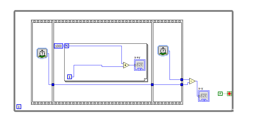
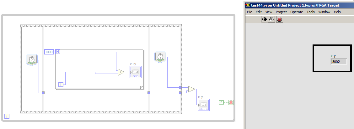
After complition process the vi was executed on fpga and read the number of cycles in the pc with the real time and the number of clock was 5002 clock as shown below
What is c?
is their any wrongdoing in my vi
mangood wrote:
So if a system (add many components, sub) and put this system inside the ""while loop"
Inverse of the period of the loop will be the frequency of the loop. Or frequency system is true!
-----------------------------------------------
I'm sorry for the stupid question, but my work on the architecture of the systems so these parameters is crucial and important for me.
I left my old job on tool company xilinx ISE because the design of the system to take a lot of time so I now moved into labview fpga, its amazing especially in the optimization process, but the clock Concept here is very weak and totally confused.
It's a different clock concept that most use of FPGA designers, it's true (I am trying to learn about it at the moment I'm doing some work software - C, not LabVIEW - on a processor clocked inside an Altera FPGA). For a normal programmer it makes sense - it works just like it does on a desktop computer. On a desktop computer you do not need to know how fast the processor is, you just need to know how long it takes your code to run.
I don't know what is the distinction between the loop and frequency of system for you. There could be other components of the system that are running at a different frequency that you don't see, but are required by the LabVIEW environment (for the acquisition of data or communication with the host processor), but your code inside the loop runs at the level of the loop which can be measured with the number of cycles.
Tags: NI Software
Similar Questions
-
Delay FPGA using a derived clock
Hello
Probably a simple answer to this. I have the PXI-7813R that has a clock of 40 MHz I database I need to create a delay time of 488nSecs in my code. Unfortunately with 40 MHz, I choose 475nSecs or 500nSecs. If I use a clock derived from 80 MHz I get a 487.5 delay which is very close to what I need. However, if I change my level above 80 MHz clock I get various offences of timing during compilation. Is there a way to keep the clock of 40 MHz top-level, but use the clock of 80 MHz for a time delay?
Thank you
Andy
Hi Andrew_Quick
Do you use this clock derived on a SCTL? I did some research on your question and find Knowledge Base article next talks a little about the way in which the clocks derivatives works with the SCTLs and in section shifts, there is a note that some codes can compile not at higher rates at 40 Mhz due to the time constraints of the FPGA , so I think that you should check that you don't have warnings or suggestions for when creating your clock derived to your target.
Even if you select the clock 40 MHz as the top level, if you select the clock of 80 MHz for the timed loop, the compiler will have to adapt all functions in the FPGA, and according to the error that you get that may be causing the violation of timing.
Hope you find it useful!
-
problem of delay FPGA can understand
Hello I have labview pci virtex 2 card in the computer and try to implement DMA from the host to the fpga (I use a clock of 200 mhz, which is the first of 40 MHZ with pll multiplier)
but every time I have an error of period not comply with the requirements of compilation happens that I can't understand how to fix it
I tried changed settings tick and insert the delay loop, but does not change the error
I have attached the results of error timming
can I get help on hw to solve?
Ghattas.Akkad wrote:
If a fast clock should not be better then a slower?
What do you mean by "better"? Faster, the clock, less you can do in a clock cycle. Your code uses a single-cycle timed loop, which means that the entire interior of the loop must run within a single clock cycle, and there is also a lot of logic in it to run at 200 Mhz. A fast clock is not better than a slowdown, if it is not possible for the code to run at the faster clock speed. Why did you choose 200 Mhz?
It is also unnecessary for the structure of the sequence, even if this is not bad no matter what.
-
create the example simple encrypt/decrypt string - but without success
Being a newbie crypt I'm trying to build an example of simple string encryption/decryption, but somehow the decrypted result differs too much :-)
Can someone tell me the error in my reasoning? Thank you!
import java.security.InvalidKeyException;
import java.security.NoSuchAlgorithmException;
import java.security.NoSuchProviderException;
Import javax.crypto.BadPaddingException;
Import javax.crypto.Cipher;
Import javax.crypto.IllegalBlockSizeException;
Import javax.crypto.NoSuchPaddingException;
Import javax.crypto.spec.SecretKeySpec;
public class dum_8_decrypt64 {}
Public Shared Sub main (String [] args) throws NoSuchAlgorithmException, NoSuchProviderException, NoSuchPaddingException, InvalidKeyException, IllegalBlockSizeException, BadPaddingException {}
Dim input As String = "Hello, world!";
String key = "nv93h50sk1zh508v";
SecretKeySpec key;
Encryption cipher = null;
Encryption by dcipher = null;
The string result, dresult;
key = SecretKeySpec (passkey.getBytes (new), "AES");
encryption = Cipher.getInstance ("AES/ECB/PKCS5Padding", "Sunjce())");
Cipher.init (Cipher.ENCRYPT_MODE, Key);
result = new String (cipher.doFinal (input.getBytes ()));
System.out.println ("encrypted-> string" + result + "<-");
dcipher = Cipher.getInstance ("AES/ECB/PKCS5Padding", "Sunjce())");
dcipher.init (Cipher.DECRYPT_MODE, Key);
dresult = new String (cipher.doFinal (result.getBytes ()));
System.out.println ("decrypted-> string" dresult + "<-");
}
}
Output:
Encrypted-> string.
p ÿƒG¬µ? (.« <----------
The decrypted-> string Qbkuu $Ñ 5oaw'?) ; Yeutdp3wvk < -.Encrypted data is binary.
String is not a container for binary data.
-
TCP/IP read returns new data with a huge delay
Hello
I did a server using LabView application. The application translates simplified data of a device and translated them into more complex protocol with another party. The problem is that responses from my application take too long. I tried to analyze the response time in wireshark, and the NIC accepts data in time, but the function "Read the Protocol TCP/IP" labview returns with delay, sometimes several seconds.
The application uses asynchronous calls to perform the communication for each parallel of client modules.
I had a nonreentrant function reading tcp/ip common to all modules of communication cloned, while they were blocking execution for the other
 (facepalm).
 -
Multitrack editing live streams: pitch shift causes huge delay
All,
For a live stream, I use a multi-to change a number of effects. Everything works very well. However, as soon as I add (even if it's the only effect) a Pitch Shift effect in the basket of the effect, there is a delay of 3 seconds between entry and exit. Is there a way to "fix" this return to the small delay of a few tenths of milliseconds, as happens when you use other effects? 3 seconds streaming live pretty much done behind impossible. Thank you.
Help to the CC.
All real-time effects will present certain amount of latency, which is offset by the playback engine by a certain amount of flow of pre-treatment. But changes to these effects with latencies more will take more time before the changes are audible if modified during playback. You can take a listen to some free VSTs that can have an impact on the ground and can run more quickly to changes. VST 4 FREE-Pitch Plug-ins is a good starting point.
-
Huge delay during the image transfer
Hello
I use jenoptik radars XT 5 core with labview. I would like to take the image data and make an image processing. Unfortunately, I have only one option using its library in labview. Here it is:
I measured the execution time of the GetAcquiredImage function at the beginning of my code and I saw that time approximately 1 second. He is far behind for my task. May I ask how I can reduce the execution time?
-
is this normal for the printer to expire after a period of no activity?
Yes, the printer may go to sleep. Why?
-
A few minutes ago my PC was working fine. Then it suddenly fixed and restarted. Since then, it keeps freezing and crashing. When I try to open my browser, it does nothing, then after a minute, it crashes. Ditto for Solution Explorer and other programs. I had to use my phone to post this question.
I have currently no anti virus installed so I thought the possibility of a virus. I hope that someone here knows what is happening.
Hi Mollie,
Thanks for posting your query in Microsoft Community Forum.
There may be possibility of threats on the computer that you are running an anti-virus program. However, you can use Microsoft Security Essentials to protect against viruses, spyware and other malicious software. It provides free real-time protection for your computer.
Step 1: Now the computer crashes and restarts, allows first tent to boot your system into a State of services necessary to the operation and a minimal set of drivers enabled, called Safe Mode.
You can refer to the following steps:
- Remove all floppy disks, CDs and DVDs from your computer and restart your computer.
Click the Start button, click the arrow next to the shut down button, and then click restart.
- Do one of the following:
- If your computer has a single operating system installed, press and hold the F8 key as your computer restarts. You need to press F8 before the Windows logo appears. If the Windows logo appears, you need to try again by waiting until the Windows logon prompt appears, and then stop and restart your computer.
- If your computer has more than one operating system, use the arrow keys to select the operating system you want to start in safe mode, and then press F8.
- In the display Advanced Startup Options , use the arrow keys to select the option of safe mode you want and press ENTER. For more information about the options, see Advanced startup options (including safe mode).
- Log your computer with a user account with administrator rights.
When your computer is in safe mode, you'll see the words Safe Mode in the corners of your screen.
Step 2: Once the computer starts in safe mode, perform the clean boot to rule out a software conflict.
Put your system to the clean boot state helps determine if third-party applications or startup items are causing the problem. You must follow the steps in the article mentioned below to perform a clean boot.
How to perform a clean boot in Windows
Note: see "How to reset the computer to start normally after a boot minimum troubleshooting" to prepare the computer to start as usual after troubleshooting.
Step 3: I suggest you to run Microsoft Safety Scanner to remove all the threats on the computer.
The Microsoft Security Scanner is a downloadable security tool for free which allows analysis at the application and helps remove viruses, spyware and other malware. It works with your current antivirus software.
Note: The Microsoft Safety Scanner ends 10 days after being downloaded. To restart a scan with the latest definitions of anti-malware, download and run the Microsoft Safety Scanner again.
Note: Data files that are infected must be cleaned only by removing the file completely, which means there is a risk of data loss.
Hope this information is useful. If the problem still persists, please post back for further assistance, we will be happy to help you.
-
problem running example project USRP FPGA connected via Ethernet
Hello
I am trying to run the example project of USRP FPGA on a USRP-2940R connected to a PC windows using Ethernet. I have not made any changes to the FPGA VI or screw host and I'm tryign to run the host Rx in Streaming, VI. I get the error-63180 function Open Bitfile dynamic reference (called from the VI open device), with a possible reason for "the specified resource name is a reserved word or an invalid alias. Alias of RIO can only contain alphanumeric characters, '-' and '_ '. I specified an IP (192.168.10.2) for entry of address of device to function. I guess the address of the device is the problem. This who should I be specifying the address of device in this case. Any help would be greatly appreciated.
Jerry
jerrysydir wrote:
The restriction you mentioned is specific to the USRP platform? The website NOR talk using Labview FPGA with a RIO Ethernet expansion chassis. (http://www.ni.com/tutorial/11703/en/).
LabVIEW FPGA on Ethernet is only available through LabVIEW RT. Behind the scenes of the target is still connected to the well RT via PCIe controller and then the RT controller is connected to the host via Ethernet. There are also some USB LabVIEW FPGA targets (http://www.ni.com/white-paper/14821/en/).
For the RIO USRP, MXIe is currently the only bus taken in charge for LabVIEW FPGA.
-
Example of a simple RESTful POST service?
Hi all
I wish Oracle had provided an example simple RESTful POST service and does part of the Apex 4.2.x documentation rather than put the only example of a POST in the Apex listener (now Oracle Data Services) developer documentation. Also, why not complete the lovely examples in the "oracle.example.hr" with additional methods supported as POST instead of using a more complex example in the documentation for the listener - the sample picture gallery?
So my question is: someone at-it a fine example of text, data digital POST method that includes the creation of RESTful services and then the code needed to perform the JOB to the RESTful service - with an example application Apex or even the content of the URL which must be passed to the RESTful service to get the data in the table (for example, EMP or models of tables DEPT).
Thank you
PM
All,
Decided to meet myself in case someone else was looking to meet that time - found a very good example, exactly as I described above.
I was able to create the RESTful POSITION myself, but this thread has been very helpful in leading me to test the MESSAGE in an application and create the Web service reference.
I guess that it does not appear in the search because of the misspelling in the title of the question.
Thanks Anthony!
PM
-
How can I specify a delay generates a pulse meter?
Hi all
I have a question on the use of the meter to generate the pulse train. I did not how to program but I try the test panel in MAX and I see that it generates pulse train to certain rates and with a pulse duration. I think if it is possible to generate only a single pulse with given the duration of the impulse to sometimes after I start the job? I have a code to generate an analogue waveform, waveform of 35ms. I wonder if it is possible to synchronize the output of the analog waveform and counter such to 12.5ms after that the output waveform has started, I send this unique pulse from the meter port on. I have no idea how to do that, I think to use a delay but it is difficult to accurately control the time exactly 12.5ms.
Well, assuming DAQmx_Val_Low for the resting State, fires the meter will wait the initial delay and then generate a pulse at the time you request. Little time is not actually used in this example simple impulse.
From what you described, you must add a trigger to start your task of meter output (DAQmxCfgDigEdgeStartTrig) to you can set the meter to trigger off the beginning of analog output trigger. Set the initial delay on the counter for 12.5 ms. Start the task of counter in front of the task of the analog output. You should get your pulse 12.5 ms after you have started the task of the AO.
Best regards
-
PCIe-7842R (series R FPGA) digital output does not work properly
Greetings,
I'm having some problem show TTL the correct voltage with my PCIe-7842R FPGA board.
The block diagram of my code FPGA LV Moose appears in "analog - digital .png '. The idea was to convert an analog input (decimal value) to a binary code and 16-bit output by 16 DIO ports. I use the connection block SCB-68 has as the terminal and trendy on the FPGA 1 connector RDIO with SHC68-68-RDIO shielded cable.
The compiled code ok. But during the test, I noticed that some ports has no output TTL levels correctly. For example, for input 1000 decimal, I would expect binary code 0000001111101000. However, some ports (DIO #6, #7, #9, etc.), which are supposed to ~3.3V (1 digital) high TTL output, output actually 0.8V. I have attached the result measured in 'exit digital test.png '.
To ensure that the question was not because of the code of the LV, I did some more tests on DIO #6 with a simple example (simple digital output.png). The output was ~ 1V this time at the digital 1.
It's really confusing because of the digital Edition is supposed to be simple. I used the same FPGA card for controlling roller shutters with TTL signals before and it worked fine.
Does anyone have similar problems? Any suggestions are greatly appreciated.
iron_curtain wrote:
DIOs are connected to a controller digital galvo Cambridge Tech. But I measured the voltage at the terminals of the connector block.
If you unplug the controller galvo DIOs, do they look good (have the right voltages). Do you know how many of these entries to the need for controller? I think you hit the limit the total current available for EID within the Council.
-
delay in the structure of the case
Hello
I use a structure of cases within a while loop.
I want to put a delay of about one second whenever the case goes wrong (it must remain false until 1 second) then comes to the usual routine. I tried to use the function wait (ms), but then it effects the while loop. is it possible to put a delay without the normal time of the while loop operation?
I enclose an example simple vi to clear my point.
Thank you
Here is an example of using the last timer.
-
Attached in Lightroom 2015.3 produces enormous delays in the transfer of image
I turned to a concert last night and because client that I needed to perform impressions during the event, chose to use Lightroom attach to my MacBook Pro to get the images in Lightroom, because they were shot. Repeatedly during the evening, the camera seemed to lock up and the lamp of data transfer was on for minutes at a time. I see delays of a few minutes before the captured images would get to Lightroom, and then after waiting a while, things would be back to normal. Then in a short time, everything would be bogged down again. By stopping the attachment, the issue disappeared completely and I could only shoot the required event. A break, I tried to tie up again and the same problem occurs very quickly. In my tests before shoot, home seemed to work, but I did not test the volume that require the event (3 images every minute and a half).
In the past, attach lose connection randomly but the connection remained all the time, however huge delays in fact transfer the strap works more an argument than a boon. Others have experienced this with Lightroom 2015.3? The environment was very simple. 1Dx cannon with a strap tools cable for MacBook Pro running El Capitan and Lightroom 2015.3
Any advice will be appreciated. Earlier in the week, I had made a similar shooting using Canon native tethering tool and never had these problems and was running at a much higher pace, using the same physical hardware.
Ross
Hey Ross,
Please read the following article and let me know if it helps: captive troubleshooting capture in Lightroom
Kind regards
Tanuj
Maybe you are looking for
-
I need to download a digital certificate, version 35.0
To get a digital certification the emisor company asked for a version of Firefox 35.0.
-
I can't find the start page in Firefox with the Set Up synchronization link
I try to get the synchronization on my android device code find all my favorites on my main computer to the tablet-PC. The directions on the Mozilla support site say "Type set up button on the start page for Firefox Firefox Sync." Well I can not for
-
Satellite L755 - 13 X based virtualization?
Hello I want to know if Satellite L755-13 X supports virtualization? Are there measures to enable it in the bios or something? Thank you
-
Satellite A300D-15B touchpad plays when the external power cord is connected
I got an A300D-15B for about 2 months and while using it I noticed that the touchpad is hyper sensitive or do not respond.I tried all settings (and it works fine when the advanced settings window is open!), but return to a document or a Firefox windo
-
Presario cq-57: cq-57 bios lock
My future ex-girlfriend just put a bios password on my laptop. After that three attempts to connect, I received a message 'SYSTEM' OFF with code according to [62313085]. Please help me