simple xy graph
Can you set an example on how to make a simple external entrance graphic on the y-axis, the current time on the x-axis? Could not find an example.
See you soon
This is u...
Tags: NI Software
Similar Questions
-
I have
10 channels.
How can I place more channels on my chart xy
?
And here's how you would be graphic 10 columns using a simple waveform graph. much simpler.
(Note that you can omit the operation of transposition and set the chart to transpose into their own country).

-
"Graph - Simple" change issues to include several axes
I'm changing the workspace "Graph - Simple" object to allow several axes. However, I was do unexpected behavior and I can't find a way to restore the configuration when the next load.
- Is there a way I can use the "Custom Data" variant in the Item.Data cluster to store the configuration?
- If not, is there another way I can do this work within VeriStand without having to re - develop a full graphical object (based on the free label template) just to add this feature?
I am currently using VeriStand 2014, but I can be updated until 2015, if there is a new feature that would help.
Thank you!
You're very close to having the right answer, but what you call won't work, unfortunately. Overall, it would be nice to put data in the custom as attributes of variant data field, as long as you crush all VeriStand attributes can be expected otherwise. Even if you do this, however, there is no way to save this copy of the cluster of the top-level VI item data. I can't in any way you can get this to work.
However, you do have to start from scratch. It is an available add-on here called Multi-Y chart with channels calculated. It has multiple scales are natively, but this is a graph open source with a superset of the features in the chart - simple. Here you could probably change to have two or more axes and find a good way of saving data so that it persists on the next load.
I did not write this control and never used personally, but it might be a more open alternative to watch before thinking to start over from scratch.
-
Several waveforms in a simple graph
Hello
I need to compare several waveforms (max 10) in a simple graph shape wave. Few of the waveforms are taken directly from Tektronix 11801 B sampling oscilloscope and bit the previously recorded data come from or may sometimes come from the oscilloscope itself... I did it for the two waveforms and it works perfectly... I just wanted to know if I should get all the waveforms of the instrumetn directly for comparison, do I have to repeat the same procedure for 10 times or y at - it another way to do it?... I'm fairly new to labview... could someone help me please
Joined the vi that I did for 2 waveforms
Concerning
Julien
Hi Alain,
an example, as requested:
-
Draw two graphs, a simple graph
Hello. This is my first time using the command and the simulation. I want to draw two graphs in one graph. It seems that I have to use together and to build tables functions but I don't know how to draw them. The points x and y (2) are only defined by a single set of points included in the defined table. The points x and y (1) are the results of another formula, but the two parcels would fit in the same location in a single chart. I hope that my question is understandable. I attach a portion of the model I want to be plotted.
Thank you
Hello
You can try something like that. Check the attached VI.
Kind regards
Amine31
(Give congratulations to good answers and Mark as a Solution If your problem is resolved
 )
) -
I want to do a vi that can "" "simulate" ' "ohm's law...
I mean
I = V/RSomething like that might work.
-
Create a simple target line in a graph
The only way I can create currently a target line is to create a dummy column and set my target value. Then put this dummy column in my measurements of rows in my table. Three issues that I see with this are:
(1) line is not the entire table from left to right.
(2) target line is coded in my dimension of color values
(3) an another annoying thing, the target of title is repeated for each value of the coast
There must be a way to create a static row that is not based on a dimension and the ability to keep my own legend.
I've linked a sample below:
http://i.imgur.com/BC844pU.PNG
Thanks in advance
Curious to know if anyone knows how to create a solid target line?
Thank you
-
First HP: Lack of Sections of first graph with steep slopes on HP
I saw somewhere an old post on the Internet where a user was having difficulty to see the graph of y = x ^ 4 (x-2)(x-6) using a "Decimal point" display window and the "Evolutionary" method in the application of the function. The chart has not demonstrated the branch of the chart with the x origin of (6, 0). The response at the time was to use a different window or switch to advanced graphics application. I don't like either of these options, because much cheaper calculators have not this problem.
With a little experimenting, I found that the calculator will be graphic curves where the absolute value of the slope (derivative) is less than about 375 * (Ymaximum - Yminimum) / (Xmaximim - Xminimum) where the minimum and maximum levels refer to the values specified in the configuration of the land. When the curve is steeper than this amount, the curve has holes and gaps until this value exceeds of approximately 1500 *(Ymaximum-Yminimum) / (Xmaximim - Xminimum). At this higher value, the curve is usually not in graphic form at all. These expressions are based on the study of graphs of the polynomial given above, y = 1 / x and y = e ^ x for different values of configuration of land.
I realize with the option of touch screen on the first HP for the graphics window resizing, calculator, developers should be a little more sophisticated in how to get the calculator determine the graph. The current 'Adaptive' method is too risky for me to use unless I know a little on the chart. And the graphic progress is too slow. HP working on another option or is there maybe a setting on the computer I do not use its full potential?
I've only used the calculator for a few days, but others who have used the calculator for many more are also puzzled. Thanks for any info. You can send our way.
It is currently being considered. I can't say when / if there will be changes, however on the political basis of HP on 'future-looking '.
However, graphical representation is one of those things that is "deceptively simple" because it seems to be pretty easy but is actually infinitely difficult. It has in fact been mathematically proven that you * don't * create an algorithm to be quite accurate for the same simple algebra. All graphics engines turn example is a very simple method that collapses quickly for something else then the case of some, it's well, a series of different behaviors for different types of problems in an attempt to account for different types of situations.
The average general graphic has been done in the past was "moving pixel, evaluate and connect the dots." This works for simple things, but falls apart pretty quickly. Most of the calculators except the first on the market at the present time use some techniques of "smoothing" kind of hide the types of problems, this method can generate and generally work well for simple cases. While that hides things, the problem is he hiding things. :-) In more complicated cases, it actually makes things quite worse.
In this simple case, most of the systems actually get the "right" result because they always assume that a big jump in values one line drawn to connect them. Result directly in other cases where it draws a vertical line to an asymtote that shouldn't be there. That's why things like Tan (x) go very often vertical asymtotes where there shouldn't be any. To try to avoid this, you need the code to make a special analysis in the case of start trying to filter false positives. It seems that in this case, it is bad filter and eliminate the line here.
For another thing of pleasure, try the example simple "sin(e^x)" on all your systems. You will get some pretty crazy things and strange patterns here where there should not be any. The "speculative", the first will be closer, but only the grapher advanced with its graphics of interval it gets correct.
So in short, yes - you put this to our attention. In long, graphic representation is in fact much more complicated then one might expect. :-)
-
Binds the data object graph, causing memory
Hello
I want to create a WPF application that uses Measurement Studio to display the data points on the graph.
We have already implemented a HAL, the data in the reports of the UI (after a few manipulations), using the DAQmx.
I saw in your examples you display only the last second points, but my users can choose to see the data in an hour, and if I continue in the data memory of the points for the last hour I get out of memory (the data object become very big).
How can I display in the chart of the data of the last X minutes / hours without keeping all the data in memory?
Sorry, it was my fault (the years were defective in my local test as well, just, I had not noticed). Fortunately, what makes the solution even simpler: the
CustomXAxisimplementation can change justobject ISourceDataProvider.TryGetSourceDataStart() { return default(DateTime); }.Also, for future reference: to the changes of the properties in WPF, you must be a dependency property or
INotifyPropertyChanged, but not both (i.e. didn't need youOnStartTimePropertyChangedinCustomXAxis). -
Build the table to 2 dimensions to plot a graph from UIMessages
Hello guys,.
I need some advice, the problem I have is that I want to pass an array [0 5] numbers to my throwugh of custom UI UIMessage to plot a graph with these data in the same grapgh (see the behavior of the 6 signals on the same graph), but so far I could only pass a value and see only a signal in the graph.
Is there a way to pass the french table UIMessage using the activeXDataParam? Or may be otherwise?
Thanks for your comments.
Eder
I threw together a simple example in TS 2014 and 2014 LV. I think it does what you want. Simply run the main vi in the project and select the random sequence file Array.
In addition, attached is a photo of my UserMessage vi.
Hope this helps,
-
graph waveform of several sensors
Hi, I receive data from 50 sensors with a microcontroller. Data from the sensors are stored in LabVIEW in an array of cluster, each cluster containing a unique sensor info. I need to display a graph of trends of the curve of value 3 of all sensors, so that each sensor should be represented by a color. The data are updated every minute. Can someone help me please?
First of all, I'm sure you want a graphic, not a graphic. A graph keeps a history. A chart shows just the last thing you wrote for her.
Secondly, to make the building of the waveforms within the loop FOR. Makes things MUCH simpler.

-
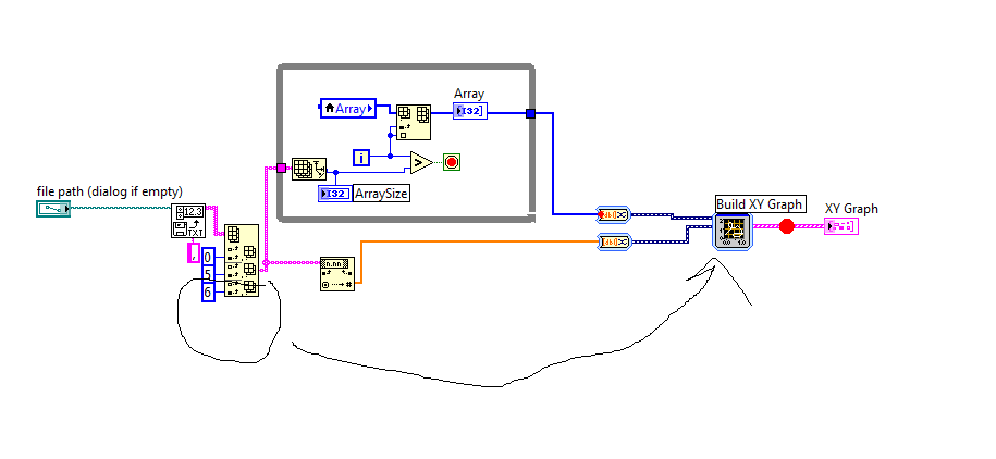
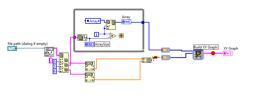
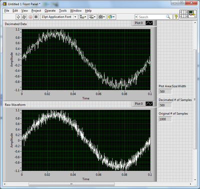
How the graph data are resampled pixels?
A test, I created two identical graphs with land areas 500 pixels wide and a noisy sinusoidal signal of 1000 samples. A chart displays the waveform right, while the other got the results of the use of the function Arrray to decimate to halve the number of samples. They are not the same.
Up to a waveform graph does exactly when it displays a data value larger than its width in pixels?
As you have noticed, the graph is a little more intelligent that you expected. When the number of points exceeds the number of pixels, a form any resampling must take place. A simple decimation as you tried would eventually pass some interesting points. Instead, the outliers receive priority when selecting which points to display. Strong in this way, peaks and dips appear even on a large scale. Reproduce this behavior yourself can be tricky. And once you reduce the data set, the points are gone and zoom is not as effective.
Usually, I try to let the chart to do as much as possible. A simple and effective way to reduce the size of the data you have to ship on the network is to use the SGL precision instead of double precision.
-
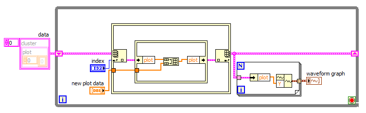
XY graph multi plot points and color control live
Hi all
I'm doing something that should be simple, but difficult so far. I had a good look through previous topics and found similar things, but not really what I want.
In my experience, I'm scanning intensity vs. wavelength.
Ideally, I want to be able to:
(1) scan and see live plotted points.
(2) then I want the plot to stay on the graph when I run the following analysis, etc.
(3) I have an arbitrary number of scans. for example to start a scan, I press a button, an arbitrary number of times.
(4) I want to make sure the current analysis is drawn live in (red), and all the previous analyses are drawn in a different color (blue).
(5) sometimes I want can erase the graph of all scans and start over, without having to stop the VI.
Items 1-3 can be supported easily by placing the XY graph building and the XY graphic object inside the loop that runs the scan and uncheck 'clear data on each call' in the properties of graphic generation. See the first VI attached.
However, at the beginning of an analysis, she joined the last part of the previous analysis up to the first point of the next scan.
The difficult parts are 4 and 5.
For article 4, you need to build an array of plots, which is easy if you know the number of plots, but here the number is arbitrary. So, how do I do that? I had a go trying to use Insert table in different ways, but I haven't worked on it. Then if all goes well using the graphics property XY nodes I can adjust the colors of the plots.
For part 5 is not just enough to use the invoke = node reset by default, and have a button that executes the node. This clears the graphic but then when you run the following analysis all parcels previous pop up once again, indicating that the table that stores the plots is not actually deleted. The second accessory shows how I delete the chart.
My biggest problem is point 4 and combining point 4 and 5 together.
Help, please.
I fixed the problem of the route doubly table and added in the desired color, attached plot.
The code now done everything I wanted to in my first post.
No doubt the code could be improved more, but that's for everyone out there who has this problem.
Thanks to tst for give me useful advice.
-
Graph waveform repeats with each iteration of the loop
Hi guys,.
I got some great responses from you many already, so I hope you can help me once more!
I try now to simply take a voltage that is measured by a sensor, I tied to AI1, and I built a graph of very simple waveform using a DAQ assistant. I have the setup terminal to CSR, the acquisition value continuous sample mode and read samples and rate game to a control on the Panel before which I can control myself. All this is a while loop that is needed to collect data over time.
However, the problem I have is that for each loop of the loop, it seems, to reset the graph, so my x-axis never increases over time, ideally I want it to do is to show results through from 0 to 100 on the x-axis to say, and then, when it comes to 101, he will start again on the extreme left of the graphic to the right to a crossing another 100 points given) (there's a term for this, but I forgot, sorry!). To be honest, this kind of logic like everything in the loop will be restarted, but after trying to chart the loop it does not work, so I'm fresh out of ideas.
I think I might have to do is to manually build segments of data acquisition (DAQ mx) and have only certain parts of them in the loop, although I can't be sure. I tried various examples and online on the database of NOR (including tension-int acq & graphic clk which works well in the examples, but not at my request) but no luck for now

If anyone can think of what could be the problem, then please let me know. FYI the sensor is optical fiber if it makes a difference. I have attached the file VI that I did does not really...
See you soon!
Ritchie
Since you use a chart there is no way to fix it. If you choose to go to a XY chart you could solve this problem. See the example below.
-
How to make a graph in the hour
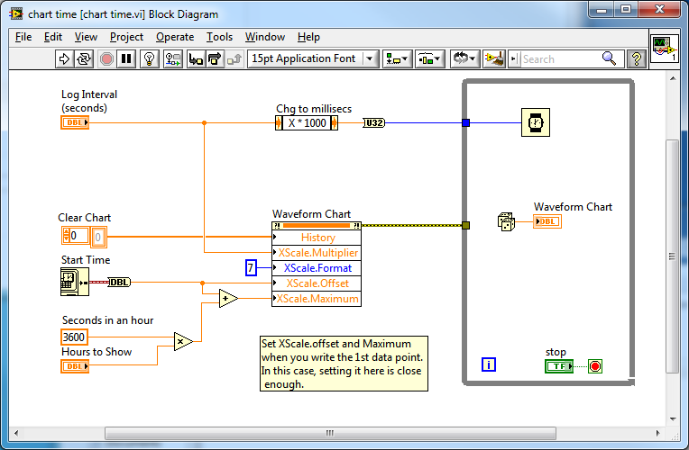
I have an application that runs without interruption and sends the data in a txt file. I have labview then read this file and display the content on a chart. I want x-axis it in the chart in the correct local time, so that users can see how the data changes throughout the day. Ideally, it would show the data over a period of 24 hours with the max being present and the minutes being the time 24 hours ago. I guess it has something to do with the time stamp and is probably simple, but I can't understand it. Any ideas? Thank you
Hi James,
If you know the start time and the sampling interval so you can have the picture of the value of the axis of time for you.
The value of the graph axis X hour Relative. Don't forget to set the length of the graphic story to be long enough to display all the samples you want to display.
See the attached example. Here's the diagram:
Steve

Maybe you are looking for
-
My 5s iphone serial number is changed. Why?
My iphone could be used for 5 months after the purchase. Serial number was F2 * NJL. After 5 months, I don't know why that my phone could not be used. And the itunes logo appears. I tried to connect with itunes and to restore the software as many tim
-
How can I get a transparent countdown in my video (10.1 iMovie)?
-
Police Wingdings 3 is no longer an Option in LabVIEW 2015
My company just put update 2015 of Labview. In a number of legacy VI, Wingdings 3 police was used to display the up and down arrows. Use an image to display the arrows is not an option and Alt Codes display in the form of '?'. If I highlight text,
-
BlackBerry smartphones can not connect 8230 to Desktop Manager
Last week I can't get my 8230 curve to connect with my Desktop Manager on my XP or Vista machine. It was working fine all this while but it suddenly did not connect this last week. Would it be a software update or something from Microsoft? I use v4.2
-
My blackberry app world phones smart blackBerry went from what I've been...
My blackberry app world went all in GBP to all be in USD. How can I change back so that my location and currency are right?