Suspension of a write operation to DAQmx
Hi all
I use a DAQmx with the cards NI9402 and 9264 to control current amplifiers for an MRI System. I intend to do using a waveform table raised on channel 3 of the NI9402 (high-speed digital input).
The difficult part is I need to pause the write operation once a given number of points was written until the digital signal is reset, how the rest of the buffer can be written.
I'm not satisfied with my current solution because it is ugly and is rather slow. There is a minimum of 70 ms between the operations of two scripts, which is not acceptable. I need a minimum waiting period of 10 ms.
I'm not familiar with Labview, but I think there may be a way to use the clock for this signal? Unless someone sees a better way to proceed?
All the best,
Lionel
Hey Lionel,.
I thought of a way to do this completely in hardware. You will need two counters embedded chassis cDAQ, 4 channels of your outdoor wiring 9402, and some (including a BNC T so that it works well). I briefly checked that this method works, but I have probably not thought through every possible corner cases. My code works as follows:
- Set up a finished counter of output to generate samples N, where N is the number of samples to produce after the initial rising edge of the trigger signal. Out of this train of pulses on channel 9402 0 (PFI 0). This task is to use the amount of 9402 channel 3 flank (PFI 3) as a starting signal.
- Set up a different output over counter to generate samples of M, where M is the number of samples to produce after the trigger signal goes low return (total of samples or less N). Out of this on the 9402 1 channel pulse train (PFI 1). This task should use the edge falling from 9402 channel 3 (PFI 3) as a starting signal.
- Using a BNC T, combine the PFI 0 and outputs 1 IFP then their thread 9402 channel 2 (PFI 2).
- For your analog output task, use a value over production task generate N + M samples with the clock set to PFI2 sample source.
I tested it with an SMU-6363, assign a sinusoid point 4000 to 1 ms/s output. With N the 2567 value and the value of 1433 M, I got the following result. I can change the values of N and M, and it still works well.
I post my code, but honestly, I just did some quick changes to the over voltage output – over output and Counter – expedition of the examples (under DAQmx in the Finder of the example), so I don't know how much value he would add. Let me know if you have any questions well, or if this is not possible for some reason any.
Tags: NI Hardware
Similar Questions
-
I can't write operating records
My hay program mast view some data from a controller. This with an Ethernet connection. I read everything and I can write coils bet I can't write operating records. I hope someone can help? Heir my VI: Rutte
With split or join in the digital numbers / range of data manipulation, you can take two U8 and join them in a single U16 (and vice-versa using split). And you can take two U16 and join them in an only U32.
Take a look at the attached Subvi, I did. It is a wrapper for the Modbus VI functions so that I could use enumerations to read or write specific registers by name and manage the manipulation of data as a result. It may call for a couple of typedef, that I created for my particular application, but that should not prevent you to see the structure and how I did the manipulation of data using the split and join.
-
Could not read a DVD after the write operation
Using windows XP sp3.
I burned a dvd with nero data disc 9 esentials and then couldn't read or any other disk.
Tried the disc in my computer vista laptop and it read fine.
DMA is enabled.
After a lot of noise, I restarted my computer xp and it will now play dvd's and discs again.
I noticed that there are several entries in the device for ide primary and secondary Manager.
Here is a link to the screenshot:
http://AG1.dnsalias.com/photo/devicemanager.bmp
Could be the problem?
Now, I think that the problem may be due to the Nero 9 Essentials program if you close the program immediately after the write operation instead of clicking next and then closing. Thanks for your help.
-
Oracle coherence first read/write operation take longer
I'm testing with consistency oracle Java and C++ version and both versions for writing in a local or distributed or near cache first read/write operation take more time compared to the next consecutive read/write operation. What is because of boost operations inside real HashMap serialization or memory mapped implementation. What are the techniques that we can use to improve performance with this first read/write operation?
I'm doing a read operation / written after extraction of the NamedCache Instance. Please let me know if there is any what other stimulant coherence cache of available techniques.In that case, why bother with consistency? You're not really winning anything, are you?
What I'm trying to explain, is that you're probably not going to get this level of performance 'microsecond' on a consistent cluster configuration, running on multiple computers, passes through proxies for clients c ++. Consistency is designed to be a scalable, tolerant cache/processing system and distributed. It is not really designed for real-time, guaranteed processing, micro-nano-second second level. There are much better batteries product out there for this type of treatment if that's your ultimate goal, in my humble OPINION.
As you say, simply write a small local map (or an array, list, Set, etc.) in a local JVM is always going to be very fast - literally as fast as the processor running on the computer. But this isn't really the development of a product like the consistency. It does not seek to "get the gun" that you can get on a single machine, perform simple processing; Consistency is designed for scalability rather than outright performance. Of course, the use of the local caches (including coherence near caching or replicated caching), can you put some of the performance you ' lost ' in a distributed system, but everything is relative.
If you wander on some of CUG presentations and attend a few meetings CLOSED user group, one of the first things the support guys will tell you is "spots on a correct cluster' and not 'on a localized development computer. Why? Because the difference in performance and scalability will be huge. I'm not really looking to dissuade you from consistency, but I don't think that it will meet you needs when fully configured in a cluster of "1 Micro seconds for 100000 data collection" on an ongoing basis.
Just my two cents.
See you soon,.
Steve
NB. I do not work for Oracle, so maybe they have a different opinion. :)
-
NFC tags low level read/write operations
Hello
I know it's little bit offtopic question - but since you are experts in the field I will try you may ask a simple question:
1 / I want to know what protocol is used to read/write for the NFC operations, tags are used. According to my understanding after that the label is placed on the NFC (NFC, USB drive phone) reader, it is powered and set to the ready state. The application protocol for read-write operation is used. As I think that the format and content of the commands used to read/write is not specified in the ISO 14443 and it is based on a material/manufacturer and will be different for FeliCa, Mifare, Innovision, etc tags, so there is no way how to handle read/write NFC tags with unique implementation operations. This hypothesis is correct?
2 / are there tags, that supports the 4 7816 APDU commands for read/write operations?
Thanks for the reply
Kind regards
STeNHello
To read the NFC forum specifications. It will be better explained than by me.
several protocols are used according to the contactless front-end configuration and capabilities. It includes ISO14443-A, ISO14443-B and Felica. Sometimes the other protocols are also available, for example Innovatron (not Innovision lol)
Mifare is not a Protocol, it is a line of NXP products. These products use the lower layers of the ISO14443-A protocol specification.
There are 4 types of tags
(1) using the lower layers of the ISO14443-A
(2) using the lower layers of the ISO14443-B
(3) something related to felica?
don't know exactly on these 3, you should read the specs. Everything is clearly understandable, not like ETSI.(4) something using commands ISO7816-4 on top A ISO14443 or B or others. You must SELECT, BINARY, BINARY update READ. You can implement using javacard, I did it and it works. You need two binary files, which can be hard-coded.
Concerning
Sébastien -
DAQmx Synchonrized read and write operations on the same device
Hello
I use a PCIe-6535 to test a chip that we made in our research group. In order to quickly analyze the data, I have to be able to synchronize the reading and writing. We have an inspired interface to (toggle pin A, axis of the B scale, read C axis, toggle pin...).
We have figured out how to create a reading task and a writing task, but we have no idea of how to make the two simultaneously in order to implement this interface.
Have spent a few hours searching online, I have not found any that makes a lot of sense. It seems it should be really simple and common to...
Does anyone have an example or a tutorial that they can point us?
Thank you
DaveI spoke to an engineer of applications very nice who told me this, which is exactly what I need:
http://zone.NI.com/DevZone/CDA/EPD/p/ID/6200
There's even an example for my card
Thank you
-
The computer starts without the OS disc in the drive but then flashes this message and restarts constantly.
Hi Sys_builder,
Thanks for posting. Your operating system has already started successfully? If she has, I would say running a repair installation. If he ever started successfully, I guess you have bad media or bad material somewhere. I would check with the manufacturer of the hard drive to see if they have diagnostic utilities.
I hope this helps! Let us know if you have any questions. Shawn - Support Engineer - MCP, MCDST
Microsoft Answers Support Engineer
Visit our Microsoft answers feedback Forum and let us know what you think -
[ERROR] ISO [DAAPI] =-1: [I2C] failed to start the write operation: errno = 11
As this bug is pretty boring, I expect the GA 8 final Java ME will be corrected this. Are there plans when it will be available to the public?
Hi Markus,.
This bug has been fixed in drops later.
/ Sergey
-
Capture camera IMAQ via DAQmx trigger operation
Hi all
I thought I could re - this poster in this forum to see if I get more ideas!
I work with a PCIe-1427 card connected by link to a camera (SUI Goodrich) and also using a card PCI-6731 to which I attached a connection block M SCC-68 series.
I managed to write code to control the .avi capture the camera and write separate code to control the lighting of optical switch connected to the SCC-68.
The two lines of the optical switch Relay different info and I will in turn present this information to the camera for analysis. Ideally, I'd like to trigger the acquisition of the capture of the camera with the optical switching so that each image contains information of a single channel only, but I still fell in the integration of the operation of DAQmx meter with IMAQ camera code.

Is this possible? I see 1 previous post by using a RTSI cable can I connect the two devices together (or alternatively use the DAQmx to produce a trigger on the digital). Can someone offer information or an example on how to route signals via the RTSI to IMAQ DAQmx? Also do I tuned regarding the generation of pulses to the switch that allows signals to pass through RTSI?
I find it by running my camera and counter code in vi even both will work (not in sync)-if I connect the RTSI and select the camera settings to accept the RTSI triggers, if it was a simple solution?
I would greatly appreciate any ideas you may have. my time runs out very quickly and is really distressing.

Sincere greetings and thanks,
Miika
Miika salvation,
If I understand what you try to do in VI you attached, you want the output of the counter of the task DAQ to serve the trig by buffer task it IMAQ via RTSI.
To do this, use the property node of channel DAQmx to configure the output terminal of the impulse to be RTSI 0:
Select property > counter output > Pulse > output terminal
B. change the node property to write.
C. create a constant and select/Dev1/RTSI0
On your IMAQ configure Trigger VI, RTSI value as type, set to 0 the number of line, set the action to trigger each buffer and set the polarity to rising edge.
Oh yes, make sure to connect the RTSI cable for two cards. I forgot that before and felt really stupid later.
-Jeff
-
How to determine the number of highlight ' to write ' for DAQmx generate analog output?
On the configuration of the stage for DAQmx generate analog output, there is a field "value to write. I can't find any explanation for what it is, how it determines the value to enter, nor what he writes. I am trying to go through the tutorials and it cling.
Someone would give an explanation?
Hello
To write value specifies the value to write in the channels, lines or ports selected in string parameters. In other words, this value will be the value of your DC output (for example if you enter 5, your output will be 5V). To get information on different fields in SignalExpress, access help"context-sensitive help. A pane will appear in your work environment that displays the coordinates of the field when you place your pointer over them.
For new users of SignalExpress:
Generation of DC signals with NI DAQmx devices: step in the DAQmx build, select 1 sample (on request) in the generation Mode dropdown. You can select a programmatic input to generate, or you can remove the check mark from the check box use programmatic input and specify a value for generating in the field of value to write . NOR-DAQmx help also provides additional information about the data generation.
Best regards
M Ali
Technical sales engineer
National Instruments
-
Is there loss of data when I have other operations at an event?
Hello. I am a new user to NOR-DAQ.
Now I develop a sampling program HAVE continuous for the NI USB-6229 case.
The environment settings are 8 channels under 2 kHz sampling frequency. In the program
I need to save the data in a csv file each time than in quite awhile, let's 500ms, through the 'event '.
mechanism. I tested that it takes about 32 ~ 48ms to write the data of 500 ms.
This 'event' appears as a software interrupt for me so I was wondering if the DAQ hardware
continues to record new data while I perform the write operation in the case?
Or put in another way, when I set up the task of sampling with the function
"DAQmxCfgSampClkTiming", the "sampsPerChanToAcquire" parameter is described in
be used as a factor to determine the size of buffer. Is this the intended "AI FIFO" buffer buffer
by the "M series user manual? This means that if I put it to an appropriate value data
will always go in this buffer first and then read by the computer, so if the transfer is fast
enough, there is no data loss?
Thank you in advance.
Data are recorded by the data acquisition apparatus and stored in the FIFO buffer. The reading VI DAQmx then takes the amount of data specified on the FIFO and brings the data in your program level. So as long as your buffer is large enough, you won't lose any data.
Here are some other suggestions.
Focus on the architecture of producer/consumer . It is a way to put writing files in another thread to process and record data at the same time.
Lean on the function TDMS flow in the DAQmx palette. It is a way to bypass the program level and get a log file of the data. The data format will be PDM and not a CSV file. But there is a plugin to read the TDMS files in Excel.
-
Shared data varying variable published network write error
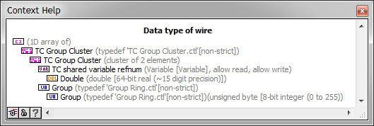
In my project in real time, on the VI host running on my Windows PC, I try to write in a number of published network shared variables. All these write operations are successful (which means that I can read them on the RT target, then a cRIO-9012), except for these shared variables network-published with data type defined as Variant. I'm not sure what is causing the problem.
I take the table of clusters shown here...
.. .and going through one "in Variant' VI and then subsequently in writing to the shared variable (data type: Variant). Diagnosis of the failure of the VI in real-time to read the data, I found that variable writing shared on the host VI produced the following error:
Error - 2147467259 appeared to Variable shared in the PC host TTS CTRL.vi
Possible reasons:
LabVIEW: Unspecified error (Hex 0x80004005).
=========================
System OR Configuration: Various operating default (Hex 0x80004005).This error or warning occurred when writing the following shared Variable:
Shared \\My Computer\Network Variables\TC trust Array Group - network
Shared \\128.144.90.143\Network Variables\TC trust Array Group - network.. where 128.144.90.143 is the IP address of the PC.
Any thoughts?
Sean
I saw this post, and when I found myself with no other option, I have redefined the variables in question to the string data type and replaced all the "to variant" and "given Variant of ' functions with functions 'Flatten channel' and"The string Unflatten"respectively. Initially, it did not work - functions "Chain Unflatten" would produce error 74, until I realized that the "data includes array or string of size? (T)"input on each 'string Unflatten" function must be set to FALSE. Wiring a constant false for each instance of "Unflatten to the string" seems to have corrected the problem.
I have still no idea why wouldn t Variant. Shared variables Editor allows to define a variant data type, so I guess it's supposed to?
Sean
-
DAQmx newspaper read and data at different speeds
Hey guys!
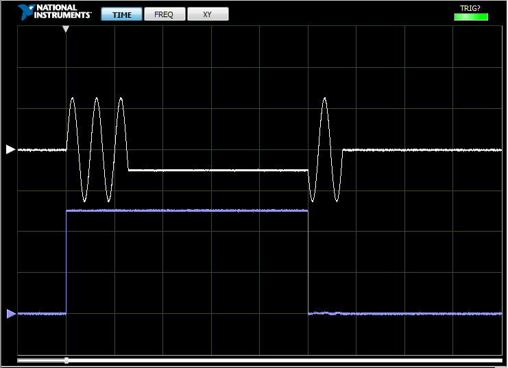
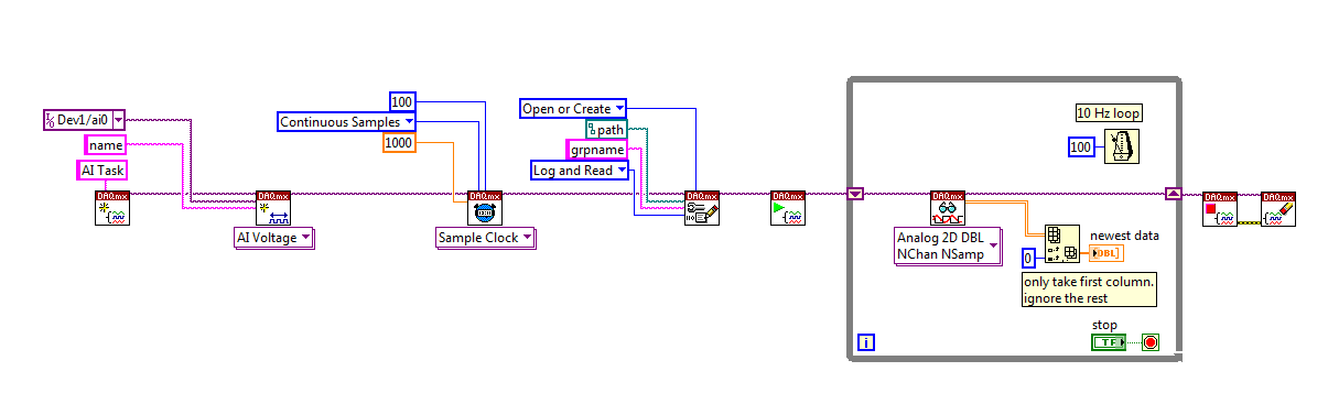
I use DAQmx to make playback of analog input. I would like the data be datalogged by TDMS at 1000 Hz. However, I want to only read data at 10 Hz. Is there a preferred method to do? The photo below shows what I have so far. (Note that this image is a simplification of the routine I use DAQmx)
As you can see, I put the sample clock at 1000 Hz. This forces TDMS datalogging at 1000 Hz. Then I have a while loop that runs at 10 Hz with a read operation inside DAQmx. For the moment, I have to read all THE data buffer at each iteration of the loop. However, I am only interested in reading 1 sample of each channel for each iteration of the loop. (I finally take this sample 1/channel at 10 Hz and push it into a plot for the Viewer)
Is there a way to read only the latest data for each channel and then to clear the buffer, such that I don't get a buffer overrun error when DAQmx see that I have not read all the data? It seems inefficient to me and read all the data indexing, then only on the first column. Am I missing something, or is this method very well?
Thanks for the thoughts!
I would probably just go out of the wait function, read 100 samples per loop explicitly and index on the last sample for display on your screen (or 100 samples on average).
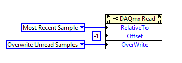
Alternatively, setting the following read properties before starting the task should work for most devices (if not, please let us know you are using):
Best regards
-
The control law of read/write FPGA on the loop of the root / the UI thread?
Hi all
As the title suggests, the read/write control FPGA, https://zone.ni.com/reference/en-XX/help/371599H-01/lvfpgahost/readwrite_control/, is on the loop of the root / the UI thread?
Watch, https://zone.ni.com/reference/en-XX/help/371361J-01/lvconcepts/multitasking_in_labview/, this would indicate as that, but I would get a good response.
Kind regards
David
While I'm not 100% if it acts on the loop of the root / UI thread - calls to the FPGA (e.g. control of read/write operations FIFO) block permanently. I remember having a weird problem in the past where my FPGA operations have been suspended because I was expecting given FIFO elsewhere.
You should be able to test this easily enough - try to open a file dialog during playback of your FPGA. If playback crashes while the dialog is open, you have a loop of root problem.
-
Modes of failure in TCP WRITE?
I need help to diagnose a problem where TCP communication breaks down between my host (Windows) and a PXI (LabVIEW RT 2010).
The key issues are:
1... are there cases where to WRITE TCP, a string of say 10 characters, write more than zero and less than 10 characters for the connection? If so, what are those circumstances?
2... is it risky to use a 1ms timeout value? A reflection seems to say that I won't get a timeout in uSec 1000 if we use a database of time 1-ms, but I don't know if this is true in PXI.
Background:
On the PXI system, I use a loop of PID-100 Hz, controlling an engine. I measure the speed and torque and control the speed and the throttle. Along the way, I am in a position 200 channels of various things (analog, CAN, instruments of TCP) at 10 Hz and sending masses of info to the host (200 chans * 8 = 1600 bytes every 0.1 sec)
The host sends commands, responds the PXI.
The message protocol is a type of variable to fixed header, payload: a message is a fixed 3-byte header, consisting of a U8 OpCode and a USEFUL of U16 load SIZE field. I flattened a chain structure, measuring its size and add the header and send it as a TCP WRITE. I get two TCP reads: one for the header, then I have the heading unflatten, read the SIZE of the payload and then another read for that many more bytes.
The payload can be zero byte: a READING of TCP with a byte count of zero is legal and will succeed without error.
A test begins by establishing a connection, configuration tips, and then sampling. The stream of 10 Hz is shown on the home screen for 2 Hz as digital indicators, or maybe some channels in a chart.
At some point the user starts RECORDING, and 10 Hz data go into a queue for later write to a file. It is while the motor is powered through a cycle prescribed target speed/torque points.
The registration lasts for 20 or in some cases for 40 minutes (24000 samples) and then recording stops, but sampling does not. Data are still coming and mapped. The user can then do some special operations, associated with audits of calibration and leaks, and these results are stored. Finally, they hit the DONE button and the mess is written to a file.
This has worked well for several years, but that the system is growing (more devices, more channels, more code), a problem arose: the two ends are sometimes get out of sync.
The test itself and all the stuff before configuration, works perfectly. The measure immediately after the test is good. At some point after that, he goes to the South. The log shows the PXI, sending the results for operations that were not opposed. These outcome data are garbage; 1.92648920e - 299 and these numbers, resulting from the interpretation of random stuff like a DBL.
Because I wrote the file, the connection is broken, the next test he reestablished and all is well again.
By hunting all of this, I triple-checked all my shipments are MEASURES of the size of the payload before send it. Two possibilities have been raised:
1... There is a message with a payload of 64 k. If my sender was presented with a string of length 65537, it would only convert a value U16 1 and the receiver would expect 1 byte. The receiver would then expect another heading, but these data come instead, and we are off the rails.
I don't think what is happening. Most messages are less payload of 20 bytes, the data block is 1600 or so, I see no indication of such a thing to happen.
2... the PXI is a failure, in certain circumstances, to send the entire message given to WRITE of TCP. If she sends a header promising more than 20 bytes, but only delivered 10, then the receiver see the header and wait more than 20. 10 would come immediately, but whatever the message FOLLOWING, it's header would be interpreted as part of the payload of the first message, and we are off the rails.
Unfortunately, I'm not checking the back of writing TCP error, because she's never not in my test here (I know, twenty lashes for me).
It occurs to me as I was him giving a value of timeout 1-mSec, since I am in a loop of 100 Hz. Maybe I should have separated the TCP stuff in a separate thread. In any case, maybe I do not get a full 1000 uSec, due to problems of resolution clock.
This means that TCP WRITE failed to get the data written before the time-out expires, but he wrote the part of it.
I suspect, but newspapers do not prove, that the point of failure is when they hit the DONE button. The General CPU on PXI is 2 to 5%, at that time there are 12 to 15 DAQ field managers to be close, so the instant the CPU load is high. If this happens to coincide with an outgoing message, well, perhaps that the problem popped up. It doesn't happen every time.
So I repeat two questions:
1... are there cases where to WRITE TCP, a string of say 10 characters, write more than zero and less than 10 characters for the connection? If so, what are those circumstances?
2... is it risky to use a 1ms timeout value? A reflection seems to say that I won't get a timeout in uSec 1000 if we use a database of time 1-ms, but I don't know if this is true in PXI.
Thank you
If a TCP write operation times out, it is possible that some data did in fact get placed in the buffer, and it will be read by the other side. This is why there is an output bytes written on TCP Write function, to determine what was actually put in the buffer.
To account for this, you can proceed as follows:
1. do an another TCP write and send only the subset of the first package that does not get completely passed. Use bytes written to Get String subset for the remaining data.
2. start with greater delays.
3. in the case of a timeout, the close link and force a reconnection so that the data of the partially filled buffer not get transformed by the other side.
Maybe you are looking for
-
How can I remove a message from iPhone 7 Awards test center
Facebook is frozen on my iPad, because I can't get rid of a message from the "Rewards Center" saying I was selected because they need more testers for the new iPhone 7. Press OK to participate and receive a 6s free iPhone. I know it's a scam, but h
-
Read an absolute encoder in cRIO 9076
Hello I try to use cRIO 9076 and NI 9401 to read an absolute encoder (http://www.gpi-encoders.com/PDF/A58.pdf). I hope that it is possible. Please can someone advise if there are any example or a tutorial that explains how I can deal with the digit
-
I recently did a reinstall of XP sp2 on this pc and I can't seem to update to sp3. I tried the suggestion of microsoft but that did not help... I seem to assignments and read but who can't seem to upgrade... Does anyone have a suggestion?
-
Hello I just bought a Deskjet 2544 and are unable to print on the project. I can't find it in the advanced settings. I can find levels of gray, but this does not remain on after I chose it. Is gray and the project of the same thing? Can someone tell
-
Original title: badminton MSGM8 phone to the USB port on my laptop to pis draft.exe connecting a phone to cricket MSGM8 USB on my laptop (running Windows XP Pro) run the Add New Hardware Wizard, trying to locate the software for Qualcomm CDMA Technol