Table of waveform and digital signal 2
Hello
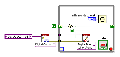
I need to see 2 or more digital graphic USB6008 of waveform input signal, but each signal must be different offset, it is possible?
Just add a constant offset to the second signal between the Boolean value to (0,1) and the fiber node.
Lynn
Tags: NI Hardware
Similar Questions
-
Could someone tell me how to convert the digital signals in table 1 d of digital waveforms
I use 9474 for drving an engine. for that I have uses 2 ports - to activate and another for running. These signals in the form of Boolean values. I am to convert these signals to a table and since iam doing a digital waveform. but when iam connecting these to the module 9474, it show an error "source is a digital waveform and sink is 1-d array of digital waveform... any body can help in these issueee please...»
Pop - up on the thread and choose Insert...
Build the table.
Ben
-
MyDAQ - generation of a digital signal and display on an analog waveform graph
Hello
I use the MyDAQ OR generate a digital waveform with a Frequency adjustable. This is implemented in a program, I already wrote it, which generates a TTL 'like' impulse out of the sound card. I display the result on a graph of analog wave form, and I would like to be able to display the digital signals generated by the myDAQ on the same graph. (Not in the same time, one or the other, activated by a button). I've been messing around with tables and conversions, but I can't really do with all this.
It's the vi, I did to generate the digital signal of frequency with MyDAQ. Any suggestions on how to do this if the following is false, would be great too, as I just got the MyDAQ a few days ago. I think there must be a better way, but it's the best I could come up with so far.
Hi Jonny,
The General logic, that you use to create a digital pulse train is very good. This VI you wrote should work and create the pulse train based on timing of software (which is fine because you have not DIO clocked by the material on the myDAQ anyway). However, it is generally advised to start the DAQmx task just before your time loop and then disable the task after the while loop when you press stop.
For reference, there are a few examples of good enough LV that I recommend you watch too much for this application. If you try just to create a digital pulse train, the example Gen dig Pulse Train - Continuous.vi is a good example that uses a counter to create a digital pulse of your desired frequency train. It is generally the preferred method to create a pulse train, if you have equipment available to do (the myDAQ there a meter). Otherwise, there are a few examples DIO who write continuously in a digital line / port.
If you are unfamiliar, you can find the examples by clicking Help > examples find... into LV then navigate to hardware input and output > DAQmx > generating digital impulses or the digital generation.
Also, here is some additional information on the myDAQ and its counters:
Hope this helps.
Chris G
-
Table 1 d of digital waveforms
I have a table 1 d of digital waveforms and I need to work with the data. I can't get the 'mass' to work with any function table or any other type of function also.
I need to be able to convert these so I can find a particular value in the table.
Thank you.
So you're just trying to get inside the matrix? Use a loop For or an Index Array node.
-
Pavilion p - 7 1287 c: sending digital video and audio signal from p-7 HP 1287 to HD TV
No HDMI output on the back of the computer. Ordered a KENIMBENI Pro VGA HDMI converter, VGA male to male VGA Cable and a cable of Y min stereo to 2 RCA. Kanex output VGA to convert HDMI is HDMI to the HDMI connector on the back of the HDTV (Viera by Panasonic). No signal on the TV. This motherboard or video card takes by taking a digital audio and video signal and send it to the TV. Obviously with the VGA of the monitor on the PC is turned off.
Previously, I had a cable HDMI to DVI and I had to awkwardly move the image on the monitor of the PC to HDTV, but with no sound. Should I return the material (Kanex VGA to HDMI converter and associated cables) at B & H so that I can always go back and get a refund.
Look forward to some potential solutions, wish this PC has HDMI output, would probably make this process much easier. First time on so I hope someone can help.
BC825 wrote:
..... Previously, I had a cable HDMI to DVI and I had to awkwardly move the image on the monitor of the PC to HDTV, but with no sound. Should I return the material (Kanex VGA to HDMI converter and associated cables) at B & H so that I can always go back and get a refund...
Hello
The following ports are on the back of your computer:
Figure 4: Rear i/o panel -
How do I configure other digital ports except port 0 of daq 6351 acquisition of digital signals
Mr President.
I can acquire digital signals using 8 lines of port 0, but I have to get the waveform Digital 24-bit. So please tell me how to configure other DIO ports so that I acquired digital signals using these DIO line also
You should be able to create a task DAQmx to read Port0, Port1 Port2. When you read the DAQmx data, you must combine the port if necessary data table.
-
Multichannel data acquisition and 2D signals
Hello
[Use of labview 2011 license academic with NI9234 and cDAQ-9178].
I'm trying to read, display and record the signals from two isotronic accelerometers and a microphone at the same time for future signal analysis (FFT, etc.). I wish to display data of vibration and noise signals in real-time at 44100 Hz sampling frequency and display a waveform of final sampling, which takes about 40 years. I would like to then write the data to a file.
The associated block diagram, attached vi. I could view real-time each accelerometer and sound using iterations of the loop and split the signal. Unfortunately I record three channels of data in a table unique 1 d-wave form. It seems that the data is saved as iteration1 (ch0) .iteration1 (ch1) .iteration1 (ch2) .iteration2 (ch0) .iteration2 (ch1)... and so on.
Although I could show all three signals separately in the waveform graph, but I prefer these data to save as table 2D-waveform (each channel in a separate column).
I believe that this issue has been raised here (http://ni.lithium.com/t5/LabVIEW/Concatenate-2D-data/td-p/873409) unfortunately no solution has been proposed. How can I record the signals of data acquisition in 2D waveform?
Thank you.
I think to represent vi attached a solution architecture producer consumer for the problem mentioned above. Just thought I'd share to those who can live a similar situation that I had been faced.
-
Several records of digital signals to PDM
I acquire several records of six 6561 cards. Why I can't write TDMS files, should I change the format to something the TDMS file will accept? What is the format that would be?
Has anyone seen an example of multi-check continuous acquisition? Is this possible? I want to get the number of records more that the amount of on-board memory can accommodate.
Right, I'm back!
Thus, the reason for which the string name of the input string becomes an input array when we wire in the Digtal waveform data is because the table of digital data in the cluster comprising its waveform creates a new string in the TDMS file for each row of data in the table. If the digital data has been compressed, you get always 1 channel per data line and an additional channel (the first string) for the command.
If all this you by gliding, and I wouldn't blame I had to reread several times myself, then I recommend you simply play with the vewier of TDMS files to get an idea of how channels are created.
I hope that this has proved useful. All the best with your LabVIEW work!
-
problem while conspiring waveform of the signal in real-time
Dear Sir
I use LabVIEW8.2 and USB1208FS for data acquisition. I have configured hardware with LabVIEW and data in real time using the Universal Library VI AInScBg.vi. When I draw my signal on the waveform (amplitude vs. frequency) then on axis x frequency ranges from 0 ~ 0.49 hz. I have change the sampling rate of 1000 Hz to 4000 Hz, but on the x-axis without frequency change occurs and it is set at 0.49 hz. Can you please guide me how can I get the frequency of my own interest on the x-axis.
I enclose you daughter of LabVIEW for reference.
Kind regards
Muhammad Irfan
Student
UTP Malaysia
0060149087570
Simply change the text label of the x-axis of frequency does not automatically the correct calculation. You do not pass in the sample information in the service spectrum, so you get no frequency information. You can see the strain on the entry point. The function expects a data type of waveform as input. Without it, the dt will default to 1. Then, use the function create a waveform and add information from dt to it as well as your table of Y.
-
How to draw a part of a digital signal
Hello, I have a digital signal, and I would like to draw just the 10 first or second 10% of the curve on a digital chart. Could you please help me on this. What is memory, and the effective, faster way to do this.
Thank you
Use GET subset of waveform:
http://zone.NI.com/reference/en-XX/help/371361K-01/lvwave/get_waveform_subset/#Instance7
There is a polymorphic digital version of it.
-
How to table of waveform of input 1 d in the lock with the amplifier
I have a LabView application that I have to change to include a lock in the amplifier. The application uses a capture card of data several times to capture a sample of 0.1 s of two signals (one signal, a single reference) in a laboratory test. Before the measure was made by the base RMS module to record the VRM in the signal, and the reference is ignored. However, the measures that I am now the scene run many s a lower and so I would use a simple RECS in the kit OR of.
I am happy (I think) with the configuration of GARLIC but I am struggling to understand the requirement of input data. It should be an array of 2D, with the identifited of reference signal. However, the output of the part of the utility that captures the waveform is a table 1 d of waveform. Could someone advise me on how to convert the table 1 d of waveform in a 2D table suitable for admission to the GARLIC?
As you may have guessed that I am a newbie to LabView, I try to modify an application designed and assembled by a former colleague, so I'd appreciate simple suggestions!

TIA.
You have separated for each signal waveform 1 d arrays, or do you have a 1-d single waveform chart where signals are separate items in the table? If this is the first, you should do something like the code below. If you have a single Bay, then the code would be similar - you could just use a table of unique Index function. You may or may not need to transpose the table 2D. I don't know what waits for the lock in Subvi - channel data by row or column.

-
time extraction of the digital signal
Hello
If I have digital signals from optical barriers and to extract the time (for a body that passes these 2 obstacles) how can I retrieve this day there using Labview.
THX
I have chata,
Thanks for the answer, and I hope that your well.
Here's an example I've done for a client, eager to discover the time of a flat section of its waveform.
In your case, you must make a detection of pic on both codes, then less locations and a few x with the number of the sample to get the time.
Let me know what you think.
Kind regards
James.
PS Sorry code is a bit hasty.
-
No digital signal to headphones Jack S/pdif - Satellite P100-227
I have the Satellite P100-227, I brought a lot of different types of cables and adapters for trying to get a digital signal to headphones s/pdif Jack (the manual says that the helmet and S/pdif share the same socket). I tried a cable optical toslink to an adapter optical 3.5 mm but I can't not all digital audio of this laptop. It seems strange that there are a lot of output video but not audio Digital 5.1?
Why can't they provide a daily normal production as an audio output optical digital toslink?
Hello Chris
I checked the specification for Satellite P100 - 227 (PSPA0E) and it is listed follow Note:
Audio Line out Jack S/PDIF - not availableGood bye
-
Synchronization of analog and digital output with the external sample clock
Hello
First of all sorry for my English, I will try to explain what I want to do.
I want my PCIe-6321 to send two custom signals (modification sawtooths) on a mirror controller. I would also like to generate output with my card at the beginning of each tooth of saw. Everything must be synchronized with an external k-clock signal of 100 kHz. The idea is that whenever the PCI receives a trigger to external clock, it sends two analog output voltages and when he received 1024 clock ticks it will also send a pic of triggering TTL. What I do is first prepare the map and after that in a loop sending and modifing the output values of the two signals and at the same time send a digital signal Boolean in each arch, so when's done it 1024 iterations of the loop I send an event to the digital port. Attached you can see.
The problem is that I don't know how to synchronize both. Can I use the sample clock just to the analog output? I can use sample for the two outputs clock, or do I need to use the output of the meter? If don't know how to use it here.
If I do nothing else bad/wrong, I would be grateful for feedback.
Thanks in advance,
PabloI don't know how but I find the solution. I'm generating more than a positive value (as I was triggered maybe very fast the oscilloscope has been absent there). If I put the sample clock of digital output to use the sampling/ao/Dev1 clock that it doesn't, but if I put to use the same source as the OD (terminal where my external clock is connected), but the trigger to start the DO to be Dev1/ao/StartTrigger this works. I don't really know why, but it does.
Thank you for your patience and your help. I put here the final code.
-
Table of waveform in time real Multi ground
Hello
I've attached a picture showing part of my code. What I'm trying to do is to create the exact waveform as "Cell pressure (kPa)", but in the x-axis in real-time. I created the "wave form" and that it does not work enough. This table will 'Y' to 'build the waveform"will contain 8 items and when I run the program,"Waveform"shows all the elements in a plot rather than in 8 different locations in a single diagram.
Can someone choose where I am doing wrong?
Thank you
Hoda
Hoda wrote:
Table of waveform isn't the time component. I need to show all plots on a graph and real-time
As you convert scalar data to a cluster to the chart, he has no information indicating the time. Missing time initial T0 and the dT for the time interval.
Outside your wire loop right now for the Xscale.Offset property for the graph node. Because your loop time is 1 second, you must set the DT. But if it was something else, you must set the XScale.Multiplier property as well.

Maybe you are looking for
-
my daughter has an opliplex xp gx620 counter top. they never ran VirusControl. now it hangs after starting upward and says he has many viruses, even to use the cd to look viruses.it says there is a virus attached to the driver for the cd drive. How
-
Rebooted Vista. Now old files, programs, etc do not work on this new administrator? I think so.
If my computer has problems. Finally I could access the black screen with options like the safe mode, normal mode etc. None of those working. He said that I had to reinstall vista, I still had the record of the purchase so I did. NOW, my documents, p
-
How can I get the images after the computer was recovered to a previous version?
I needed a previous version to recover a video. to do some of my images did not return. I put in my backup CDs, he had the previose photos to the backup drive. Now I need to retrieve other images, but don't know how.
-
where can I get the installation program for Captivate 8
I prepare a new replacement device for our customers. They currently have 8 Captivate. I have the license key, I can't find the installer of this version of Captivate. And/or my license key for 8 Captivate would work for 9 Captivate?
-
Como dress 0xc000001d? How to solve this problem?
No puedo open after fx cc 2015 nor first don't cc 2015, porque sale me "Adobe first Pro.exe: application no is pudo iniciar correctamente (0xc000001d)" Por lo than hay than t aceptar y is cierra.