MyDAQ - generation of a digital signal and display on an analog waveform graph
Hello
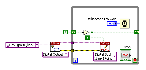
I use the MyDAQ OR generate a digital waveform with a Frequency adjustable. This is implemented in a program, I already wrote it, which generates a TTL 'like' impulse out of the sound card. I display the result on a graph of analog wave form, and I would like to be able to display the digital signals generated by the myDAQ on the same graph. (Not in the same time, one or the other, activated by a button). I've been messing around with tables and conversions, but I can't really do with all this.
It's the vi, I did to generate the digital signal of frequency with MyDAQ. Any suggestions on how to do this if the following is false, would be great too, as I just got the MyDAQ a few days ago. I think there must be a better way, but it's the best I could come up with so far.
Hi Jonny,
The General logic, that you use to create a digital pulse train is very good. This VI you wrote should work and create the pulse train based on timing of software (which is fine because you have not DIO clocked by the material on the myDAQ anyway). However, it is generally advised to start the DAQmx task just before your time loop and then disable the task after the while loop when you press stop.
For reference, there are a few examples of good enough LV that I recommend you watch too much for this application. If you try just to create a digital pulse train, the example Gen dig Pulse Train - Continuous.vi is a good example that uses a counter to create a digital pulse of your desired frequency train. It is generally the preferred method to create a pulse train, if you have equipment available to do (the myDAQ there a meter). Otherwise, there are a few examples DIO who write continuously in a digital line / port.
If you are unfamiliar, you can find the examples by clicking Help > examples find... into LV then navigate to hardware input and output > DAQmx > generating digital impulses or the digital generation.
Also, here is some additional information on the myDAQ and its counters:
Hope this helps.
Chris G
Tags: NI Products
Similar Questions
-
How to convert an analog signal into digital signal
Hello
How to convert an analog signal into digital signal, such that each sample of the analogue signal corresponding to 1.2V will be represented as '1' digital signal and other samples of the analog signal (which are not 1.2V) will be represented (converted) ' 0' in the digital signal.
And how to view the wavefroms or graphical indicators signals.
Thank you.
If you have 1000 samples and you want to convert to digital, you get 1000 digital values. Attached, that's what I mean.
-
How to draw a part of a digital signal
Hello, I have a digital signal, and I would like to draw just the 10 first or second 10% of the curve on a digital chart. Could you please help me on this. What is memory, and the effective, faster way to do this.
Thank you
Use GET subset of waveform:
http://zone.NI.com/reference/en-XX/help/371361K-01/lvwave/get_waveform_subset/#Instance7
There is a polymorphic digital version of it.
-
Merge the signals and waveform graph
Hi all
I ask you what follows, because I have little knowledge about labview
I have a function of merging signals which should take 7 signal as input. but I have no idea how to do to see the 7 signal on a waveform graph outputs. I want to show the 7 signals each of them on a waveform graph. (like research in the panet before I would see an array of unique waveform showing the 7 signals).
can you guys help me?
Thank you.
I'm confused for... Please find attached a really simple screw that does the job you want...
Are you tracing the curve of a graph or a chart? My VI control is a chart.
-
Generation of digital signals through external trigger pulse on PCI 6251
Sir I want by NI 6251 because I read it has the ability to generate and acquire digital signals on port 0. I want to know that can I generate external clock wave triggering (providing impulses to a line on the acquisition of data)?
Hi Ali211,
Yes, you can use a source of sample for the digital input/output clock external clock. You can connect the external clock source to one of the lines PFI (PFI0-PFI15) and specify the source clock sample like this outer line of PFI.
There are some shipping DAQmx examples that you can start with. Find the examples by clicking Help > find examples in LabVIEW.
DAQmx continually reading digital channel with External Clock
DAQmx channel External digital writing Clock
Hope this helps.
Chris G
-
How to read and display a my a miccrontroller (MCB1700) on labview signal connected via a port on a machine PXI CAN?
I tried using a DAQ Assistant, but the port is not included as one of the physical channels supported, even if all his drivers are up to date.
Help, please...
Thank you.
If you can read it in MAX, then you should be able to run the NI CAN example.
Help-> find examples
Find the CAN and watch CAN Receive.vi.
Basically, set up the network, open the object, read in a loop close object when it is done.
If you have any questions about the example, go ahead and post your vi and we can work from there.
-
Pavilion p - 7 1287 c: sending digital video and audio signal from p-7 HP 1287 to HD TV
No HDMI output on the back of the computer. Ordered a KENIMBENI Pro VGA HDMI converter, VGA male to male VGA Cable and a cable of Y min stereo to 2 RCA. Kanex output VGA to convert HDMI is HDMI to the HDMI connector on the back of the HDTV (Viera by Panasonic). No signal on the TV. This motherboard or video card takes by taking a digital audio and video signal and send it to the TV. Obviously with the VGA of the monitor on the PC is turned off.
Previously, I had a cable HDMI to DVI and I had to awkwardly move the image on the monitor of the PC to HDTV, but with no sound. Should I return the material (Kanex VGA to HDMI converter and associated cables) at B & H so that I can always go back and get a refund.
Look forward to some potential solutions, wish this PC has HDMI output, would probably make this process much easier. First time on so I hope someone can help.
BC825 wrote:
..... Previously, I had a cable HDMI to DVI and I had to awkwardly move the image on the monitor of the PC to HDTV, but with no sound. Should I return the material (Kanex VGA to HDMI converter and associated cables) at B & H so that I can always go back and get a refund...
Hello
The following ports are on the back of your computer:
Figure 4: Rear i/o panel -
How to generate 3 Wick using digital signals
Hello
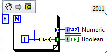
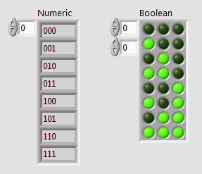
I am in the course of generations bit 3 digital using 9403 digital module and cRIO 9014.I signal must generate all combinations from 000 to 111.la so I have to give the Boolean constant either true or false 9403.I output module'm not gettimg how incrase step value of 000 001 and so on... Should I use the shift register?
I know how to use the registry to offset for integer value bt I don't hv any idea on the Boolean value.
in the hope of solution...
Here is a small example that uses the number to array of Boolean function. The digital indicator has its display of the binary value (%b) formatting.
-
2 digital signals keep using pxi 6544
Hello
I wonder how I can generate 2 digital signals that continues and I will able to make even phase, or different phase 1/2, or 1/4 different phases. And I need them to be able to their output in any channel (free) my PXI 6544.
I've seen examples of generation (no script), but most of the examples shows just how to generate data in parallel. Generating script I use to achieve this? Repeat for the thing?
Kind regards
Yan
-
No digital signal to headphones Jack S/pdif - Satellite P100-227
I have the Satellite P100-227, I brought a lot of different types of cables and adapters for trying to get a digital signal to headphones s/pdif Jack (the manual says that the helmet and S/pdif share the same socket). I tried a cable optical toslink to an adapter optical 3.5 mm but I can't not all digital audio of this laptop. It seems strange that there are a lot of output video but not audio Digital 5.1?
Why can't they provide a daily normal production as an audio output optical digital toslink?
Hello Chris
I checked the specification for Satellite P100 - 227 (PSPA0E) and it is listed follow Note:
Audio Line out Jack S/PDIF - not availableGood bye
-
Simulate the sine wave using LabVIEW FPGA with NOR-myRIO and display in real time
Hello
I'm relatively new to LabVIEW FPGA. I am trying to test (and later apply) controllers high speed on myRIO.
At this point, I'm trying to simulate the sine wave from 1 to 10 kHz using Sinewave generator VI express. I also intend to display the sine wave on the time real (RT) using FIFO. However, I had a bit of trouble to understaing various synchronization parameters.
1. how to encode information about the sampling frequency generating sine wave? (The side FPGA vi requires only the frequency of the signal and possibly phase and does not rate update lines)
2. how to estimate the number of items in a FIFO? (that is, the relationship between the rate of updates to loop (RT), the signal frequency, sampling frequency and the number of items in the FIFO)
It would be great if we could share a very simple program (side host and target) that did something similar.
Thank you
MILIN
Milot,
I think the problem is the type of data in your FIFO. Your FIFO is configured to use a data type of I16. The problem is the number, it displays only ever will be-1, 0 or 1. To resolve this problem, you must send the sine wave as a fixed point data and convert it to a double on the side of the RT. This should significantly improve your resolution.
-
frequency of the digital signal 6009
Hello, how to generate the digital signal with frequency 50 Hz using NI USB-6009?
You can take a look at this:
Can I use a generation of impulses with the counters on the USB-6008/6009 case?
-
How to display the signal on a waveform graph in Labview Signal Express?
Hello
I want to display a signal in Signal Express 3.0 in a "waveform table", but don't know how to do it and I think that it may be impossible?
In Labview, there are two ways to view data, a 'waveform table' or a 'waveform graph. The great thing with 'picture of waveform' is that it allows you to set a length of history and you can see the data move to the left (option graphic strip) that samples are recovered. It works perfectly.
In Signal Express I can only select "Graph XY" or "Waveform curve" by doing a right-click of the mouse, but I can't select "table of waveform. Is it really true that it is not possible to view data in a graph of waveform "with Labview? (1 analog signal during streaming, 100 samples to read at the rate of 1 K)
Thank you in advance,
Enrique
Hi Enrique.
You are right that there is currently no graphic waveform in SignalExpress. The thing nearest you can join, is saved data under a log and then he looks one when recording (which I know this isn't quite the same interactive behavior).
For your last comment, you wrote 'waveform curve', but I guess you meant 'picture' here as well.
Sorry about that. We recently received this request, then perhaps in a future version.
Phil
-
Digital input and output problem
Hello:
I do a test for digital i/o:
for a table of the digital signal to an output of data acquisition in the digital input to detect the output signal.
(bascially, it's like a loop that goes outside the material)It's pretty simple, as shown in the attached fichier_1.
It works well.
The manual light switch controls, which means that inputs and outputs are ok.Then I went on the low level DAQ for better speed, as in attached fichier_2.
But it does not work. Especially when I pressed stop to abort the loop, an error has occurred:To speed up, I went to the low-level data acquisition as the fichier_2 attached.
But it does not work. Espeically when I press the "stop"button to exit the loop, the error occurs.Possible reasons:
Requested value is not supported for this property value.
The value of the property may be invalid because it is in conflict with another property.Property: SampTimingType
Asked the value large clock
You can select: on requestI don't understand why the sampling time has a conflict here.
(It is probably just something very simple in data acquisition, but I checked a few examples and did not find a clue).
Hope someone can give me a suggestion.Ultimately, my goal is to make the attached file_3.
In this one, I generate a digital output, and then lead to the entrance.
Then I can take it as a signal to trigger my other task.Note:
I use a similar conti signal to control one of my camera.
I need to sync it with my another task.
So I think to generate a digital output (which share the same clock as the signal similar to the data acquisition device), then put it in one of the digital input.
By detecting this digital input, I can trigger my task and synchronize with this signal similar.
My camera's USB-6211.
I am aware of the latency of USB, but once the value is a constant value, then the synchronization is always good for me.
Actually, I was using an analogue at the entrance of the to do it before, it may work, but the synchronization error is too big for me.
I need to do some calculations/judgment for this analog value, which makes the time difference varies.
So I'm trying digital entry now and I hope that the digital input can trigger my task with a stable latency.Thank you very much
Have you looked at the specs? It clearly states that the digital I/o is a programmed software. You have not any hardware clock at all. The best rate that you could possibly achieve is around 1 kHz and which would have a considerable jitter the nature of non-determimistic of windows.
-
LAbview program behind schedule and displays the data arriving more than two minutes ago
I am currently using two OR 6070e daq cards PCI (16 analog inputs on one) which are syncronised in the software. In the producer I loop gain of 32 channels data and do my processing on the data in the loop of the consumer. Each signal is displayed on a waveform graph. I have sample at 32 kHz to my problem is that my software works well, but it lags behind in the necessary time sto updated graphics. More I run the software becomes more lag. For example, data showed the field of waveform if poster both 5 minutes after the due event. Even if I use a lower sampling rate (3 kHz) continues to accuse software. The number of samples, I've read is always a second of data. How can I make this software performing near real time with out such a big lag. I need to run my software on a windows OS. I know that you won't get no hard real-time running labview Windows OS, what can be done to improve the speed of my program.
1. another question on the data sheet of the data acquisition card NOR 6070e PCI indicates the size of the buffer FIFO is 512 S. Why can I in labview set myh size buffer to a value greater than 512 samples. For example when I taste 1000 Hz and read 1000 Hz off buffer I exceed the isze of buffer FIFO data acquisition card, but my program still works.
Cordially (sorry for the spelling error typed this quickly)
the main VI is DP_software
You do not have something interesting to look at.
Maybe you are looking for
-
Update graphics card intel HD for G62?
I have a G62 450sa with i3 370 m 2.4 GHz so I know it is one of the models later, I just want to know if I can open it and pop into one of the ATI cards that are listed in the replacement parts PDF. He said only 1.1 but I noticed that there's various
-
No audio output because High Definition Audio Driver cannot start (Envy 17 Quad) HDMI
Since I bought this laptop two months ago, the HDMI audio has always been inconsistent. I remember working once or twice, but there were several times when my audio driver recognizes that an HDMI cable is connected. Yes, I tried everything that is ob
-
original title: how to connect to the xp computer I have a Windows 7 and a xp pro Office (which I would like to act as a server). I would like to be able to access the files remotely. I wanted to see if I'm able to do this with desktop connection r
-
Window updates fail, keys corrupt registry patch, (Kb265370) and (KB2656353) failed
I used the fix it tool and discovered that I have a problem of "KEY of REGISTRY PATCH CORRUPT" can someone tell me how to solve this problem. Every time I try to install windows updates .NET Framework 1.1 (Kb265370) and (KB2656353) failed!
-
When you start Windows XP Professional I get warning no. firewall is enabled.
For about a week now when I start my computer at the bottom of the screen I get this message "your computer is perhaps in danger that no firewall is enabled. Click on the bubble to solve the problem. By clicking on the bubble I get Security Center, w