Tecra S3 clocked 100% intermittently
I had this problem about 1-2 times a day where the processor will hit 100% and stay there until I restart my laptop. I checked the Task Manager and IEXPLORER. EXE was sitting on 99% CPU usage.
I have the latest version of the BIOS, but don't know too what else it could be like any other applications where it is like running in the processor. Does anyone have any ideas of what it could be and how to stop it? BTW I recently ran a recovery and reloaded all my data and applications. (Still a lot of HARD disk space!).
See you soon
CG
Hello
The IEXPLORER.exe is part of Microsoft Internet Explorer.
I studied a bit on the Toshiba support site and knowledge base:
There, I found this article:
Internet Explorer freezes or responds slowly
http://support.toshiba-tro.de/KB0/TSB6701I80004R01.htm
I put t know if it will help you to solve the issue of the use of the CPU, but you could try it.
Tags: Toshiba
Similar Questions
-
ProBook G3 450: Time assets 100% Intermittent drive with 0 kB/s read/write speed
Hello
I am facing an active time for intermittent drive 100% with 0 kB/s reading or writing speed with my G3 450 ProBook running on 10 to win.
Meanwhile, the laptop does not. This effect always lasts exactly 60 s (visible in the Task Manager), and after that, the hard drive still responds once. Looks like some kind of timeout that happens after 60 seconds before returning to normal behavior. Sometimes the 100% active time occurs every few minutes and sometimes I can work for hours without interruption. So far I was not able to trigger the effect.
A Google search on "100% active time" returns a lot of suggestions like disable the superfetch, windows search, and the background intelligent transfer service. None of this solves the problem. The hard disk drivers (Toshiba) and the (Intel) SATA controller are up to date. I already reinstalled Win 10 who do not help either.
I have another problem with this ProBook. I don't think that this is related to this problem. However, you never know...:
I'm out of ideas. Any input is highly appreciated.
Thank you
Martin
Well, in the meantime, I found a solution... I bought a new HARD disk that is supported to win 10. It's a little embarrassing that HP sells the laptop with Win 10 and it does not work as it should. But anyway: problem solved.
-
How to get a regular clock (100 MHz, 10 MHz to 20 MHz) of the NI 4462 PCI?
Is it possible to extract a regular clock, high frequency of the 4462 OR?
I need to synchronize with another card (a PulseBlaster), which requires a 100 MHz clock: every card can be the main source, but they must stay perfectly synchronized.
(Both cards have on-board crystal oscillator modules of 100 MHz; one of the PulseBlaster is nested, would be so easy to connect a source external intead)
I use the PCI version, so the star PXI 10 MHz clock is not available. The 10 MHz or 20 MHz clocks that DAQmx usually exports seem not to be available for routing on this device.
I can't use the Sampleclock, because it is variable (~ 25.6 MHz, changing with sample-freq) and because it is not active when the 4462 is actually measurements.
In addition, this clock must be either 100 MHz, or a whole simple fraction of it (e.g. 10 MHz, so that a PLL can re - generate the 100 MHz).
At the present time, the best option seems to be to solder on the 4462 output pin quartz oscillator - but it's a really ugly way do... has anyone had an experience to make relevant changes?
Is there a better place to connect to? I would prefer to use the RTSI bus connector, but despite tempting advice in the documentation, it seems not possible to get out of the 10/20 MHz master time base: there is
an axis called RTSI7/RTSI_OSC, but it is a permanent decline.
Thanks for your help.
Nick Dear,
Thanks a lot for your help. As you say, this confirms what I already knew.
But we really need keep everything in harmony. So, here is what I did, which should hopefully help someone else in the same position.
The circuit is very simple, using a FIN1001 LVDS line driver. It is a SOT-23 package. Connections are the following:
* Din connects to the output of oscillator 100 MHz (TC0-2104, pin 4).
* Gnd connects to the Earth (C210, lower)
* + 3v3 connects to the more accessible place, that TCO-2104, PIN 6. [The 3V3 regulator is on the back of the map]
* FIN1001 food is decoupled with a 0.1uF adjacent capacitor.
* Dout + and Dout-are connected to a short (30cm long) of the unshielded, twisted pair made of wire 0.7 mm PTFE. (Z ~ 110 ohms)
Photograph is attached. The SOT-23 package is physically secure, with a tiny drop of cyano, C210 and mounted on his back.
The receiver uses a FIN1002 receiver, finished with 100 ohm twisted pair and uses a 74VHC04 to convert 3.3V 5V TTL.
It is mounted on a 14 pin DIL socket, to plug directly into the socket on the other card PCI which normally has its own oscillator module.
Result: everything works, and I have a 100 MHz clock available to drive the other timing card.
-
Tecra 9100 comes on intermittently and turns off after 10-15 seconds
Referring to a Toshiba Tecra 9100, model No.: PT910E-602SF-FR
The power button normally doesn't light up at all, even if sometimes it starts normally, starts to load windows, then always turns off after 5 to 15 seconds in any case.
It always requires the batteries very well, but it won t turn on. I ve checked the ram, hard drive and I re - set the default bios - nothing prevents to cut if you can get it to turn on.
Any ideas what could be the problem? Any help appreciated, it s the second time I had - the same problem the last time!
Thank you
Hey,.
Have you already tried to clean the fan? Maybe a lot of dust blocking the fan for laptop can start t, and then turns off itself due to a higher temperature. It would be interesting to try to clean it.
But in my opinion, you've done everything you can do, and it looks like a malfunction of the motherboard. If cleaning using fan doesn t I think the motherboard is faulty or something else. If you are familiar with the disassembly of the laptop, you can try to fix it yourself with second hand parts. Otherwise it s time for a new laptop I think
-
Tecra S1 clock not to mention when it is off
I have a Tecra S1 laptop. The time does not count when the computer is turned off. So if I stop at 15:00, the time still says 15:00 if I turn it on 4 hours later.
Whenever I connect to it at work, the time is updated by the scripts for logon to work for synchronization with servers. However, when I do dial-in (90% of the use of this machine) the scripts do not work, and that's why time is not synchronized with servers.
Does anyone have an idea? I guess that this is related to the dead CMOS battery, but I don't know where it would be. Do these machines have a CMOS battery? If so, how do it?
Hello
I don t think that the RTC battery is defective. If the battery would malfunction, then you should see a message on first boot. Also the data and the time would set the default value.
In your case I think that it of a software problem and you must check if Windows time service is enabled.
-
My specs are:
-Chasis SMU-1082
-FlexRIO SMU-7962R
-MRF custom calendar card
The MRF pushes its clock to the PXI_CLK10_IN with own clock at 10 MHz.
I use several SCTL to Council FlexRIO with multiple clock sources. Availiable clock sources are (also see attachment):
-40 MHz on-board clock
-PXI CLK10
-Clock 100 MHz
-Clock 200 MHz
-Clock DStarA
I can't get my hands on the information what are the sources of clock of 100 MHz and 200 MHz clocks. Who are special oscillators to the Board of Directors? Are the clocks 40 MHz clock PLL - ed or the PXI CLK10 PLL - ed?
After some additional searching on Google, I got my answer: http://zone.ni.com/reference/en-XX/help/372614J-01/target5devicehelp/pxie_base_clocks/
-
cDAQ HAVE task using external clock
Hi, I am trying to use a clock signal on a line of PFI in order to generate a clock, but at a lower rate, for a task to HAVE. I run into many issues that I can't explain.
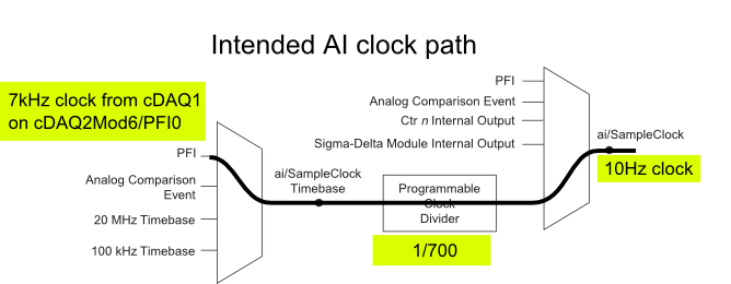
I have a cDAQ-9172 with an entrance module analog (9225) in the Groove 3 and a digital input module (9411 - 2 MHz DI) into the slot 6 (where the PFI lines are accessible). I want to use an external signal on et0/PFI0 to act as the clock for an analog input on the 9225 task. This signal comes from the cDAQ anothr chassis and is too fast for the task to HAVE it, so I intend to use the time base entrance and the divider to clock (as shown on page 31 of the cDAQ-9172 manual). See picture attached for a graphical representation of my problem.
If I have the wiring from the signal "/ cDAQ2Mod6/PFI0" in the DAQmx timing VI, get the error 200414 saying that "required sample clock source is not valid." It is strange because it is listed as "Direct route" in Max (the VI of polymorphic DAQmx Timing is configured as 'Sample clock') Q: why this route is not suitable for the task?
If I use DAQmx Timing property node and change the Source 'Sample clock Timebase' to ' / cDAQ2Mod6/PFI0 ", the task starts without error, but the separation seems to be forced to 256. If I try to change the properties of the separation of the time base, I get error-201100. Try to change the 'sample clock rate"doesn't have any impact on the task and the remains of divider"256 ". Q: why the 'Programmable clock divider"locked to 256 when using the PFI line or can you just not program directly?
I came across another error is the minimum speed on the PFI line. If I have the wiring (for the SamplClock Timebase) lower at 1 MHz, LabVIEW returns error-200077. The error message indicates that the minimum value is 1 MHz. 9172 manual shows the clock 100 kHz is an option for the time base, certainly less than 1 MHz. Q: What are the limits of upper and lower frequency for a clock signal on the line PFI for the ' Timebase AI/SampleClock "?
I looked on the site and in the DAQmx documentation for further explanation, but I have been unable to explain these strange behaviors. What are the barriers to entry of Timebase PFI and the time base "Programmable clock divider" preventing me to reach my goal here? If I can't do it directly, can I use the PFIn signal to feed an internal counter (to act as the clock divider) which could then generate the clock WAS at the rate I want? This method would allow me to perform a division arbitrary clock (unlike the ' 256', which seems to be forced on the PFI as a Timebase SampleClock.)
Finally, something seems odd that I can make an acquisition to 10Sa/s max but when I start a task using an internal timers of the cDAQ9172 and ask a 10Sa/s rate, the task really gives me a rate of 1612.9 sample/s while using the 12.8 MHz clock and a divider 7936 timebase. Q: Why can't the task to 10Sa/s?
I use DAQmx 9.7.0 and LV2012 SP1 (and I tried with 9.7.5 but I got the same results)
Thank you
Olivier
I got additional help Friday in another engineer at NEITHER and the solution to my original problem is actually very simple to get the clock from an external source path:
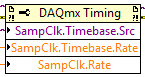
The idea of picking a PFI line for the basis of 'time' and the 'Programmable clock divider"(in fact, DAQmx calculate this number based on"HAVE sample time clock"and"Sample clock HAVE") works by using the node property below:
(SampleClock.Source cannot be resolved until the task is clerks/reserved, but the default option seems to be the time base that works well in this case.)
The question that I described earlier with the 9225 comes the module properties and the fact that it is a "Module of Sigma - Delta". That the module usually generates its own time of 12.8 MHz base clock (page 14 of the document 9225 # 374707) and the clock divisor is much less possible values than the other modules (must be a multiple of 256). It may use a different time basis from a PFI line, but it must be between 1 MHz and 13.15 MHz.
So a main clock between two chassis and tasks running at different rates of sharing should be easy and simple with most of the modules. With AI modules with Sigma-Delta converters add additional limitations and the master clock for the time base frequency must be selected to accommodate these module as well.
Another good news is that the Simulator seems to bear all these details and DAQmx (9.7.0 in my case) generates the same errors when you use a simulated chassis if you use real body. Play well!
-
Hard, I try to find a solution how to use external ABZ, quadrature encoder pulse to retrigger and clock repeatedly the same AO signals (and). A and B legumes should clock AO and Z-pulse wave should restart the wave early. Is this possible with card 6221? Can provide you the code example?
I use LV8.0
Thank you
Kevin,
Thank you for picking up the thread.
I understand your example and I already had working direct synchronization of the AO and MAKE the waveforms using external impulses. The problem is that my application cannot invoke the correct number of A pulse will run same waveform for months. I have to use Z-pulse to maintain synchronization in the long term. That's why the task should be redeclenchables.
I have made some progress since yesterday on the use of the example attached 'retriggerable_ao - NOR .vi' and the decoder external t.i. IC, which has transformed two 1024 A, B encoder in dish 4096 pulses/turn. My CO task then divides this frequency to 1024 (4 points per period). This regime of AO - redeclenchables DO so usually seems to work.
The problem now is that this chip must have a clock (~ 100 kHz or more) to work, and I don't want to build generator external too.
Y at - there no way to get all the signals of high frequency signals (100 kHz, 20 MHz or 20 MHz base time) USB-6221 Board any PFI available pine asuming that all of my commitments in Task-resource in this example are needed?
I tried a lot of things yesterday, but all the clock signals are either committed or roads are anavailable. I don't understand why I can't tap into it?
Any thoughts?
Mikhail
-
CPU upgrade for Satellite Pro A10?
Toshy A10 my wife has a Celeron 2.2 CPU. Can I get a faster processor?
Belarc gives details of 'primary circuit' as:
Tip: TOSHIBA Portable PC Version A0
Serial number: $$ S238Q23F
The bus clock: 100 MHz
BIOS: TOSHIBA Version 1.30 02/09/2003768 MB of RAM is installed.
Thank you.
Steve
Hello Steve
If you Google a bit you will find some A10 units come with Intel Celeron 2.5 GHz processor. Maybe you can use it to upgrade.
Speed of the bus on this unit is 400 MHz. -
Timestamp of photon arrival times
I would like to make a measure of cross-correlation of two photons. Auto hardware correlators and crossed correlators are available, but expensive. It seems that many other users resulted in the idea of using the 80 or clocks 100 MHz in the counter of entry for each desired channel, starting the counters at the same time and get every channel of photons in the door of the corresponding counter. Each photon triggers so the meter to store the total of the clock in its internal register, that is, the time stamp for this photon. Since then carries on a 32-bit counter clocked at 100 MHz only occur every 42 seconds, and average rate of photons will be at least 100 Hz, excesses should be easily recognized and corrected in post processing. So assume that all we have to do is get meter reads in a buffer. Bursts of photons with separations of arrival can be as small as few clock cycles. Average rates may be a few hundred kHz or more on each channel. We can adjust this rate by turning the power of the laser to the top or to the bottom - the source for the broadcaster that produces the stream of correlated photons. I suspect many others would like to know which system is better for these types of measures, the 6602 or the X-Series. If FPGA is a good solution, perhaps we should start a new thread about it. But for 6602 or X-Series: what is the fastest, it can do so for short bursts (speed for how long) and what is the sustainable rate? I realize that the sustained rate will depend on the material. I thought I only saw that the PXI beats the PCI bus in this type of application. PXI versions are better? In particular, what are the effects of the FIFO 128 sample on the X-Series compared to the 2 on 6602 buffer solution. And I noticed something about the speed of the front end for these two choices could be a problem in this regard. Pulses (photon) TTL on the door will have a width of 10 to 50 nsec.
For the flow of the series X is going to be much faster than the 6602 mainly due to the FIFO aboard (but PCIe gives more throughput than PCI). PCI or PXI should have the same flow (and PCIe vs SMU would also have the same flow).
Forum user (and NOT used) Andrew S displayed some X series streaming of references here. On a single meter, it was able to maintain the sampling frequency of ~ 20 MHz on PCIe X Series and ~ 8 MHz on USB of the X series. 6602 benchmarks are much lower, somewhere between 200 and 300 kHz (although the system used for benchmarks is old enough).
The 6602 allows shorter pulses that the X series. The specifications page indicates a minimum of 6.25 the 6602 ns pulse width. I saw a specified number directly to the X series in fact. X series devices include a maximum external base of 25 MHz clock frequency, which assuming duty cycle 50% would be 20 ns high and low times. 50 nsec would certainly long enough of a pulse, but 10 ns * could * be pushing. You will probably need to do some tests to confirm or not the X series is able to detect all the impulses for your configuration - if not then I would suggest the X series (PCIe-6320 is the lowest cost one) on the 6602.
Best regards
-
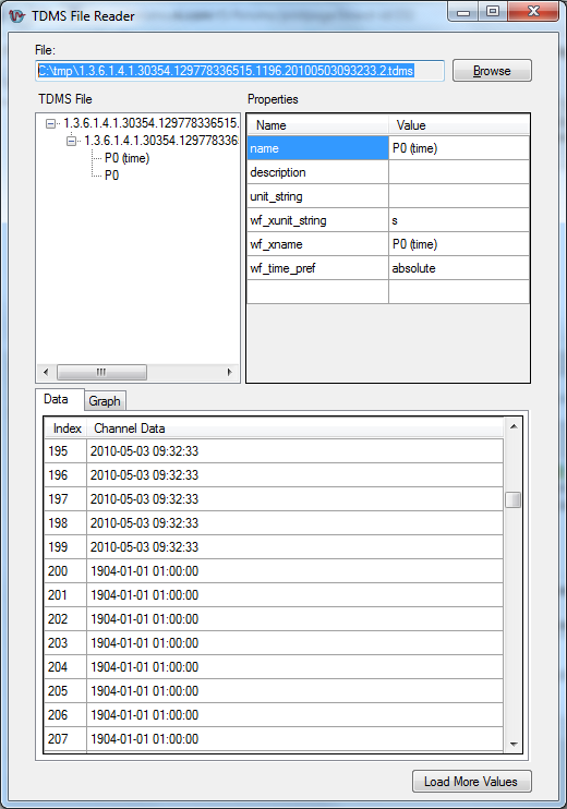
PDM file with automatic backup on corrupts the data.
When I test data stream into a file to PDM using AutoSave = true, data is corrupted in the 'package' #3 and beyond.
I write matched double/DateTime data to a TDMS file configured as TdmsWaveformLayout.PairedTimeAndSampleChannels.
When I try to read the PDM file, for example using the sample application to drive, I get all sorts of errors. Notably, the number of timestamps is not equal the number of samples (values y). More data is corrupted. In other words, the timestamps are invalid and the sample data is essentially random.
This happens every time I write the third package/lot and beyond. If I write a single sample, followed by another single sample, the third will be corrupted. If I write 1 kilosample, followed by 1 kilosample, sample no. # 2001 will be corrupted.
I guess that something is very wrong in the automatic backup routine, as data are always written correctly when I explicitly save the PDM file.
It's using MS 8.9.0.246 in Visual Studio 2008 SP1 using .NET framework 3.5 SP1 on Windows 7.
The TDMS file is created in the following way. Note that AutoSave is set to false to avoid the bug.
Every 10 ms, a double array [100] happens (with information in a DateTime table clock [100]). The data is stored in the file TDMS in a simple way:TdmsFile f = new TdmsFile (tdmsFilename, new TdmsFileOptions (TdmsFileFormat.Version20, TdmsFileAccess.ReadWrite, true, TdmsByteOrder.Native));
f.AutoSave = false; Must not be set to = TRUE because of a bug in Measurement Studio!TdmsChannelGroupCollection channelGroups = f.GetChannelGroups ();
ChannelGroup TdmsChannelGroup = new TdmsChannelGroup (...) Unique ID...) ;
channelGroups.Add (channelGroup);f.Save (); Needed when AutoRecovery is set to false.
TdmsChannelCollection tdmsChannels = channelGroup.GetChannels ();
foreach (IDicomInstance instance in series. Instances)
{
tdmsChannels.Add (new TdmsChannel (string. Format ("{0} (time) ', for example.") Signal.Name), TdmsDataType.DateTime));
tdmsChannels.Add (new TdmsChannel (string. Format ("{0}", for example.) Signal.Name), TdmsDataType.Double));
}
channelGroup.WaveformLayout = TdmsWaveformLayout.PairedTimeAndSampleChannels;AnalogWaveform
wf = AnalogWaveform . FromArray1D (sample. Data.Samples);
WF. Timing = WaveformTiming.CreateWithIrregularInterval (sample. Data.Timing);
WF. ChannelName = sample. Source.Name;
WF. UnitDescription = sample. Source.UnitOfMeasurement;ChannelGroup = _tdmsFile.GetChannelGroup (... TdmsChannelGroup Unique ID...) ;
TdmsChannel channel = channelGroup.GetChannel (... channel... name);
channelGroup.AppendAnalogWaveform(channel, wf);
channelGroup.Parent.Save (); Needed when AutoRecovery is set to false.This is what the TDMS file looks like in the sample player application:
For those who can run in it before we are able to get a fix on, a viable solution is to turn off auto-save and save the TDMS file any time a change to the file is made manually, such as after adding channels or groups, or write data. This will not negatively affect performance, because that's exactly what the property of automatic backup.
It should also be noted that this problem arises when you use the layout of the TdmsWaveformLayout.PairedTimeAndSampleChannels waveform.
I'll post back later when we have a fix for this problem.
Sorry for the inconvenience that this may cause,
NickB
National Instruments
-
HP Officejet 4500 G510g-m it not install full feature driver software w/Solution Center
I work for four days, try to install it, once again, my Officejet 4500 full package. And the frustrating thing is that the installer says that all of the software, with the exception of imaging and web printing, is installed. This includes the Solution Center. Yet, the center of Solution is not found anywhere else on my system.
I work with a Windows 7 Ultimate A55MH; 2.90 GHz AMD A8 - 3850 APU with graphics card Radeon HD;
cache 512 KB memory primary; cache memory secondary 4096 kilobytes; Tip: BIOSTAR Group A55MH
The bus clock: 100 megahertz; UEFI: American Megatrends Inc. 4.6.4 10/04/2011.2479.86 GB drive hard usable capacity
1149.13 gigabytes of free disk space
ASUS DRW-24B1ST c ATA Device [scanner]
ATAPI iHAS124 D ATA Device [scanner]
Portable Seagate USB device [hard drive] (500,11 GB)
ST3160815AS [hard drive] (160,04 GB)ST500DM002-1BD142 [hard drive] (500,11 GB)
WDC WD10EALX-009BA0 [hard drive] (1000,20 GB) - Windows 7 Ultimate disc...
WDC WD3200JS-22PDB0 [hard drive] (320,07 GB).
There is no reason that my system should not be qualified to run this printer/scanner and all software fair that goes with it. So, what, according to you, is the question? Is it me, or is this HP? Please, be honest with your answer...
Hi djbillyd,
Thanks for letting me know that the printer installed correctly on other computers.
Follow this post from @SuperMario1 to remove the printer files from the registry.
Driver HP deskjet D2300 series does not not in windows 7.
It's a different model, but it provides instructions to dig dip into the registry and get all of the HP software from the system.
You can also run the Microsoft Fix it Tool to the problems that programs cannot be installed or uninstalled.
Let me know the results.
Thank you.
-
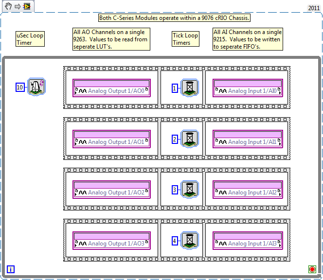
I can here sample 9215 channels separately sometimes differ by a few FPGA ticks?
Howdy-
The image below is a raw illustration of my question. I would like to individually explain the delay between excitation and response of 4 separate systems, each connected to a single channel of a 9263 (excitation) and a 9215 (response). The minimum time of update on both modules is approximately 10 uSec, so I think it would work if I just wanted to read all channels to HAVE at the same time. However, I did not yet understand internals of the 9215 that enough to know if I can taste the individual channels separated sometimes by a few ticks to FPGAS.
Thank you all, and have a great day.
Hi, BCRO,.
With the 9215, all separate channels separated from a/d converters, but still work in the same clock 100 kHz (10usec) that the module is limited to this sampling frequency.
So, in your case (thanks for the picture, by the way - it is always useful!), what will happen is that all four of these input channels of the 9215 will take place on the next loop cycle instead of staggered in one iteration of the loop.
For example, if you were to use a loop rate (25 kHz) 40usec, you can compensate for these delays at intervals of 10usec and that this configuration works, but not as quickly as you want.
I hope that this explanation makes sense, but the short answer is that we will not be able to do so during the execution of the loop in the time of minimum cycle.
-
Dear community,
I'm fighting a problem with the start of a task is triggered counter.
environment:
-Card: USB-6218 offer using the NOR-DAQmx driver last 9.7
-OS: Windows 7 x 64
-platform dev: MS Visual Studio 2010 (C/C++ language)... but don't mind if someone comes up with a solution of Labviewconfiguration of the card:
- redeclenchables counter 0, which begins to generate an amount over of clocks (100 to 1000) to pre-defined, high frequency (200... 250 kHz) when it receives an front amount on PFI0
-Counter 0 generates the sample clock for two analog output channels (AO0 AO1, number of samples is finished because finity of generated clocks)
-Counter 0 is also output to standard digital pins (PFI 4 / P1.0) and then smoothed (creates high constant on "clock" constant low orr on "no clock")process:
-NI DAQ card starts the output on AO, 0 and 1 for a predefined period
-While the clocks are generated, my most smooth guard PFI 4 high
-When the build is finished, the output of the smoothed counter 0 generates a falling edge (from 'impulse last clock' to 'no more clocks'), which triggers a device X
-After device X is completed, it generates a rising edge on the entrance of counter 0, which starts clock and so begins the power on A0 0 and 1 new
- and on and so forth...problem:
-Could not find a way to start the whole loop between NI DAQ card and device X, because I can not activate the counter 0 trigger manually
-I can't control device X to send me a trigger, because it is technically black box... or call "dumb piece of Electronics" ;-)what I tried:
-creation of a digital output task, what output axis reconnects on pin source Counter 0; does not work, because digital ports can be shared over the borders of the stain on the M Series devices. also I can't reach a single PIN to a task (software exception)Any ideas?
Thank you for reading,
Mr. Paul
Hello Charles,
Unfortunately I have no screenshots of VI, because it is coded in C.
But I solved the problem:
It is possible to have a task of external digital output, which is launched while the task retrigger, and the analog output task is already running. This task is defined by program to create a short pulse. Digital output reconnects to the digital input used for triggering.
My mistake, it's that my card has only one output port digital, but a different task claimed the 8 pins of this port. The other task is only now claiming a single port pin, so the other pins are free to use for additional tasks.
Thank you for reading,
Paul
-
NOR-6289 DAQ latency for the generation of digital signals
What I want to achieve is less than 1 second latency between the update of several digital waveforms and see these values appear on the digital output pins. For example if I have 16 digital output channels in my task and I am writing 127 samples for each channel at a rate of 1 every 10 ms sample, then I update the waveforms in Labview that are sent to each channel, I do not see the new values on the pins of the output for about 21 seconds. FIFO size onboard for the 6289 is 2 047 samples. At this point, I guess this latency is unconstitutional by the FIFO on board - but I could be wrong.
If the FIFO on board is shared by all channels in a task, a sample of each waveform is generated to the output every 10 ms, then I would expect latency (2 047 samples/16 channels) * 10 ms/sample = 1.27 seconds. However, I still see latency of approximately 21 seconds. Is there something fundamental about the FIFO on board I'm misunderstanding? Or is there something going on in the PC buffer which adds this latency?
I enclose my VI for reference. NOTE: The attached VI only has 2 channels for simplicity again it shows the same latency as the example on channel 16. I had a loop analog acquisition as well to monitor outputs from the digital PIN.
Thanks in advance.
The FIFO is not per channel, each line is a little and FIFO stores all of port 0 as a single sample (the lines that are not used in your job are hidden and not updated). If your sample of 2047 THAT FIFO clocked @ 100 Hz will take roughly 20,47 seconds to build completely. There is also a FIFO in the software (the size of it is configurable) which stores data before their transfer to the device. The pilot will always try to keep the complete material if there are data to generate, FIFO which is good to prevent cost overruns but bad for latency.
If I have LabVIEW 2013, I have not installed on this PC and so I can't watch your VI. I'll try to give some suggestions anyway...
One way around this problem is to use non-regeneration (not sure if you're already or not) and to limit the speed at which you write to your task so that the FIFO is never complete (once the data is written to the device, you cannot remove it from the FIFO). To limit the write speed, try to look at Total "samples per channel has generated" (I think it updates quite frequently on the useful USB devices) from the "current write Position. Both are DAQmx writing properties. Only write data to the task when the difference is less than a threshold.
You might consider the inverse would be output just at a faster pace with duplicate data. For example, [1, 0, 1, 0] @ 100 Hz = [1, 1, 0, 0, 1, 1, 0, 0] at 200 Hz.
Best regards
Maybe you are looking for
-
Satellite C50D - A - 13 G - white screen at startup
New computer laptop, purchased as a Christmas gift. It is true that it is not used daily, but recently when start to the top of the screen is empty.Have you tried a fix online - that is, remove the battery and connect the power cable and it works wel
-
Satellite C660-1GD - BIOS update failed for overeating
Help me please... After the launch of the upgrade of the bios on the win7 pc is off due to overheating... Now the computer does not start, black screen, but the lights and the fan on I followed a lot of posts to create a usb pen to recover the BIOS b
-
Difference between G-20 and G-25
HelloI just wanted to ask if someone could help me and tell me the differences between the G-25 and the G-20.Is it possible to watch television in Germany with the G-25?
-
I continue to receive the followimg error message and don't know what to fix: C:\WINDOWS\Microsoft.NET\Framework\v4.0.30319\culture.dll is not designed to run on windows or it contains an error. try to install the program by using the original instal
-
Original title: no update I noticed that after I downloaded Visual Studio 2013 month or two before, I don't get any auto matic updated more? Why? I use:* Windows 7 Ultimate* eMachine* Pentium (R) dual-Core processor T4400 2.20 GHz* 32-bit* Microsoft