Unique NI 9478 with several output voltages?
I am looking for a module solution UNIQUE C exit five 0-5 VDC signals and five 0-12 VDC signals - looks NI 9478 might be a good option, and it looks LIKE diagram that modules are split into four groups of four channels with a Vsupp for each Bank of four - however datasheet and manual doesn't specifically say that this is the case and that they might be all in bus together inside the card - no bulletin board one know if it is indeed wired how I described, or could you suggest an alternative single C module that will make me the outputs described above 10...
Thank you!
Chris
So, just to clarify, you need 2 logical levels of separate power and are wondering if you can provide different voltage levels to each bank? Vsup pins are all labelled the same and the manual does not specify that they are isolated, so you can assume that they are the same supply voltage.
I noticed that this thread has been placed under control and real-time measurement. It seems that this issue would be probably good to know more about the digital I/o boards.
Tags: NI Hardware
Similar Questions
-
Creating a unique menu mega with several triggers
Hello
I am trying to create a menu of mega navigation bar that has several triggers and is hidden when you click outside the menu and triggers.
That's exactly what I want: www.atlantasymphony.org
Any thoughts?
-Philip
Not sure if that's what you're looking for, but just in case it helps. Can I create multiple targets for a trigger?
-
Hello
I'm doing a tension of 3-story ramp. One who goes from 0V to-1V can-1V to + 1V and finally wear the voltage of + 1V to 0V. The main feature is that I try to sync input only a channel for the median ramp. I get the expected input but my output voltage on the oscilloscope is not correct. The entry and exit and goes a box NI USB-6229. On the oscilloscope, you can consider the following issues:
1. There is a gap between the end of the 1st ramp and the beginning of the 2nd ramp
2. once the main finished once, ramp voltage immediately returned to-1V and again another ramp until it reaches 0V, then levels out for another short period of time
3. the cycle then repeated from the beginning, completely missing ramp 3
If all those who think they might help in any way, I would appreciate any input. If someone tries the attached program: I used these settings: entry rate = 1000; #data points = 200; DT = 0.0005
-Kyle Shiel
If you want to copy your ramp of 3 floors without any pause between steps, you must accumulate the entire waveform (all 3 steps concatenated) and write in your output task at once (similar format This example, but no need to start and you need to replace with your own generated table waveform).
I would just at the entrance to the beginning of the analog analog output task. You can use the DAQmx Trigger Start.Delay property if you want to wait for the 2nd phase begin to acquire, or you could simply acquire all 3 steps and analyze what you need.
Best regards
-
is the AC adapter for example 463958-001 for compaq cq60 equipped with an output connector dual voltage? So I can't use the universal ac connectors?
Your laptop will accept universal power adaptors, you just want just to make sure it's a 65-W AC adapter.
The specifications of your laptop can be found here: http://goo.gl/b0r0r
-
I use RoboHelp 9 with WebHelp output.
I have five outings, which one contains help for common functions, while the other four contain help for modules under license. When a user opens a module under license assistance, the user sees the soul help and authorized assistance. In addition, the files are conditionalized so that the unauthorized search a help licensed module brings nothing.
I have been solving problems with the previous topic and the next topic which, thanks William, I learned are associated with browse sequences. After having tried various configurations, I have a few questions:
- HR support a sequence to travel alone in a project, even when the project has several outputs & fakes?
- If HR supports a sequence to browse only, does that mean that there is no way to create a unique navigation for each separate output sequence?
- If HR supports several sequences of travel, which is the workflow?
I also maintain a table of 'master' contents which contains all the modules, frequent and without a license. What I've done for now is to autocreate a browse sequence based on the table of contents "master." When I generate the output of a module under license, which is conditionalized, I only see the table of contents for this module and, therefore, can only travel between books and subbooks for this add-on. I also checked that the subjects that do not appear in the module conditionalized as for another module licensed, do not appear in the list of search results either.
Carol
Me again, Carol
You also questions about the functional differences between WebHelp and WebHelp Pro, so let me explain.
I know only two major differences other than (the additional benefits of analytical feedback reports) and the management of 'Zones' with authentication in RoboHelp Server.
- The behavior of browse sequences as explained above
- The fact that the categories of content are not supported in WebHelp Pro for this latest version 9.
In regards to sequences to browse you try to anticipate the various modules (licensed, etc.): multiple browse sequences are included in an single . File BRS. Sequences are defined in the XML code in the single file.
As a solution (for WebHelp and WebHelp Pro), you could create a Help.brs of the NPM. that you have already created a module; then backup and archive. Then create a change for the different module before generating again. The Help.brs of the NPM. will need to have the same name as your project, so you will have to manage the .brs desired file in the project folder when you build this version. All your other choices (table of contents, Index, conditional tags, etc) remains the same for the respective modules.
Finally, I notice that you generate apparently WebHelp Pro right now even if you are not published on the server of HR? This is really not the best practice. You must generate WebHelp plain for a web server that has no HR server on it (even if you can be getting away with it). Regarding your concern about "breaking" something; each output is placed in another! SSL! folder automatically when you build, so you should be able to generate WebHelp without interfering with the release of WebHelp Pro. Then, you can republish on the HR using WebHelp Pro Server, whenever the server is ready.
John Daigle
Adobe Certified RoboHelp and Captivate instructor
Evergreen, Colorado
-
How to get Strain Gage output voltage
Hello. I'm trying to do and calibrate a load cell with the installation of full-bridge strain gage. I use a NI9219 module with a cDAQ chassis. Is it possible to capture the actual output voltage? Signal Express gives me a value of strain, but I really need to know the output voltage. Where to look. Thank you! P.S. I only use this equipment on occasion and am not the more familiar with it, so keep things simple for me. Thanks again.
Then, it is quite simple. Two channels:
Ch01 - DAQmx acquire > an analog Signal > choose voltage: range min/max of the actuator load cell enter the installation of voltage input range (+/-5 k for example), and then create and apply a custom scale (choose the beaches of the table) where the +/-10V = full scale commercial load cell. Once applied "Scaling of units" should be updated automatically to display custom units you defined in the scale.
Ch02 Custom with Excitation voltage: range of input Signal (can probably leave default), scaling of units = voltage, E.g. Source = internal, Ex value = 2.5V, use Ex for unchecked staggered, depending on Configuration Configuration Terminal, Custom Scaling = none.
Optional: I normally add an amplitude and levels (analysis > measures Time-Domain) step, drag and drop the "DC" signal on both channels in the graph and create a scalar XY Chart, so I can see my field in real time.
Add a record to the ASCII step and save the two signals to Excel so you can draw your curve.
-
6009OEM output voltage and current
Hi all
Just try to make sense:
http://www.NI.com/PDF/products/us/20043762301101dlr.PDF
Page 3 says: high output voltage (push - pull, I = - 8.5 my) = minimum voltage 2.0 v maximum voltage = 3.5V but where can I find out what current can it provide and continue to produce an output voltage more than 4.2V? (4, 2V is the worst case for the high threshold of logic of a chip, I want to control).
Thank you!
J
Hello J,
As you mentioned is the maximum voltage of 3.5V when you have a high output voltage (push - pull, I = - 8.5 my). If you need more than 3.5V then you might need to change to an open-drain output. As you can see from the link you provided that you would receive a maximum voltage of 5V.
If you do not use an open-drain output you have to combine with a pull up resistor.
I hope this helps.
-
output voltage DAQ for external device control
Hi all
I have been using LabView 8.5 to acquire data from an acquisition of data USB Multifunction (1608FS of MCC DAQ) module. However, I now want to use this device even for controlling an optical shutter, but also to detect the position of the shutter sensor. Is it possible using this device in LabView?
I had no problems on the side of the acquisition but I was not able to generate any output voltages can any body in this case help.
Concerning
Steven
According to my quick google search, this device is listed as
DAQ module with eight 16-bit analog inputs and eight e/s digital
So there are no outputs only digital outputs.
-
How to configure the outputs voltage NI 9477
Hello
I'm trying to control a motor using a cRIO 9074 with the NI 9477 module. I would like to configure the output voltage of the module and if I understand correctly, they vary between 5 to 60 v.
How can I have a 24 v output?
Thank you.
JaneDoe94 wrote:
So if I understand correctly, I can use an exit as a switch?
If I choose resistance pull-up so the current stay under 1A, would this work?
For example, I am using R = 20 kOhm and DC = 24V. I need to stay below 5mA current.
9477 module is basically a relay to connect to the Earth. But beware of your voltage and current limits. The maximum current that can flow is 0.625 A by line. So make sure that you stay below that.
-
DAQmx task start-up delay / quickly generate arbitrary output voltages
Hello
(Sorry, I m new to this forum and could not find a reasonable solution by using the search)
I develop a c# multithreaded application that generates a waveform in the 'background' using output buffering simultaneously, captures the images via a firewire camera and treat them. I have a second channel DA free that I would use when debugging a marker in real-time so that I can check on an oscilloscope which is the relative condition of simultaneous processes, i.e. output a voltage of 1 V while treatment step 1, 2 Volts to processing step 2 etc. or I would be out a short spike at some critical point. This is done using a task as
DA_Task_sgl = new Task();
DA_Task_sgl. AOChannels.CreateVoltageChannel ("/ Dev1/ao0", "DA0" - MXVOLTAGE, MXVOLTAGE, AOVoltageUnits.Volts);
DA_Task_sgl. Control (TaskAction.Verify);
DA_Task_sgl. Timing.SampleTimingType = SampleTimingType.OnDemand;
DA_Writer_sgl = new AnalogSingleChannelWriter (DA_Task_sgl. Stream);then, when I want to change the tension
DA_Writer_sgl. WriteSingleSample (true blood);
A similar technique worked pretty well using Traditional NI DAQ, but with NIDAQmx and the concept of task, it seems that a voltage of output value takes about 1.5 ms (also of time CPU) which is too slow in many cases. With Traditional NI DAQ two consecutive calls to AO_VWrite() may generate a COB with only a few µs endeavors instead. I guess that the delay in the NIDAQmx is mainly determined by start and stop work, etc.
Is there a way to avoid all this (in NIDAQmx) and more direct access to the underlying hardware?
(Please Don t tell me that it is a limitation of Windows, NOR-Trad code clearly shows that it was possible, clearly the thread may be interrupted during the output voltage, but is also my treatment, exactly what I want TO check with this technique, but that 1.5 ms the delay is still there!)
(Currently used card PCI-6014 with NIDAQmx 9.x, but I think that it s not the card which is itself too slow, I can get the update rate Analog > 100 kHz on the string of voltage waveform via DMA)
Thank you
Joachim
Hi fabwes,
The snippet you posted on request AO. This means that whenever you write we go and search equipment to generate tension. Your assumption is correct, the slowness that you see is because of the job template. Whenever you are calling WriteSingleSample the task is launched, the tension is out, and the task is stopped. I suggest the following code:
DA_Task_sgl = new Task();
DA_Task_sgl. AOChannels.CreateVoltageChannel ("/ Dev1")("/ ao0", "DA0" - MXVOLTAGE, MXVOLTAGE, AOVoltageUnits.Volts);
DA_Task_sgl. Timing.SampleTimingType = SampleTimingType.OnDemand;DA_Writer_sgl = new AnalogSingleChannelWriter (DA_Task_sgl. Stream);
DA_Task_sgl. Control (TaskAction.Start);
DA_Writer_sgl. WriteSingleSample (false / * since we are already started, this parameter is essentially ignored * /, tension);
This slight change gets the load to start the task of the road before start you writing.
-
Find the strength of output voltage
My VI generates a graph displays the output voltage of two 250 lbf (http://search.digikey.com/us/en/products/FC2311-0000-0250-L/MSP6952-ND/809398) to load data sheet (http://www.meas-spec.com/downloads/FC23.pdf) cells. I am trying to determine how much force is applied to the my output voltage load cell. So basically how to convert the output of a tension force (Newtons). Thank you.
Sheet indicates that the nominal power is 100 mV at load full scale and 0 at no charge. If you neglect the mini-maxi offset of zero and span min - max variation, you have 250 lbf/100 mV. Then multiply by the conversion factor appropriate in newtons. To account for the offset and gain variations, you might use a linear correction by solving the equation of a line (y = m * x + b) at two points, one with and without load near full scale.
Some DAQ drivers put the scale included.
Lynn
-
Strange problem with analog output PCI 6251 and BNC-2110
I'm controlling current source of third parties using the connectors of analog output on my card PCI 6251 and BNC-2110.
The current source needs an input signal of 0.1V. I tested it using a battery, the potentiometer and the voltmeter, and by manually adjusting the voltage of power current works - current output with control voltage scales according to the specifications and is relatively stable.
The data acquisition card works too - when I connect a voltmeter to the AO0 AO1, the measured voltage corresponds to the target with great precision value.
But when I connect the current source of third AO0 AO1 data acquisition card, the measured output voltage drops and fluctuates. This applies to both channels of the AO.
I wonder what is the problem here. I suspect it could be a matter of the grounding - the current analog control of the source is an entry with two floating terminals differential. I tried to return the switches FS/GS on the BNC-2110, but that makes no difference.
Anyone knows similar behavior? Does anyone have any suggestions?
-
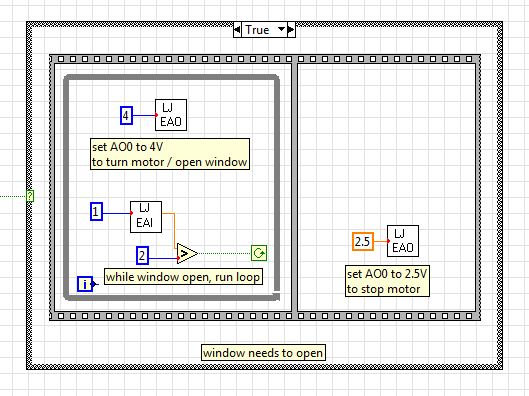
Gradual increase of the output voltage
I use EAnalogOut.vi from LabJack U12 for the U12 4 volts AO0 value. The instant change of output voltage is at the origin of the problems with the engine I use, so I ask: does anyone have an idea how I could program in the current diagram. To move gradually to 4 volts when first executed in the while loop and then little by little to down to 2.5 volts.
Instead of having a value of 4 GB in the analogue output VI, you must have your loop to change the value in small steps. Have a wait function in this loop. Use a shift register to feed into it and increment this registry to offset by small steps. Between the timer of the waiting and the number of steps and the size of the markets, you set will determine how long it takes to ramp to 4 volts. And of course more stages with smaller increments will be a smooth ramp.
-
How the output voltage is coded on 16 bits DAQmx devices?
In our laboratory, we have two devices DAQmx, the NOR-PCIe-6363 and the NOR-PCI-6733. Both have 16-bit for bipolar analog output precision. I understand that the small voltage difference that can be made is 2 * Vref/2 ^ 16, where Vref is the reference AO voltage (10 Volts or externally provided for 6733, 10 or 5 Volts or externally supplied for the 6363).
I wanted to know how the output voltage is coded. DAQmx functions take 64 bit floats as input, and at some point, they must have their reduced accuracy. How is this done rounding, is a floating point around the nearest possible tension, or is always rounded down or always rounded upward?
What is all the possible output voltages? Some diagrams in NOR-DAQmx help/measurement Fundamentals, signals, Analog, sampling considerations seem like they could involve the maximum voltage + Vref is not achievable, so I think that is all of the possible tensions - Vref + 2 * Vref * n/2 ^ 16, with n ranging from 0 to 2 ^ 16-1 included. This includes - Vref and does not zero but + Vref.
Could I get confirmation on this point, or be corrected if it is wrong?
Hi Chris,
The scale of writing DAQmx version performs double floating precision scaling and then he made a turn, the closest to convert the resulting code of the DAC to double int16_t (or uint16_t for unipolar devices). Floating point scale includes the custom scale AO if you have configured one, the conversion of volts or AMPS to the codes of the DAC and for some devices, the calibration scale.
You can check the coefficients of scaling using the AO. Property of DevScalingCoeff. It takes V / A-> CAD codes and scaling into account calibration, but not the scales to customized AO.
The PCIe-6363 X series devices preset scaling in software. The internal reference of the AO is slightly higher than 10V, to correct the errors of gain and offset does not limit the output range. It also means that you are not limited to 9.9997 V on this device when you are using an internal reference.
The PCI-6733 uses calibration DAC instead of software scaling. RAW - 32768 means - 10 V, 0 corresponds to 0 V, 32768 is impossible because of two of the 16 bits of the add-in and 32767 translates 9.9997 V. When you continue 10 V to write DAQmx with this device, DAQmx he forced into 9.9997 V.
Note that for these two devices, the absolute accuracy full scale includes over 305 uV of error. Look at the tables of absolute precision AO in the specs of the device for the full story.
Brad
-
SA520W VPN from Site to Site with several VLANs
Hello
I have a customer here with several VLANS in their places who wants to set up a VPN from Site to site between 2 devices SA520W. Unfortunately I can not find a way to set it up. In the VPN policy, I can choose between everything (which is not what I want, I want only traffict between subnets the routed via VPN), IP address unique, a beach (in a subnet) and a subnet itself - but only one. I don't find a way to configure several subnets in the selection of local traffic and remotely. Adding another IKE policy between the 2 sites does not either (which is good normally).
Any ideas? Anything I'm doing wrong?
Thank you for your help.
Best regards
Thomas
I know that if you have an ASA or a router, you can define as VLANS to pass through the tunnel.
Do not have access to a SA520W to test...
A recommendation might be to post the question on the SMB community where they answered questions related to this product, just to check what other people did.
Federico.
Maybe you are looking for
-
KB976325 crashes IE8 on XP and Vista with a "memory bomb"
After you install KB976325, we see a lot of our web application to customers complaining about their IE8 on Vista and XP exploding > 1 GB, then Windows termination and retrieve the process. Uninstallation of the update solve the problem. Someone else
-
title Windows mail header does not print
Hello When I print all messages from windows mail, it only prints the message body, not his head like, sent to, subject, etc. Kindly give an adequate response thanx
-
videos flash/sound flickering / also insert emails from line (hot flashes disappears)
Help! HP Pavilion DV6-2150US entertainment / windows 7 64-bit Home. Can only see u, all tube videos from other webs (nascar etc) flash/flickering or black screen only hear the sound. Downloaded latest flash player, did nothing. Around the same time,
-
What is the microsoft visual c++ 2008 redistributable - x 86 9.0.30411 in my programs
What is the microsoft visual c++ 2008 redistributable - x 86 9.0.30411 in my programs
-
using a desktop (enter into the computer) instead of the camera microphone microphone
using a desk mic /mixer (going into computer) instead of the camera microphone... Why it will work on windows movie maker, but not the player that is downloaded with the lifecam... I missed something? It should be possible for audio professionals who