VPN and Annyconnect on the same port
You can configure asa firewall to allow the anyconnect VPN and then allow the traffic of users annyconnect cross tunnel vpn on the firewall even on remote site? Users on the local network can connect to a remote site via vpn tunnel but not anyconnect users.
Thank you
Of course, it is a common requirement. You just need to make sure to include the address pool of the AnyConnect users in your access list mentioned by the cryptomap used in the tunnel of site.
Tags: Cisco Security
Similar Questions
-
Questions about serial port read and write at the same time
Hi I create a user interface for the communication serial port, where there are essentially 2 front panels, where the user enters commands one and the other where the prints of UART is delivered. I thought initially using a state machine but the reading and writing may be independent sometimes and so I can't rely on States. I searched a bit on the forum and he left me even more confused. Help, please.
(1) in a thread that sessions visa duplicated has been used for writing and reading at the same time, is it recommendable? How will this affect performance?
(2) essentially when the vi is reading data are it must constantly view as well, however, someone said that it takes too much memory to use shift registers, so how do I go about this? If using a State in queue after the loop of reading it affects the playback loop and be sequential?
In addition anyway is to move the cursor to the latest data from the indicator
(3) for the control of the user input, assumes that the user has entered an order in the control and press ENTER, then writing visa is launched, but if it comes in another string and press enter then write must be called again... is - it possible? will detect the previous commands in the control of compensation?
(4) according to my understand the expectation for the event do not monopolize resources and writing can go in parallel, am I right?
Thank you. I have attached a very basic vi which took me to the point, but I want to make it more robust. Please help especially in the part of the user interface.
su_a,
(1) you can have only one session to a port. Several UART can handle full duplex so performance is not affected. At flow rates of high data and large amounts of data, buffering and latencies of BONE can become a problem.
(2) who told you that shift registers using too much memory? Shift registers are usually the best way to transfer data from one iteration to another. String concatenation inside a loop (registry to offset or not) causes the chain to develop and may require re-allocation of memory. Your VI never clears the string so its cold length become very large.
Generally, you do not have an active cursor on an indicator. If you want to always display the most recently received characters and turn on the vertical scroll bar use a property node to keep scrolls to the bottom. This can be annoying for users if they attempt to manually move the scroll bar and find that the program continues to move it back automatically.
(3) if the user has changed the value in the chain of command, when he hits enter the modified value event fires. Simply strike brace does not change the value and does not trigger the event. Not control need to be erased, but the value that he has to change. If you want to send the same command again, have a button send a command may be a better choice.
(4) write is a case of the event. It is not in parallel with anything. The structure of the event do not monopolize resources. The other loop will run while it waits.
The event loop will not stop when you press the STOP button. Probably it wll take two command: change events of value after JUDGMENT before any loop stops. Replace the Timeout event (which never expires) with a STOP: value change event and a real wire of this judgment to the Terminal endpoint. Remove the local variable. Make mechanical locking when released.
Lynn
-
Prevention and management of concurrent access to the same port VISA
Hello
I currently have a VI with three parallel loop: a loop for the UI with a structure of the event; a loop for the collection of data; and a loop for data tracing.
The loop of data written to the serial port to put the camera to send a probe reading update. The device sends the sensor updated playback and loop bed devices response data collection.
I have a situation where the user interface loop must also 1. write to the same device (via the same port), 2. read the answer, then 3. write using the response data and user input. My problem is that the user interface loop is reading the response of devices in the loop of data collection rather than the response to the user interface loop.
So the problem looks like:
loop data collection: how hot is?
device: 30 degrees Celsius
loop data collection: how hot is?
device: 30 degrees Celsius
loop data collection: how hot is?
loop UI: what color is the sky?
device: 30 degrees Celsius
user interface loop: Ok! the color of the sky is 30 degrees Celsius.
device: Blue
I'm tempted to look for a solution where the user interface loop interrupts somehow the other two loops while it is writing and reading on VISA port, but I doubt that it is the appropriate solution. My code is big enough, but I can try to view if necessary. I remember seeing messages from people with similar problems, but it seems impossible to find today. Thanks in advance for the help!
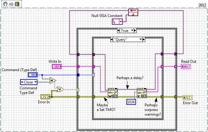
Famous engine Action Nugget of Ben is always a good read. http://forums.NI.com/T5/LabVIEW/Community-Nugget-4-08-2007-action-engines/m-p/503801
Now that you've been through that we will develop a specific EI style that I call a Module on resources. A RM exposes only the functions required by a given application to using an external resource while protecting sections of code of "criticism". In your example even if the VISA operations block several appellants to write simultaineously, you did not protect the operation "Request" critical so readings were responses to the caller of evil. The 'query' is essential and must block access to other operations until the query is complete.
Look at this "Very basic" RM implementation that does not protect the critical query operation:
-
Switch issues. Help, please.
How is it that a computer which works very well with a direct Ethernet connection won't work with a switch, however any other computer using the same port, cable, ect, and so on, can? We already checked the firewall as a question, that it was not, and now, we are puzzled.Well, I know that the issue is long-term... believe me, it's a long, but as they say, the devil is in the details. Anywho, the question is, my grandfather has a HP laptop, which for two years has been able to run through a Linksys switch to his router and connect its printers to his laptop. About two months ago it suddenly doesn't work like that. Now, it works fine if it plugs directly into the router/Ethernet. My uncle suggested that the switch was bad, but after testing the same port, cable and all, the switch worked well for him. ' GRAMPS really needs this answered, but someone else, it is called can not understand and now I, in turn, ask you all for what you can offer. Here are the ideas that we have already discredited.
-Switch bad: as above, is that this particular laptop, even under identical conditions, the works of my uncle very well.
-Bad NIC: debunked through the fact we connected to the computer directly to the router and it worked fine.
-Bad configuration of the firewall: we have disabled the firewall (please do not notice, he wasn't the smartest idea, we already know) and even if she recorded the switch exists, the internet is always triggered when you are connected with the switch.Thanks in advance for any assistance that you can provide and Merry Christmas to you all.
It would be useful to consult the results of the ipconfig/all command both when it is connected to the switch and when it is connected directly to the router. In addition, what is the model of the switch?
To save the manual copy and the new hits of the ipconfig/all command output-
First connect through switch.
Open a command prompt window (start > run > cmd > OK)
Type the following lines in the black command prompt window and press ENTER after each lineecho "Connected via the button" > "% UserProfile%\Desktop\ipinfo.txt".
ipconfig/all > "% UserProfile%\Desktop\ipinfo.txt".Now connect directly to the router, type the following lines in the command prompt window and press ENTER after each line
echo "Connected to the router" > "% UserProfile%\Desktop\ipinfo.txt".
ipconfig/all > "% UserProfile%\Desktop\ipinfo.txt".
Notepad '% UserProfile%\Desktop\ipinfo.txt '.
outputCopy the contents of the Notepad window in your response (if you use the laptop when it is connected directly to the router) or close the Notepad window, and then copy ipinfo.txt of the laptop to the Gramps in a USB FlashDrive you can connect to any computer allows you to answer.
You can delete ipinfo.txt on the desktop when you are finished.
-
RDP Web Interface and connection broker proxies on the same port on 8 MR1
Hello
By reading the whats new document for version 8 MR1, I saw this:
vWorkspace Secure Gateway role Consolidation
All roles in Secure Gateway (RDP encryption, encryption of Internet access and Connection Broker encryption) can now be combined on the same server using the same IP address, port number and certificate server.
.. which made me think that I might have RDP, web and broker any proxy if a gateway using port 443. This would be useful.
However, in the secure gateway proxy configuration tool it has always down:
NOTE: Either the Web Interface can be configured to the same address and the port that RDP proxy proxy or Broker for proxy connections.
Am I misunderstand the information contained in the new document what, or if the text on the gateway configuration tool has not been updated? I share all of the 3 proxies on the same port?
Scott.
Scott, my apologies for the confusion. The text in the dialog box should be removed when the new feature has been added. It was an oversight that has not taken until after the product has been released. We intend to publish a fix that removes the misleading text when we release our next server important side fix.
Marc
-
USBOTG and Charge at the same time on Stream 8
To keep this thread as productive as possible and efficient for those who find it useful to:
Unless you have under your eyes
1. a schematic representation of the 8 Stream USB port (USB port and battery electric circuit etc.)
2 source code for the firmware BIOS and kernel that controls the material
Please DO NOT respond or say "is not possible". In view of the above is true, you do not have enough information to say '' not possible. ''
If no one replys with a solution, what he calls not possible by default.
Also please do not answer to say ' I don't know how "or" but I know how to do anything else that ' is also not that useful.
An update of the BIOS or other software update may be required by HP, Microsoft or both to offer this feature really intuitive and quite possible.
And I hope that this thread can be an effort consolidated by all who have the 8 flow to make the necessary changes. The majority of the other tablet PCs are capable of it. It seems that only the 8 Stream and a few others have trouble with her.
~~~~
I want the ability to use a simple, inexpensive cable and perhaps standard (with electronic active minimum inside) which allows me to host and to use one or more USB devices on the Stream via its USB port B microphone 8 while this cable can also be connected to a charger standard and charge 8 flow simultaneously. This means that the cable has a minimum of three connectors. One of the possible configurations are as follows (apart from the normal charging cable):
1 cable Micro USB B Male - connect to the stream 8
2 USB male A - connect to the AC charger (IE one that came with the 8 Stream)
3. USB A female - one or several connectors to plug into the key of USB data, keyboard, mouse or even a hub.
Connector # 2. above shall provide a power supply to recharge the 8 Stream via conn. #1 and the power supply for external USB devices via conn. #3 so that they are in use - all at the same time.
A and if the same cable can act as a normal OTG no charger for when no external power supply is available. This may necessitate a switch or an electrontics active inside.
The last part of this goal is unimportant for various reasons. I wish that HP, the manufacturer of 8 flow, to State in writing good mode necessary to do this, so that other manufacturers or even-it yourself can make maximum use of their tablet HP equipment.
~~~~
The neat thing it will alow a person to do with their tablet, it is to work at home using the Tablet as a desktop PC by connecting a keyboard, mouse, perhaps external screen (with USB to the display adapter) and knit for a long time without time limit prescribed by the battery life because the charger provides energy to all involved.
If there is only a single connector on the cable #3, then an additional node of coarse had to provide support for these multiple USB devices at the same time. However, it would be better if there were several #3 connectors integrated in the cable itself. This would be better as a suitable USB hub also requires its own power. That an adapter is necessary if the whole thing were integrated into one.
~~~~
I really want answers from anyone who has already accomplished USB OTG delivered with simultaneous load with flow 8. (independent of any published 'proper' way is also welcome)
Today's date is 2015-01-16. If in 2015-02-16 (one month), nobody has posted a solution and then starts to bug HP and Microsoft on it's us?
~~~~
Technical training:
I understand the possibility the tablet software and firmware must take a decision on the manner in which power flows on the power port USB microphone B pins.
I know that with a proper design of the electronic circuit carring these signals of power inside the Tablet could be sensitive to what is connected and without risk to decide for himself what to do without needing to control software. For example by testing/detecting periodically differential voltage or current management to see what sides of the connector can supply.
But this is only one of the many "could bes".
In addition, this can be no standard regarding the standard USB. What seems to be actually the case with a lot of cables OTG + fresh, is that physical clues embedded in the cable or charger are used to signal to the Tablet what the situation is. Then the signal of software/firmware of the Tablet, interprets what the situation is intelligently and responds by flipping the bits of correct hardware control to activate, or deactivate the power flow in the port and also control its direction in or out.
I'm not familiar with the standard USB. Maybe I could do more research, if I believed that HP followed with 8 Stream or even the standard covered this situation explicitly.
But to a certain extent, it seems I'll have to invent something that should be intuitively just like it does with other tablets. Isn't it? Maybe I'm overthinking, but I can't find any USB OTG + cables load that specify compatibility with 8 HP flow.
In any case, I was familiar with both methods other use of tablets to send the highest mentioned signal to the hardware/firmware/software of the tablet to the idea that it's time to load / time of OTG or both.
The first method is a 0 Ohm to 200 ohms short between pin USB A 2 and 3. This is the bidirectional data differential lines D - and D + respectively. In data mode, all the data passes back and forth on those lines. When you load with a cable, it's the charger module that puts this short, not on the cable. I measured the short on three different Chargers. It is 0 Ohms on two of them, one of those who are the charger that came with the 8 HP flow. The others 0 ohms was generic. The third was for an apple iPad and it measured on 53KOhms. It's probably not the resistance ohms 0-200, but probably it is impedance termination indicating that there is some intelligent serial port communication in the charger itself. Leave it to Apple to be different.
This method is somewhat questionable, as this signaling mode would prevent OTG + fee because it seems unlikely that you will be able to OTG when the data lines are shorted each and overloaded with such low impedance. I could be wrong on this subject...
The other method I have seen suggested to work with some tablets and phones other than the 8 stream is too short the USB microphone B pin 5 to Terminal 4 with 0 Ohms to 100 000 Ohms.
USB B has 5 pins. USB has only 4. The extra pin on B moves the GND pin 4 pin 5 pin to and makes pin 4 PIN ID.
If this signal applies to a drop in the ID pin (4) or in some cases, I saw that she proposed, he runs down with 0 Ohms.
Dead shorting things always makes me nervous. If ID is a simple normally high impedance high input, resistance could be used to make voltage well below the low or zero threshold while also preventing the risk of damage when cheat on him with a device that you do not have the diagram for.
Yet, 100K is a bit high for a 'pull down' in most of the situations that I'm used to. Even a 10K would be uncertain. A 1 K or 2 K seems reliable enough, but then things are weaker and in know more nowadays low... All but a dead short but if possible.
So, it seems possible that the device might be able to "indicate" by the specific value of the resistance, which can be found here. In other words the resistance is not a pull down but in fact a signature analog ID, in which case the exact value will be crucial. So if this is the case, a guess is not going to work.
Obviously in such a system as described above, a chip inside the Stream 8 should be responsible to support this information. I hope the 8 Stream has such a chip.
Probably a register inside this chip would be at all times what the State of the pin ID is a binary number. All that is needed is for the BIOS to the chip and the registry in it and read this number via the bus to determine what happens to the port. Finally, he would use that signals of info to send the order of material to the electrontics of power set the appropriate direction to take etc. (and change the State of the icon on the screen of the rude)
I don't know if the PIN ID method described is a standard USB or not either.
Eventually, there may be a third way. But I do not suspect that it would be possible with a non-active external device. In any case too complicated for the novice DIY for sure.
The device would need to act is a kind of extension of bus. As an active hub. But she would use the negotiation of data USB serial lines and in addition to reproduce one or more additional USB ports, intelligently inform the tablet to get with the program which is "now we're going to otg and recharge at the same time."
This requires a smart external device with a processor Inside, no doubt.
It seems to me that many other tablets have been able achieve avecjoint here the need for a smart external device and thus the flow must also be able to do.
There is a device that claims to be able to work with the HP Jet 7 and 8 and provides same ethernet and USB and big DVI ports so loads the data stream. But its expensive because it is active. Se here:
It's called a "Docking Station".
A reference to a product that does exactly what I want (possibly without active electronic components) is here:
It's by Kirin and it is a device of type squid with four USB ports. Precisely, which is my goal. But read in the comments stream 7 user indicated that he would not be OTG and load, not really clear if it worked as a hub USB OTG or not. Another evaluator stated that she would not support even a single USB device much less fees of 8 Stream. This device has a switch.
I forgot to mention that some 'hackers' have claimed success with other tablets to deceive their devices by using a multi-step process to plug things in. Usually in general they would get connected Tablet and load first, then they would return a switch or something remove some resistance or the signal was introduced by the first position of the switch. For some reason any Tablet would continue to require. Then the data lines would be free and they would plug in a usb key and it mounts correctly even if the tablet was always in charge.
It's like the power circuit has a lock which does not allow it to return to the mode "power flow" as long as he still feels the power flows inward regardless of what software it is telling. Full proposal here.
These tips seem dubious to me. Changes in the BIOS could change the way it works. Also you can not be sure what actually happens if you do not have a schematic representation. You could damage your tablet. Many people will support icon in the operating system whether the Tablet is in charge. But I'm sort of a low-risk guy and my policy is generally indicators of intereperet not to have meaning at all once a device is functioning in a non-standard setting. Especially when it's something that I did not built and could not fix if I FRY.
Hypothetical reasoning: tell me what data sensory discs really the State of the charging light screen? This reflect the bit of hardware control programs actually feeding management and status on the port? Or does it measure the direction of the flow of power, said in the section of the circuit battery monitoring? Point - none of us have a schema because it's owner. To really be sure according to the smart electronic hardware, the port must be mode flow under advisement "of power. If it's in a "power flow out" mode and power will be delivered externally as well you wind upward with both power supplies the same power at the wheel nets. In this case, the two opposing regulators attempting both to drive 5 V can have slightly different voltage calibrations. That could lead to fighting between them, with more than 100% of their capacity. For example if you try to regulate 4.95 real V and the other and other attempts to regulate 5.05 V. Current then flows to the tune of 100 mV / a few milliohms in the cables linking the two. This may be several amperes. (many) In other words, like I said: you want the tablet to know that power is coming in don't go out and automatically hitting the internal switches needed for that to happen. Probably the icon should indicate this with precision, but in some wacky situation, he could not. There may be a chance that the icon could indicate the load and still be burning or focusing on some circuits of the tablet or the charger.
Another thing, I could see that happening is if you play with these reported resistance types enough you might find a resistance value that winds up place the device in an intermittent condition. In other words it keeps flipping back and forth quickly between OTG and fresh. It can give the illusion that it works. You can have marginal communication with your USB devices and battery could even load. But will still be a lot of stress on the power circuit.
It is difficult for me to risk a Tablet perfectly well if I don't know exactly what I'm doing.
If a brave individual makes their own experimentation and verifies that it charges and OTGs and you tell the rest of us, you're a hero.
Maybe one of you has a good knowledge on the USB standard to have more confidence in such an experience... like what the ID pin 4 REALLY supposed to work for example?
That's what I know so far. If you think you can help, thanks in advance, or if this helped you, then your quite welcome.
It works
Evidence
http://targusblog.com/2014/11/25/how-to-turn-a-99-Tablet-into-a-workstation/
But it's 4 x the price in Europe
Have fun
-
Lenovo L450 Dock Pro video output DVI and DP at the same time
Hello
I have L450 NB and Pro Dock station.
I have question. Can I connect and use two monitors (1 - DVI, 2 - displayport)?
In this link (https://support.lenovo.com/cz/cs/documents/pd029622) is writable:
3 - any combination
What it means?
If I connect DP and DVI at the same time came out video only on DP.
Is possible to use two screens on the digital output?
Tomas
maniakum wrote:
Is possible to use two screens on the digital output?No, the DisplayPort and DVI Pro docking station port can be used at the same time. So, you need the Dock Ultra.
-
The use of DAQmxWriteDigitalScalarU32 for write channels share the same ports?
Hello
I have a USB-6509 and NOR-DAQmx installed 15.5.1. Using the ANSI c api.
Is it possible to create several independent channels that use different lines of the same port?
DAQmxCreateTask("",&th1)
DAQmxCreateDOChan(th1,"Dev1/line0:4","",DAQmx_Val_ChanForAllLines)
DAQmxStartTask (th1)
DAQmxCreateTask("",&th2)
DAQmxCreateDOChan(th2,"Dev1/line5:9","",DAQmx_Val_ChanForAllLines)
DAQmxStartTask (th2)
....
and repeat for the following strings:
Dev1 / line0:4
Dev1 / line5:9
Dev1 / line10:14
Dev1 / line15:19
Dev1 / line24:28
Dev1 / line29:33So I can use DAQmxWriteDigitalScalarU32 to write to each task independently?
for example:
DAQmxWriteDigitalScalarU32 (th1, 1, 10, 0 x 1, NULL)
DAQmxWriteDigitalScalarU32 (th2, 1, 10, 0 x 2, NULL)
DAQmxWriteDigitalScalarU32 (th3, 1, 10, 0 x 3, NULL)
...
DAQmxWriteDigitalScalarU32 (th6, 1, 10, 0 x 6, NULL)
These tasks will interfere with each other because they use the same port, but are assigned different lines?
If this isn't the case, I bits to the data, if the task/channel does not start at the Px.0 line?
Thank you!
Yes, as long as you use the same line on different channels, they must not interfere with each other for this reason, you can create a channel by line if you wish
The reference to using the DAQmxWriteDigitalScalarU32 function:
"A sample of the integer unsigned 32-bit unique, wrote to a task that contains a single digital output channel. "Use this format for devices with up to 32 lines per port.http://zone.NI.com/reference/en-XX/help/370471AC-01/daqmxcfunc/daqmxwritedigitalscalaru32/
So yes, the DAQmxWriteDigitalScalarU32 can write on each task independently
-
Several Applications using UDP Multicast Open (read only) on the same port
Hi all
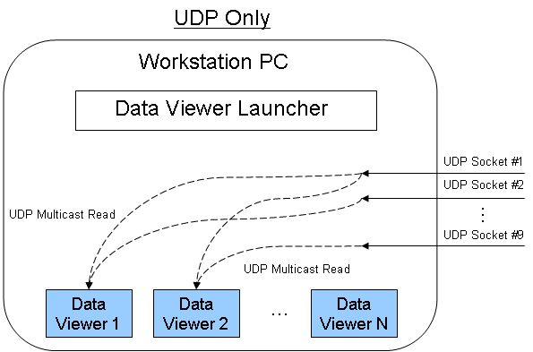
Currently, I am trying to build a system that has the following architecture:
RF Server = "1-9 A/D '-> «UDP Multicast (write-only) 1-9"»
Workstation operator = "QTY (N) Data Display Apps all need independently to access one of the 9 UDP multicasts at a time.
Essentially, I have 9 items of antenna that all digitized and distributed via UDP separate multicast address and port. On the receive side I need to be able to have the N number of data display applications where everyone can select the antenna element he wants to get data from. My current goal for N is 7 and the worst case for the data rate is 3.75 MSps IQ rates on each display.
My question is whether or not it is possible to have several "UDP Multicast Open (read only)" on the same port but one by application Data Display? Also, are there limitations with this.
On my local machine I tried a bit with the example 'UDP Multicast Sender.vi' and "UDP Multicast Reciever.vi". I created a "UDP Multicast Reciever2.vi" as another application that listens on the same port/Multicast address as the original receiver. No errors are thrown when you run the receivers and both receivers get the data string sent by the sender at the same time. Can I send data/a. 'PC'-> 'Router Ethernet'-> 'PC with receiver UDP N' reliable evidence? If so, that's fine, because it would be relatively easy to implement. BTW, I do not fear with occasional loss of data what is happening with UDP.
If this does not work, I am also curious to know which deals with data deduplication. For example, two applications by subscribing to the same Multicast address and port does the router send two copies (which increases network traffic)? Or, the Windows operating system get a single UDP packet to the port and replicate in two independent applications?
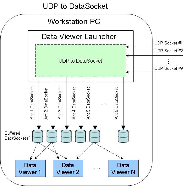
Below (or attached) are the two methods I thought. If multiple readers of UDP does not work so I thought I'd do a DataSocket "Data Distribution layer" between the incoming UDP sockets and display data on the workstation applications. This would add a bit of memory/processor to the PC workstation, but I know the DataSocket server of NOR can handle a sender unique multiple receiver architecture.
Thank you
Tim S.
Hi Tim,.
The number of concurrent applications, get data on the same port UDP will probably be a limitation of the OS as well. If I had to guess, I would say that 7 of the applications should work correctly. In fact, the memory/CPU bottlenecks are probably the limit on how many simultaneous readers we have, especially since the capablities of PC hardware differ from one computer to the other. I doubt that the OS has a strict limit.
-
LabVIEW 6.1 and 2012 at the same computer problem
Hello world.
I've been using Labview 6.1 for a while and it worked fine for me.
I recently installed Labview 2012 on the same computer and looks like the serial port of functions do not work properly. Whenever I try to open an example of VISA communication, labview freezes.
I guess it's because even though I can install two versions of labview in the same computer, the drivers can be installed once correct?
But I thought that labview 6.1 and 2012 may share the same VISA driver.
Is there a way I can resolve this problem with versions of labview works correctly?
Thanks in advanc.
The LabVIEW and VISA compatibility chart is here. As you can see, there is no version of NI-VISA which is compatible with the two 2012 and your old 6.1. Indeed, the graphic poster not only any version of older than 7.1.1 LabvIEW.
-
WebVPN and anyconnect on the same interface
Hello!!
We have ASA 5520 firewall running with code.9.1 (2). We already have webvpn running on the firewall and has active users to use it. Now, the client came with a new requirement to configure firewalls on the same anyconnect. We have installed VPN more premium license.
(1) is it possible to enable webvpn and anyconnect on the same interface. If Yes, what are the aspects we must consider to allow them both on the same interface?
(2) how much webvpn and anyconnect vpn licenses should I do with my premium lincense?
Please help on this.
shver attached for reference.
Best regards
Sri
Your peers licenses AnyConnect Premium gives you the right to access SSL VPN without customer and focused on the customer.
Licensing is based on the concurrent users so regardless of the simultaneous dosing will work - as long as the number of connected does not exceed 100.
Your site to site VPN IPsec does not count against this permission, but is rather against "Other peer VPNS" which does not require a separate license and is limited by the capacity of the ASA equipment (750 on your platform).
-
HOW TO REMOVE 2 PRINTERS INSTALLED UNDER WIN 7 ON THE SAME PORT (LPT1)
HOW TO REMOVE 2 PRINTERS INSTALLED UNDER WIN 7 ON THE SAME PORT (LPT1)
Microsoft answers site provides support in English. The following Uniform Resource Locator (URL) will be low - you receive information appropriate for your set up support. Open the link and get your region from the drop-down list, and then click the arrow to continue.
-
How to get the ASA packets that come in and out on the same interface?
Hi all
How can I configure the ASA5520 routes the packets that come in and out on the same interface? I ve more than 1 network behind the camera of the SAA. It s separated by internal router. They can communicate with each other.
I've seen it's PIX design problem. She applies to the platform of the ASA?
Please advice.
Thank you
Nitass
This golden rule remains immutable. the only exception is the vpn traffic. ASA for example (or pix v7) would act as a hub for traffic between two rays rediect vpn.
regarding your question.
Internet <-->asa <-->1 <-->lan router <-->lan 2
assuming the host to lan 1 to asa as the gateway default, even asa has a static route to the internal router of the point for local network 2, the golden rule will reject this operation.
one solution is to re - configure the dhcp on the LAN 1 scope and make the internal router as the default gateway; and the internal router has the asa as the default gateway.
-
client ipSec VPN and NAT on the router Cisco = FAIL
I have a Cisco 3825 router that I have set up for a Cisco VPN ipSec client. The same router is NAT.
ipSec logs, but can not reach the internal network unless NAT is disabled on the inside interface. But I need both at the same time.
Suggestions?
crypto ISAKMP policy 3
BA 3des
preshared authentication
Group 2
!
ISAKMP crypto client configuration group myclient
key password!
DNS 1.1.1.1
Domain name
pool myVPN
ACL 111
!
!
Crypto ipsec transform-set esp-3des esp-md5-hmac RIGHT
!
Crypto-map dynamic dynmap 10
Set transform-set RIGHT
market arriere-route
!
!
list of card crypto clientmap client VPN - AAA authentication
card crypto clientmap AAA - VPN isakmp authorization list
client configuration address map clientmap crypto answer
10 ipsec-isakmp crypto map clientmap Dynamics dynmap
!interface Loopback0
IP 10.88.0.1 255.255.255.0
!
interface GigabitEthernet0/0
/ / DESC it's external interfaceIP 192.168.168.5 255.255.255.0
NAT outside IP
IP virtual-reassembly
automatic duplex
automatic speed
media type rj45
clientmap card crypto
!
interface GigabitEthernet0/1/ / DESC it comes from inside interface
10.0.1.10 IP address 255.255.255.0
IP nat inside<=================ipSec client="" connects,="" but="" cannot="" reach="" interior="" network="" unless="" this="" is="">
IP virtual-reassembly
the route cache same-interface IP
automatic duplex
automatic speed
media type rj45!
IP local pool myVPN 10.88.0.2 10.88.0.10
p route 0.0.0.0 0.0.0.0 192.168.168.1
IP route 10.0.0.0 255.255.0.0 10.0.1.4
!IP nat inside source list 1 interface GigabitEthernet0/0 overload
!
access-list 1 permit 10.0.0.0 0.0.255.255
access-list 111 allow ip 10.0.0.0 0.0.255.255 10.88.0.0 0.0.0.255
access-list 111 allow ip 10.88.0.0 0.0.0.255 10.0.0.0 0.0.255.255Hello
I think that you need to configure the ACL default PAT so there first statemts 'decline' for traffic that is NOT supposed to be coordinated between the local network and VPN pool
For example, to do this kind of configuration, ACL and NAT
Note access-list 100 NAT0 customer VPN
access-list 100 deny ip 10.0.1.0 0.0.0.255 10.88.0.0 0.0.0.255
Note access-list 100 default PAT for Internet traffic
access-list 100 permit ip 10.0.1.0 0.0.0.255 ay
overload of IP nat inside source list 100 interface GigabitEthernet0/0
EDIT: seem to actually you could have more than 10 networks behind the routerThen you could modify the ACL on this
Note access-list 100 NAT0 customer VPN
access-list 100 deny ip 10.0.1.0 0.0.255.255 10.88.0.0 0.0.0.255
Note access-list 100 default PAT for Internet traffic
access-list 100 permit ip 10.0.1.0 0.0.255.255 ay
Don't forget to mark the answers correct/replys and/or useful answers to rate
-Jouni
-
Opening a database must be in the same port?
I have a problem when opening the database with a different port.
What I do is simple:
1. create the database in a given example port: 62398
2 - I shut down the database
3 - I RE-OPEN the database in another port, for example: 62358
When I create the object:
new ReplicatedEnvironment...
The system shuts down. He will wait in this line of code: new ReplicatedEnvironment
I create a simple method to get a new free port:
public static int getFreePort() {} freePort int = - 1; try {} ServerSocket serverSocket = new ServerSocket (0); freePort = serverSocket.getLocalPort (); serverSocket.close (); } catch (IOException e) {} e.printStackTrace (); } Return to freePort; } The port is available.
The problem is not the free port, because if I use this free port to create a new database, it usually creates.
If I try to open the database with the same port, it will open the dabase correctly.
I already tried to delete the *. je.info when re-openining the database with different port, but it does not work.
I HA interface requires that host names and ports for the nodes must be changed explicitly using an administrative order. Start the node with a different port, or on a different host, is not enough.
HA I stores information about host names and ports of members of the Group of replication constantly under the mechanism it uses to identify a quorum and needs to be notified of the changes correctly to avoid the risk to elect multiple (and competing) masters.
The following reference from of the manual I HA provides general information on the configuration of the nodes, with a reference to make updates at the bottom:
http://docs.Oracle.com/CD/E17277_02/HTML/ReplicationGuide/nodeconfig.html
In particular, you can use the DbGroupAdmin utility to update the host name and the port of an existing node. Please take a look at the documentation and write back if you have other questions about the use of these utilities.
Also note that the *. je.info files are not where the content of the database is stored. These files contain the debugging logging that is for people to look at when they notice problems with the system. The database data is stored in files with names like 00000000.jdb (or many more). But just to delete these files is not a good idea in general, and would have not fixed this particular problem.
-Tim
Maybe you are looking for
-
Crash ID: bp-989a58f4-d90d-4595-8d00-16f6f2130409
Crashes when starting application, Crash ID: bp-989a58f4-d90d-4595-8d00-16f6f2130409
-
Recover contacts from a broken iPhone
Recently, my 5 c overheated and fried. If it lights at all, I get the head start symbol with a bunch of error code and the phone immediately starts to get hot again. All my contacts are there and I can't access it. Is there another way to recover con
-
P850 satellite with Win 8.1 - Hercules rmx dj controller does not
Since installing windows 8.1 on my P850, I could not use my rmx Hercules dj controller. Team support for the State of Hercules is usb 3.0 eXtensible Host Controller entry is recommended to go to the link and follow the instructions to update the driv
-
New MacBook Air cannot pass the "Sign In"
just bought a MacBook Air and can't seem to make it work. It's like that for the last 30 min. I keep waiting or? Thank you
-
Cliq 2.1: Anyone know how to restore contacts from T-Mobile?
I know there is a new application for tmo contacts but how makers? Also when I try from the website it sends garbage to my phone and put it in a file of T-Mobile. Contacts are just numbers. Any ideas?