with pulse width measurement external sample clock
Hi all
I use a NI 6220 (programming with ANSI C) Board and I would like to make a "unique pulse width measurement' by using a signal from the outer door and an external signal source.
The program and the card with the help of the "DAQmxCreateCIPulseWidthChan" command works only partially as expected. Namely, the outer door has worked, but the map uses the internal time of 80 MHz base signal instead of the external source connected to the source by default PIN (PFI, 8).
I tried send an another PIN PFI on the default source pin using the command 'DAQmxConnectTerms', but this did not help either.
Obviously, I'm missing something...
Best, Uli
Hi Uli,
I posted in your thread here.
Best regards
Tags: NI Hardware
Similar Questions
-
NI6602 pulse width measurement: do I have to use an external sample clock?
Hello
In the example .NET 4 "MeasPulseWidthBuf_SmplClk_Cont", it is said in the comments that:
An external sample clock should be used.
Hi mola.
This specific example measures of sample-clocked pulse width. This type of measure is supported only on new hardware such as the X series cards and will not run on the 6602.
Your application that you have linked uses Implicit timing, which means that the signal is using the sample clock. In other words, at the end of each pulse duration which can be measured, the sample is deterministic locked in. So you end up with a table in the buffer of each pulse width which is seen by the meter.
Best regards
-
Measurement error of the County of edge by using the external sample clock
Hello
I'm trying to measure the number of edges (rising) on a square wave at 5 kHz with a generator function on a device of the NI PCIe-6363. I configured a channel of County of front edge of counter at the entrance of the PFI8 device. I use an external sample clock that is provided by the output of the meter of a NI USB-6211 housing channel. If I acquire for 10secs then ideally I would expect to see a total of 50000 edges measured on the meter inlet channel. However, my reading is anywhere between 49900 and 50000.
When I use the internal clock of time base to measure the edges, the measure is accurate and almost always exactly 50000. I understand that when you use the external sample clock, the precision of the measurements is subject to noise level of the clock signal. However, I checked the clock signal is stable and not very noisy. Any reason why there is an error of measurement and how tolerance should I expect when using an external sample clock compared to when you use the internal time base clock?
Also, what is best clock Frequency (with respect to the frequency of the input signal) when using an external clock?
Thank you
Noblet
Hi all
Thanks for all your sugggestions. I was using an input signal with a function generator which had a range of 8V. It turns out that the reduction of the amplitude to 5V solves the problem. I was able to get accurate numbers with the 6211 external clock.
Thank you
Noblet
-
How can I use two counters simultaneously to pulse width measurment
Hello, everyone!
I'm new to Labview. I currently have some cDAQ9171 and width measurment with 9401 impulses. My understanding is that the 9401 was 4 meters, which means that I can use these meter separately. However I have the following problem.
1. I use ctr 0 and ctr 1 (PFI 1 and PFI5) to measure two different impulses. However, it seems that there is an interference between two counters. How can I make two counters working simultaneously and separately?
2. I first try a pulse width measurment counter in Labview signalExpress. My pulse width is about 0.4ms. However, I can't get the right result, if I choose the starting edge is on the rise (the results always around 20ns. Only if I revise my pulse and pick the starting edge is down, I can get reliable results.
I'm confused about these issues for about 3 weeks... Is there someone can help what can I do with that?
I have attached a simple vi...
Thank you very much!
-
External sample clock change takes a lot of time on the SMU-5186
Hello
I use the external Lv - niScope EX Clocking.vi example to define SMU-5186 using an external sample clock. However, it takes a long time, 5-6 minutes, before I can get the first block of data acquisition.
Then I run the example 'niScope EX Acquisition.vi Configured' to switch to dashboard clock. There are also 5 to 6 minutes on the first acquisition.
I think maybe the SMU-5186 made some calibration when I change the source of the clock.
Anyway is to ignore the calibration? Or make it faster?
Thank you very much
Yiming
Yiming,
Delays in acquisition are caused by calibration routines that must be performed on the engine to sample (ADC) every time that changes sampling rate. This ensures our justified precision specifications.
I don't know if you've noticed also calibration of Power-Up, which will take 5-10 minutes to complete when the unit is turned on. This is mentioned in our specifications at page 18:
http://www.NI.com/PDF/manuals/373257b.PDF#page=18
I hope this helps.
Nathan
-
An external sample clock between sharing arrangements
I need to acquire samples of 2 separated Renault M series (PCI-6254). My master device receives a sample of 8 on PFI0 KHz clock. Is it possible at the root of this clock of the master to the slave via a RTSI cable device?
I looked through the forum and the sample programs, but have only seen examples in which the master clock on board the aircraft happened to the slave.
It is possibe to synchornize device slave the master clock to external sampling of the device?
Thank you
ANT1
ANT1,
Fortunately, most of the time something that can be done in DAQmx in LabVIEW can be done in ANSI C using the appropriate function calls. I have listed the following steps of the program example LabVIEW and retouched to remove anything that it is not suitable for the DAQmx configuration. I'm sure it should work for you.
Steps to follow:
1 create a channel of analog input voltage for the master and the slave.
2 set the synchronization parameters. For the master, select the source of the external sample clock. Set the source AI/SampleClock of the master for the slave device. (Note: sample of the master clock is automatically routed through the cable RTSI.)
3. for the slave, set the Source of the trigger to the AI/StartTrigger of the master device. This will ensure that both devices start sampling at the same time. (Note: the trigger is automatically redirected via the RTSI cable.)
4. call the start task to start the acquisition. (Note: start slave task before the master task.)
6. read all waveform data.
7. call the clear task to stop the acquisition and clear the task.So, essentially, the value of the task of the slave to the top in the same way as you would for the synchronization of clocks on board, but configure the task to master as you would for an external clock. This will automatically share the external clock and trigger on the line of the RTSI.
-
Synchronization of analog and digital output with the external sample clock
Hello
First of all sorry for my English, I will try to explain what I want to do.
I want my PCIe-6321 to send two custom signals (modification sawtooths) on a mirror controller. I would also like to generate output with my card at the beginning of each tooth of saw. Everything must be synchronized with an external k-clock signal of 100 kHz. The idea is that whenever the PCI receives a trigger to external clock, it sends two analog output voltages and when he received 1024 clock ticks it will also send a pic of triggering TTL. What I do is first prepare the map and after that in a loop sending and modifing the output values of the two signals and at the same time send a digital signal Boolean in each arch, so when's done it 1024 iterations of the loop I send an event to the digital port. Attached you can see.
The problem is that I don't know how to synchronize both. Can I use the sample clock just to the analog output? I can use sample for the two outputs clock, or do I need to use the output of the meter? If don't know how to use it here.
If I do nothing else bad/wrong, I would be grateful for feedback.
Thanks in advance,
PabloI don't know how but I find the solution. I'm generating more than a positive value (as I was triggered maybe very fast the oscilloscope has been absent there). If I put the sample clock of digital output to use the sampling/ao/Dev1 clock that it doesn't, but if I put to use the same source as the OD (terminal where my external clock is connected), but the trigger to start the DO to be Dev1/ao/StartTrigger this works. I don't really know why, but it does.
Thank you for your patience and your help. I put here the final code.
-
sampling frequency of DAQ assistant for pulse width measurment
Hi all. I want to measure the pulse width of a digital signal of about 1 kHz, via digital DAQ vi assistand pulse width. I need to measure the pulse width approximately 100 Hz.
I put 1 sample on request and in one of the other method of as implicit synchronization for continuous measures that I met at the error. He doesn't let me frustrating that I could not measure a measurand jut at 100 hz.
I use Daqmx and windows 7 sp1 and labview 2012.
Thank you
OK I have the solution, it's better to see the example and do not use daq assistand and use the primary functions.
Counter-read Pulseand width and frequency .vi (continuous)
-
single pulse width measurement
Hello
I'm trying to measure the duration of a single pulse using ctr0 on an SMU-6361.
The signal in the attachment Capture7.jpg, goes PFI 9, ctr0 door.
The problem is that the counter see ' s the front up and stops. The pulse width is not given as can be seen in the output (Capture8.jpg).
I get the same results by using Meas_Pulse_Width.vi example.
Is something wrong with my SMU-6361?
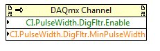
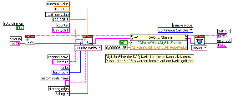
Oh, I think I know what it is.
Change the task "pulse width" (a single pulse of height) instead of "Pulse" (the high and low time of a pulse repetition measures). Change the DAQmx Read to use Ctr > single sample > DBL (instead of pulse). Change the property filter node digital to use the corresponding properties of the "pulse width" (the filter is still necessary):
The task of the pulse was not period initially because you receive a series of noise pulse repetition (and so it was a very low period). With the filter, this time since the noise disappears now and the single pulse did not finish measuring the pulse (which requires a high and some time):
For the record, I agree that it is confusing that there is the "pulse" and "Pulse" measure and they do different things.
Best regards
-
signal level for pulse width measurement
Hello
I am able the pulse width with the meter M6251 (CI pulse width)
I understand that the digital input works on the TTL levels (0, low 8V 2, 4V high).
Can you say exactly in which the level of signal pulse width is measured?
Thank you
Ralf
In fact, the transition from low to high (or vice versa) is located in between 0.8V and 2.2V. It is not specced exactly where it will be (although you'd be able to get a better idea, if you have an analog source, you can slowly increase until you see line status change).
This is why the fast rise time are important to accurately measure the digital signals.
Best regards
-
NI 9401 pulse width measurement.
Hello
I'm not sure that I understand very well the pinout diagram. At the present time, I have a NI9401 in a NI 9172 chassis.
DIO0 and DIO1 are connected at the gates of light. I have an opto switch and I want to measure the pulse width when an object blocks passes through the slot. Can I use one of the other free entry of the for do?
The entries are DIO2, DIO4 and DIO5.
The other IO pins are used as triggers.
See you soon
K
Hi Kamilan,
If you explore in the measurement and Automation (MAX) and find your 9401, you can right click on the device and select "Pin of the device" which pulls up a window that says what features each pin on the device. For example, according to this document, DIO2 is PFI2 to THE CTR0 CTR0 B and FREQ OUT.
To answer your second question, do a right click on your device and create a new task for your 9401. "You should do an acquisition of signals" counter input "pulse width and select CTR 1 on your device. Once you do this, you can configure the parameters of your task and Max it will tell you where you need connect your signal source, which, for me, is DIO5.
I would like to know how it works for you, thank you!
-
Looking for USB DAQ for AO using the external sample clock
Hi all
I'm looking for a cheap solution for the acquisition of data to select the AO using an external digital signal as sample clock, and I just realized that the USB-6001 is not a good candidate. Please someone remind the cheapest USB version for this task? There no need for high sampling rate. Thank you.
Define cheap and low sampling rate. You've already been told on the 6211.
-
PXI-5122 external sample clock
Hi csk,.
I was wondering if you could clarify how
you want to take samples. Am I right in taking 30 000
sets of 150 samples each, or do you mean that you take 150 sets of
30 000 samples each (since 30 000 periods of 60 MHz clock corresponds to)
less than 90% of a 1.8 kHz signal)? In both cases, the current method you
are using only will acquire a single record each time by
the loop, and so you will be limited by how fast you can retrigger in
software.For your application, it looks like you want
need to perform a multi-record acquisition, which will allow you
specify what condition to trigger off of and how many samples of
acquire whenever the trigger occurs. In this way, each 'transition' of the sawtooth wave is considered to be a single record, and you buy several different corresponding records whenever a rising edge trigger occurs. I think you can accomplish
exactly what you need with only a slight modification to the niScope
example of expedition "niScope EX Multi Record go get more available»
Memory.VI"(se trouvant àles Start» Programmes» National Instruments» NI-SCOPE)"
("Examples). With this VI, you can specify that each record you want to
have a record length min to 30 000 samples (or 150 samples, if it
the case) and you want to acquire 150 records (or 30 000 if this)
that is the case). The only big change that you need to do is to
change the trigger VI set up to be a digital dashboard rather trigger
only an analog trigger. With that and a few other changes (i.e.:-)
setting the external clock), you should be able to accomplish what
You need. Please let me know if I have explained well and if my
assumptions are correct. Thanks and good luck! -
Full range of pulse width measurement
Hello
I'm having a problem with the measurement of PW, I need to read an operating cycle within a range of 0% to 100%. The problem I have is the signal does not cross the Middle time enough baseline to measure or the histogram cannot be used because the amplitude is zero. Yes, this is obvious, because there is no pulse, that's basically all true or all false these two extremes, but the pulse measurement vi cannot handle this. Is there another way, I could measure the market factor, so that I can see if there is a hollow (0%) or high (100%) and everything in-between without errors? Even when I measure the PulseWidth in the method of the Ridge, rather than the histogram method, which gives me more time to remain at 0 or 100% before it gives an error, the measure see the signal as duty cycle 50% (still a times obvious because it is neither salvation nor low for any length). So if I could still read 0% or 100% error free, how would I be able to block the two extremes of the never read? My entry is the acquisition of data, so I can't just 'limit' my input to the source signal...
Any suggestions?
Thank you
-Corbin
Hey, Henrik, thanks for the reply,
I didn't really know how to integrage over a period of time in LabView, and I read a wave of digital squares (duty cycle). I found that I needed to omit extreme values such as 0% and 100%, so I couldn't find a way to do this with one under VI. What I found is my solution: I knew that + 12V has to be 100%, and 0 v is expected to be low, so I just used 'Amplitude and level measurements' sub VI read the RMS value, used a table that I recorded correspondence (via MatLab help), and I have more problems with errors due to levels of reference of histogram (do not use histogram now...). My application can read everything from 0% to 100% and he returned my correct data after handling. Success!
He could go about resolving the issue differently, but it works.
-Corbin
-
Problem with DAQmx Schedule VI (sample clock)
Hello to you all,.
I'm new to this forum, please bare with me. I have some experience with LV, but I am relatively new to data acquisition projects. I use LV2009.
I want to make sure that I use the hardware timing (instead of software distribution) in my project so I followed some of the threads here as sugested to use DAQmx Schedule VI. The problem is that no matter how I set the system I get the same error-200300 invalid calendar
type.The project is simple. I encode with 1000 pulses per
Rev and it is mounted on a shaft of a turbine water goes thru. I'm watching the frequency
and so the rotation of the shaft which tells me that the amount of water flows through the turbine. In the end, there will be 2 channels
by every encoder and ~ 3 encoders (turbines) total and calibrated the main meter that will give me constant impulses and all encoders will be compared to this master frequency.I'll use PCI6602 DAQ, but
now, for the development, I use USB6221. Let's say that the
frequency is between 500 Hz and 10 kHz. What I am doing wrong? Or maybe better to ask - what would be the right approach for this project?Thank you
Marty
Hi Marty,
It seems that your question is already answered here, but Jason is correct that the 6221 neither the 6602 support a clock sampling for frequency measurements.
As Jason mentioned, your best bet is also likely set the mode of synchronization for "implied". This means that the frequency value is sampled at the end of each period of your input signal. In addition, a solution that is clocked by the software (On-Demand) might be acceptable.
X Series DAQ devices allow an external sample clock to use for frequency measures (described in the Manual of X series). Frequency of sample-clocked measures are useful in very specific
circumstances, but it does not seem that you need this feature based on what you've described so far.(621 x) bus-powered M series can also be configured to use an external sample as the X series clock but do you not have the same features described in the manual of the X series.
I hope this helps!
-John
Maybe you are looking for
-
Running a Mac w / Snow Leopard Followed all the installation procedures. I have manually setup my router name and password and the info is recorded and accepted. Problem is, when I go out the USB cord, he doesn't speak. USB is plugged, all right,
-
Satellite Pro L40 - how to move from a Vista to XP
Hi all I would like some info on "how a Vista to XP downgrade?I have an original XP SP2. Please help...I tried before, but the sound does not work... help please Apreciate will please and thanks in advance.
-
After launching a video in Windows Media Player, I tried to jump forward or backward using the "line of play or progress line" at the bottom of the display area. The sound will be either go forward or backward, but the image freezes. Most of the time
-
recently some gif files are not open. Get all the white screen (white)
Experience the problem on a few sites. problem started about 1 week ago. newly installed Firfox 4 and conducted an analysis of the registry using the may/may not be a problem. RegCure due to the performance of slow computers. Had done this earlier a
-
HelloAfter upgrading to windows 7 Home premium 64 bit vista family premium 64-bit, I expected to be able to connect my EPSON Stylus D68 printer on my laptop and leave immediately. However, when I tried to do this installation constantly failed. Ther