3 voltage/current measurement channels, crosstalk between channels
Hello
I am running a NOR-USB-6211 is connected to an instrument that runs labview 8.5. What I want to do, it's current 1 and 2 channels of voltage measurement channel. All are separate physical channels. I use an express VI to separate the 3 channels on the box USB-6211 and trying to draw on maps of distinct waveform stacked in a way that it respond independently (as they should be physical separate circuits). I can ALMOST that it works. I can measure the current very well. The problem is with the tensions. If I change the voltage on channel 2, channel 3 meets both equally (eg. increase 5V on channel 2, channel 3 increases of 5V); However if I change the voltage on channel 3, channel 2 does very little (such as increase of 5V on channl 3, ~0.05V increase to channel 3). Not the best result, but better than the reverse. Channel 1 is not affected by changes in voltage, but it affects the Channels 2 and 3 (current increase, increase of tension of channel 2 and 3). I have no idea why this is happening. I saw the same thing when I used only 2 channels (current and voltage). When the current (channel 1) is changed, the (channel 2) voltage changes, but when the voltage, the current does not work. There must be a problem with the program because I get the same behavior when I physically disconnect channel 3 (for example, always responds when I change the voltage of channel 2). It seems like it should be a simple installation and a simple solution, but I can't understand it.
I've included a snapshot of the program. I share the channels so I can selectively save some data in a file. I tried to simply connect the VI express to a graphic, and does not either (tensions influence each other). I also tried to replace the cluster with a table, but that did not work or the other. I tried to simulate the data with sine waves and I can get this to work without problem. I don't know what I can do.
Thanks for your help.
The f
interference of signals of high-level signals at low level is normal with inputs high impedance of a multiplexer.
put a short channel shorted inbetween and measure this also but throw the zero.
Tags: NI Hardware
Similar Questions
-
I use the driver for Tektronix TDS3000 Labview to configure an TDS3034B oscilloscope and I try to measure the gap between the falling edge of a pulse on channel 1 and the edge failling from an impulse on channel 2. It seems that the TDS3034 can measure this in in-house by the use of the measurement on the front panel key, but how do I retreave using your labview driver?
Hi Tori
I am now in place and running, I already had the TDS3034B to measure the delay between the pulse on channel 1 and the pulse on two channels, as well as the pulse width tuned to channel 2. This was done by saving the settings on the scope on a diskette and cutting and sticking them in a modified version of the TDS3000 auto setup vi. I created from a simple VI which allowed me to manually enter orders for tektronix and found that the command "measure: meas1: data? went around.
Thanks for all your support on this issue.
-
Incorrect voltage to a channel with NI9205
Hello everyone
I measure 10 tension of cell with a NI 9205 (differential mode, volt min. = 1, maximum voltage = 3).
Everything works fine, until tensions are higher than 2.7 V. channel 17 (cell number 10), the voltage begins to decrease.
All the other channels (0-7 and 16) works correctly.
For example, when the real tension is 2.72, the measure shows 2.64 (and the value is not very stable). The more the voltage of the cell increases more 2.7 V, the more the measure of this cell voltage begins to decrease.
I also connected the voltage of channel 17 to channel 18, but the problem remains. Both channels show too low voltage (but not exactly the same value).
My sampling rate is 15, my conversion of clock frequency is 200.
In addition, I have two NI9217 in my cDAQ-9172 chassis to measure 8 temperatures.
Everything is measured in a task (10 voltages, temperatures of 2 x 4).
Any ideas how to fix?
Thanks and greetings
Socki
Socki,
with 10 cells in a row you are likely well beyond the sides of the 9205 input voltage. Please note that the 9205 offer channel for floor insulation, but not from track to track. The voltage for each channel must remain in +/-10.4 V of the common. With your stack of the cell you are probably larger than this limit and reduced tension that you see is the result of the entry of the 9205 amplifier starts to saturate.
As a solution, you will probably use a second analog input module and divide your channels in the middle of your stack of the cell.
Kind regards
Jochen Klier
National Instruments
-
scanning voltage and current measurement for Keithley 2400
Dear all
Hello
can someone help me?
Despite days nearlly10 I am option to find any program LabVIEW 2010 for sweeping the voltage and measure current who works with RS-232, I have a end not have nothing exept examples read single and multiple data. I tried to SmartData labview and changed a few prorgram gpib to RS - 232, but I couldn't.
In another attempt to find a good VI "votltage scanning and current measurement" that work with RS-232 in labview 5.1.1. I have converted in 2008, but it takes old driver (ke24xx.dll) and do not work in my labview 2010 and I could ' t find older driver.
My thesis project was halted in those 10 days, and I couldn't do anything for our keithley.
Please helpe...
in the following, I have attached these files:
1.-first, what voltage scan that works with GPIB
2 - Vi that I change the gpib for visa (rs232) port that I don't know why it doesn't work.
3. it is Vi related to the "sweeping and current measurement votltage" that works with the RS-232, but it takes old dirver so I can't use it.
4-slot-VI necessary for the implementation of program 3 (but there is no driver for these subVIs) was attached to the reply message of this post
If any body has this program ("scan votltage and current measurement" running rs - 232) please send to me
Thanks in advance.
None of you attached the screws are the driver OR you spoke. There is no conversion required for this driver.
-
How can I measure the time between each two successive increase edges, using digital input?
Hello
I have tried two measure the time in seconds between each two successive rising edges on a digital input.
So far I managed to detect the rising edge, increment a counter at each rising edge and take the time during which the increase is edge
all I need now is subtract edge currently rising from the previous era of edge rising to calculate (T), which can be 1/frequency and display in real time for the user.
but I do not know how to do this

Can someone help me please!
Woah!

Sorry Apok, but your code becomes much too complicated and salty. I don't think that all records to offset or Boolean conversion/operators are necessary at all.
If you want to measure the time between two keys so it's another (much less complicated) way. It simply records the time when press button in a registry change, then compares the two.
-
How can I use 2530 b and 4065 to measure the resistance between two selected pins?
I want to be able to select 2 corners on a test with 2530 b set-up and measure the resistance between them with a 4065 DMM (PXI all). Ankles in question are each in blocks of 32 different poles, so I can match them in a double configuration 32 x 1 four or 64 x 1 if necessary. I can measure the resistance between several different pine sets as 0 on 33 pine pine, pin 0 at pin 34 pin 0 to 35 pin and pin 1 to 34 pin, pin 1 pin 36, etc.
I understand how to measure resistance between a given pin and Earth using the the 2530 4065/b using the wizard OR-DMM/Switch Express, but it is unclear if I can measure the resistance between the two pins of selected by different user. I am a newbie of labview, used to write things in c#, so it may be something very trivial (I hope).
Any ideas?
Thank you
-Russ
Hey Russ,.
I recommend starting with the following example (located in the Finder the example ('Help' to find examples):)
"" Material input and output"Modular Instruments ' OR-Switch" niSwitch Dmm Switch Handshaking.viBecause you use a scan list, you can simply drag the two connections to the same entry and then the switch will wait for the two to settle before you send a trigger of the DMM... problem solved. For example, to connect the CH1 to Com0 (DMM +) and CH93 to Com4 (DMM), then take a measure, then connect CH38 and CH120 to the DMM, you would use the entry list of scan to the following address:
CH1-> com0 & ch93-> com4; CH38-> com0 & ch120-> com4;
Note You can have as an entry in list of switch module scan. In addition, you can only have a single advanced analysis and a measure full per switch module.
-
measure the distance between 2 impulses (PCI-6221)
Hello
I have a digital signal that sends a pair of impulses (100ns width each) roughly every 100ms and I measure the time between two pulses of a pair (with a resolution of 100 ns).
For the moment, I got a card PCI-6221 to accomplish this task. Unfortunately, I have no solution until now only measures of counter, I found measure time between constant frequency signals, i.e. they cannot measure the distance between 2 single pulses.Any help / ideas / or even telling me that it is impossible to solve this task are appreciated
Are the two pulses on the same line?
If so, you need to just configure a task of the measurement period. If they are on separate lines, you would use a task of "separation of two-edge.
You might be to throw off by the timing of it:
If you do not configure implicit synchronization in your task, will start on the first edge after DAQmx Read is called. Thus, in order to intercept the signal, that you must configure your task, call DAQmx Read and then start your two squares.
If you want the task to control the signal continuously, you must configure name timing. In this case, you will receive a sample on each rising edge of the external signal (assuming that the two impulses on the same line) - If you start the task of counter before starting the production of pulses (which you probably should), then the same samples correspond to the time between pulses, the odd samples would be the time between each series of pulses.
More information on modes of counting on the 6221 lie in the M series user manual.
Best regards
-
Measure the time between the ridges of the periodic input signal
We have built a circuit which is supposed to mimic an Exercycle. We have an IR switch and a spinning wheel, the rccb meets a comparator circuit and the output of the element of comparison, we have running in LabView. We successfully were able to measure the number of rotations of the wheel and the total distance travelled by the wheel, but are struggling to measure speed. We cannot find a way to measure the time between picks in real time, which we could then divide the wheel circumference and calculate the speed in real time. The VI I posted has a square wave simulated rather than the signal we receive on our circuit. Thanks in advance for the help.
Jon and David
I think you're overloading the things trying to get the time between two pulses. Instead, you can use the VI Express your measures and select frequency for her custom. Then, you can multiply the circumference of the wheel of the frequency to get the speed.
I hope this helps.
-Christina
-
Measure the distance between 2 points of glare
Hello
Does anyone know how to measure the distance between 2 points (attached Image) glare. The image shows 10 sets of points of glare. I appreciate if you can guide me to process the image and produce the algorithm to detect the 10 sets of points of glare and measure the distance from each game.
Thank you
Farid
Check if this will do
-
How to read voltage on several channels using the 6255\SCB-68
Hi all
I have been able to get the following code to compile, run and display the data as expected. When you read the tension (CSR) on Dev0/ai65
... Instruments\NI-national DAQ\Examples\DAQmx ANSI C\Analog In\Measure Voltage\Cont Acq - Int Clk\ContAcq - IntClk.c
* I think I'm using CSR, but I have no idea since I don't see an argument to specify
I'm reading two different data points:
1 discovered (CSR) tension on Dev0/ai65
2 show the (differential) voltage difference between Dev0/ai17 and Dev0/ai25
Can someone point me to an example (or a web link) where two different data points are read.
* edit - I am filling this task using C++
Thank you
Chad
This code is a start, and it works
using namespace std;
using namespace std;#define DAQmxErrChk (functionCall) if (DAQmxFailed (error = (functionCall))) goto error; on the other
int main (void)
{<>
< "\t="" starting="" the="" ni="" daqmx="" data="">
<>int loop;
< 3;="">
{
Int32 = 0 error;
TaskHandle taskHandle1 = 0;
TaskHandle taskHandle2 = 0;
Int32 read1.
Int32 Read 2;
float64 data1 [1000];
float64 data2 [1000];
tank errBuff [2048] = {'\0'};Channel settings and the schedule of the analog voltage DAQmx
DAQmxErrChk (DAQmxCreateTask ("task1", & taskHandle1));
DAQmxErrChk (DAQmxCreateAIVoltageChan (taskHandle1, "ai25/Dev1", "", DAQmx_Val_Cfg_Default,-10,0, 10.0, DAQmx_Val_Volts, NULL));
DAQmxErrChk (DAQmxCfgSampClkTiming (taskHandle1, "", 10000.0, DAQmx_Val_Rising, DAQmx_Val_FiniteSamps, 1000));DAQmxErrChk (DAQmxCreateTask ("task2", & taskHandle2));
DAQmxErrChk (DAQmxCreateAIVoltageChan (taskHandle2, "Dev1/ai17", "", DAQmx_Val_Cfg_Default,-10,0, 10.0, DAQmx_Val_Volts, NULL));
DAQmxErrChk (DAQmxCfgSampClkTiming (taskHandle2, "", 10000.0, DAQmx_Val_Rising, DAQmx_Val_FiniteSamps, 1000));Starting code DAQmx
DAQmxErrChk (DAQmxStartTask (taskHandle1));Reading DAQmx code
DAQmxErrChk (DAQmxReadAnalogF64 (taskHandle1, 1000, 10.0, DAQmx_Val_GroupByChannel, data1, 1000, & read1, NULL));
< read1;="">
< data1[i]="">< "="">
<>DAQmxStopTask (taskHandle1);
DAQmxClearTask (taskHandle1);Starting code DAQmx
DAQmxErrChk (DAQmxStartTask (taskHandle2));Reading DAQmx code
DAQmxErrChk (DAQmxReadAnalogF64 (taskHandle2, 1000, 10.0, DAQmx_Val_GroupByChannel, data2, 1000, & read2, NULL));
< read2;="">
< data2[i]="">< "="">
<>
DAQmxStopTask (taskHandle2);
DAQmxClearTask (taskHandle2);Stop and clear spots
Error:
If (DAQmxFailed (error))
DAQmxGetExtendedErrorInfo (errBuff, 2048);
If (taskHandle1! = 0) {}
DAQmxStopTask (taskHandle1);
DAQmxStopTask (taskHandle2);
DAQmxClearTask (taskHandle1);
DAQmxClearTask (taskHandle2);
}If (DAQmxFailed (error))
printf ("DAQmx error: %s\n", errBuff);}
end of loop<>
< "\t="" stopping="" the="" ni="" daqmx="" data="">
<>return 0;
}
-
Receive error-50251 message when you add a voltage NI Max channel
When I try to make a measurement with a SCXI-1125 a PXI-6259-controlled, I get the error-50251.
This happens in measurement and Automation Explorer, LabVIEW, CVI.
I'm almost certain, but I have a conflict DAQmx, fix the system with National Instruments software utility did not help.
LabVIEW 8.0.1 is installed on the system, and the upgrade to a newer version currently is not an option.
CVI is version 8.5.1.
NOR-DAQmx is shown as 8.1 in NOR-MAX.
Any tips?
Thank you
I recommend you update your drivers DAQmx. The most recent version that supports your version of LabVIEW always is DAQmx 8.7.1.
-
Is it possible to read the voltage/current SMU after the closure of the original session?
What is the method, or is it still possible reading the voltage and current of an SMU SMU-4138 measurements after the original configuration session has been closed? I have a (relatively) long Teststand sequence that sets up the EMS to provide power to the ESA, then conducts tests and along the way I have to take the readings of SMU. I was always under the impression, it is advisable to open and close the EMS quickly set up, but the 3-State programming model does not allow a way to jump into the running state of Init with channels VI, except through committed and engaged States and thus any stop in the process. The power measurement VI only works if you are in the Running State. Seems like a no-brainer, so what Miss me?
bholsinger wrote:
I was always under the impression, that it is recommended to open and close the EMS quickly set up
It's BAD advice. You open at the beginning of your program, you do whatever it takes with it inside your test (configure, read, etc.) program and you don't log off not until you stop your program.
-
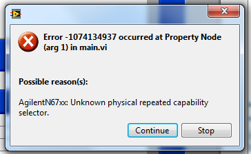
n6700 parameters of voltage/current query via the mode property
I try to back the tension of the query and the current settings on the power modules in my N7600 chassis. I use this routine. I get the following error. It works very well with my E363x feeds
It's working now. I had to add the 'active' channel to the node with the voltage and current demands. I got it that way originally, so I don't know why it didn't work. Maybe I still had the old broken driver... thought that I had a new already when I tried. It is in any case, everything works fine now. I can share what physical supply is used with MAX without the code never know the difference.
-
Current measurement using the NI 9203
I'm trying to measure an output 4-20 mA, with a flow meter. I try to use DAQmx and in channel DAQmx-create, there is a shunt location option. Do I have to specify this setting if I use NI 9203?
Thank you!
You don't have to specify a location for the NI 9203 shunt resistance. If you do not specify one, choose 'default' or 'internal '. The 'external' option is for the configuration of a device of voltage (the NI 9205, for example) and plug in an external resistor. You will be able to read the voltage at the terminals of the resistance and DAQmx would return data in amperes and do the math for you.
-
Measure the time between two digital pulse
Hello
For a non-critical calendar application, I need to measure the time interval between consecutive TTL pulses, ranging from the order of 0.5 s for a few seconds, with a low accuracy of +/-10-50ms. The interval being measured varies between the rising edge of the first pulse and the front of the next and so on.
I have several input lines I need to deal with. Because it's a critical machination low cost, I don't want to use digital counters for each line, so I work with an acquisition of data USB6008 and have connected the input rows TTL on the digital inputs of the device. Avoiding will be sufficient.
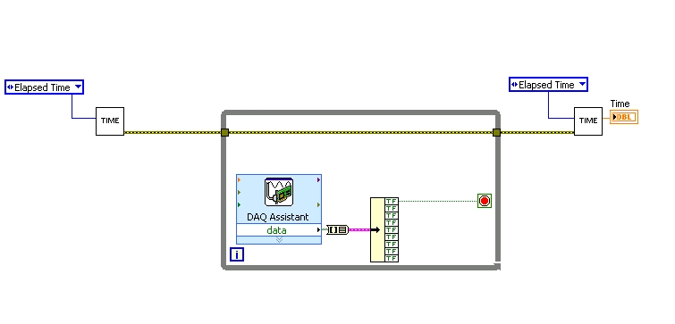
I found a good example of VI on discussion forums that does almost the same thing, only it uses instead of the DAQ Assistant user input. The VI works including the time the program going on in a while loop. I replaced with the DAQ Assistant output (a channel) user input in the hope that it is still work.
When I run the program in "run once" mode, it seems to work perfectly. However, in "continuous run" it measures only a very small interval, probably just the time between two samples. I think it has something to do with the help of a while loop in combination with the DAQ Assistant. Anyone who has any suggestions how to solve this problem?
Thank you!
OK... first of all, you should never use the button "run continuously. I wish that NEITHER would be to eliminate it, but told me that it is sometimes useful for debugging. If you want your program to run over and over again, use a while loop with a stop"" button.
If I'm reading your code correctly, you make your initial moment, and then collect data from data acquisition. When one of the channels is "T", you stop your loop and the end time of capture. (By the way, why you convert your table to a cluster? Why not just index the appropriate channel in the table directly?)
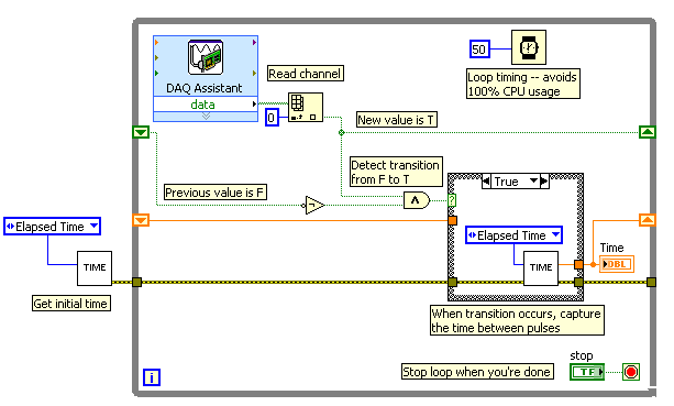
Since you want to capture the time between two consecutive pulses, you need to know when a transition has occurred... i. e when your digital line went from F (no pulse) to T (pulse start). This will give you your forehead. Right now, all you're doing is looking for a value T - so you have no way of knowing if you are looking for to the previous impulse again, or a new impetus. You also burn 100% of your processor with the way you have your programme in place.
You need a small loop delay so that your VI is not 100% of your hogs CPU time. Given that you can live with an accuracy of 50msec, what I suggest that you use.
See attached picture for you give an idea of how to implement. He will probably need some refining operations, but it should point you in the right direction.
I hope this helps.
Maybe you are looking for
-
I have four accounts on Thunderbird gmail, everything worked fine but now all of a sudden I can't send all messages to any account, it only shows 'connecting to smtp.googlemail.com'but nothing happens. I can receive emails normally and even see the e
-
I get this error ssl_error_rx_malformed_alert when you try to load a Web page
I was living a pop up by "salus" and trying to get rid of him, I reinstalled Firefox. Since then, I'm unable to open Web pages. Only, I get the above error. I found out a way around it's first open CCleaner and click the button "online help", by doin
-
Add module bluetooth to dv4-2155dx, possible?
Just got a dv4-2155dx to replace my dv4-1435dx, because I love this laptop. It does not come with bluetooth, however, so I was wondering if I can add it myself. I had the role of HP parts, but I just wanted to know if anyone knows if there is even
-
HP 2000-2c22DX Notebook PC: HP 2000 - black screen after login
Hi, I have a hp 2000 laptop that has a black screen after I login. I have used F9 or ESC tab and follow the directions shown by others with the same problem, but nothing has changed. Sometimes he goes to the site of Regclean Pro I installed when I go
-
HP service is the worse there are no. DRIVERS for OSX10.9
HP service is the worst, he saw a new printer and still can use wisely because there is no drivers for OSX 10.9, solder a HP!