33120A pulse mode
I am trying to configure mode pulse on Agilent 33120 A using RS - 232. I finally understood that the relevant screw on instrument driver does NOT support the 33120A!
Anyone have any ideas?
Do not know why some smileys have been inserted in the text.
So here's a screenshot (sorry the large size).
Ben64
Tags: NI Software
Similar Questions
-
HP psc 2110: a pulse mode, nothing works well in this mode for my psc 2110 all-in-one.
Get this second puosating soundevery, and the printer is frozen. In the past I have reset in unplugignthe power and then hoding the arrow buttons cancel and right and the pluging in the power sometimes it works.
Hello @johnny1936,
Welcome to the Forums of HP Support!
I understand that the printer HP PSC 2110 all-in-one is frozen and making a frequent pulsing noise. I would like to help you to solve this problem today. Currently, there is probably a problem with your product, power or a Firmware programming problem occurring within your printer. Can I please you follow the steps below to isolate this problem and fix it.
Step 1: Check of power:
Please connect your all-in-one PSC directly into the wall outlet for power. Power strips and surge protectors can cause your printer for lack of power and will not work properly. Once your printer is plugged directly into the wall outlet test your printer to see if the problem is resolved. If the problem persists, proceed to the next step.
Step 2: Power Reset:
- With your printe r WE, please unplug the power cable from the back of your printer
- The power cord unplugged for 1 minute
- After 1 minute the back power cable plug in
- Your printer should start up on its own
Once the printer lights please test your product in order to confirm that the problem has been resolved. If the problem persists, your product may experience a failure of Firmware. The Firmware is the internal "brain" of your printer. It determines what your printer is and how your printer it. If the firmware is corrupted in your printer, it may cause performance problems. Normally, I would have you update the Firmware on your printer. If the problem persists after the update is complete, will allow us to complete a programming reset the printer. However, due to the age of your printer there is no Firmware updates or resets the programming. Therefore, a replacement product may be necessary if this problem persists.
Please reply to this message with the result of your troubleshooting. If the problem persists, please let me know if you see all the solid or flashing lights or message board on your printers. I look forward to hear from you!

-
Inspiron 1545 will not be turned on, seeing as a pulse mode 'sleep'
My Dell Inspiron 1545 has been sitting for a while, and when I went to plug it and try to use it, it will not turn on. All I got is a lightweight "forced" power as when it is in sleep.
I recently replaced the battery and the charger, because the original battery was shot and the shipper was in horrible shape. I also replaced the power Jack earlier because the pins inside were bent and the laptop has been no power.
I had used successfully the laptop for a while after the replacement of these parts, but now it won't turn. If I'm on battery, AC or both, it only flashes / impulses when I press the power button. When I pressed the power button, it stops.
What's not here? I checked and re-seated memory strips, also to test slot machines and nothing has changed.
Hi CARCRAZY98,
Thank you for the update.
Well, when you turn on the system, if you hear the rotation of the fan and HARD drive, turn it on, connect an external monitor and check if there are any which screen.
Reinstall the cmos battery and check when possible. Given that the system is powered from the adapter, at this stage, I do not suspect the adapter. Also, remove the memory and disconnect the HARD drive and check if the system turns on and beeps - indicating a lack of HDD / memory.
As stated in my previous post, if all else fails and the indications do not change, I suspect the motherboard.
Let us know if you have any other questions.
-
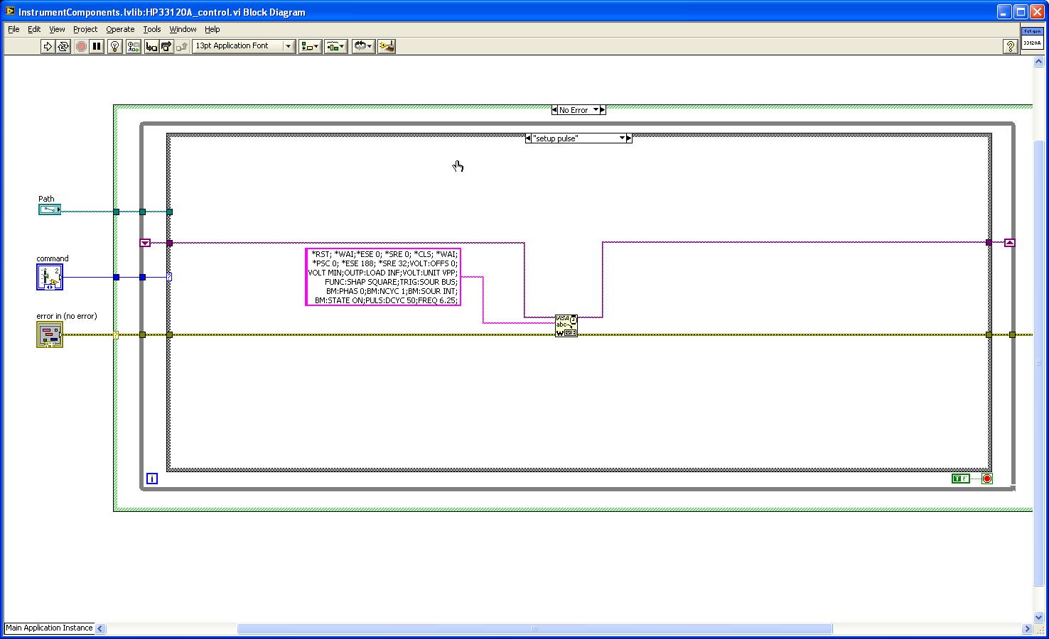
HP/Agilent 33120 A pulse, use burst mode
Hello
I'm trying to trigger a pulse of demand on from a HP 33120 A function generator.
The pulse must be a 0 - 5V simple, with frequency/period adjustable ramp. I was able to get as much of the FG by use of burst mode and trigger manually on the front panel. Now, I would like to get the same functionality from a LabVIEW VI.
Although there is a driver for the device, the burst feature is, unfortunately, not applicable to the model that I use. I found a similar problem on the forums and follow the code of the SCPI provided in the answer with some of my own humidification (http://forums.ni.com/t5/LabVIEW/33120A-Pulse-Mode/td-p/1088106).
Unfortunately, my VI does not produce the same waveform as the manual release out of the front panel. It hovers at the offset value and gives me a few square wave to zero when I run the VI. Square waves are spaced oddly and I usually see 4-5, even though I specified 1 cycle in VI. The 33120A reading, I feel that this is of my do not turn off the previous signal but, if this is the case, I can't understand how I would do.
I start to move away from using only the drivers by changing the code of the SCPI, but I'm still pretty new to this. Would appreciate some advice on what could be the problem. I modified my original VI twice; Once configure only the FG burst wave parameters manually and one just put up the waveform with no shine. The first don't not gave me much better results and the works of the latter very well so I'm back to the question of thinking are in transition.
I enclose the original VI (b) with the two modifications to the case where (c and d).
Hope to hear from you,
Yusif Nurizade
Edit: Burst chain should say TRIG: SOUR BUS instead of EXT, although neither works.
Or you have the appropriate firmware in you function generator?
Have you checked this with Agilent? -
at the same time production and measuring the pulse
Hello everyone,
I'm generates a pulse for specific time. Now, I want to measure within the same daq card. I've done Vi for him but he has an error. I have USB daq-6343. I enclose my Vi here.
The problem is I am able to get pulses generated at PIN 6 PFI but reading Vi watch time-out error.
I plugged the wire between PFI 1 pin and PFI 6 pins on the DAQ card.
So please suggest me what to do to eliminate this error.
Thanks & best regards,
I just looked at your original vi, I had looked only at the most distant (corrected) a previously. I don't see a good reason to read timeout error you have immediately. Record of an error timeout on your attempt reading suggests that the code was executed without error so far, including the beginning of the generation of pulses. That would leave wondering on physical cable connection or possibly some undesirable side effects caused by your cleanup code when you three States a PFI lines.
The other issue was my suggestion to leave DAQmx Timing.vi outside of the configuration string entirely for cases like this where you only want to build a single pulse. To be honest, it's a habit & practice I adopted a long time ago. I thought one of the reasons was that the finished pulse trains required a minimum of 2 samples. A bit of test code showed me that it isn't true, if my memory tells me there was a time when it * used * to be true. I don't remember if I have errors or if the task has chosen to generate 2 pulses with just a warning, or something. I just remember that, while he was working on a module that was supposed to be able to produce any number of pulses from 1 to N, I found that I wasn't actually able to support the case of 1 pulse by asking just 1 sample over sample mode.
* Anyway *, the other reason to avoid sampling over for a single pulse mode is that in the past, this would consume actually 2 counters on DAQ cards. Generated the pulse (s) while the other was a help that triggered the first to control the number of generated pulses. It was unnecessary as you could * also * generate a single pulse leaving the DAQmx Timing.vi out of the config, a method that used only 1 meter.
X-series cards (like yours) don't consume over 2 programmable counters of the user to generate finite pulse trains, so the lesson I learned a long time ago and was trying to convey is perhaps not so important in your case. I recommend it even if you know that you will always generate a single pulse, simply because he considered the standard way to generate a single pulse (as seen in examples of navigation).
-Kevin P
-
Implement a timer on an SMU-6361
I need to implement a timer by using one of the counters/Timers on a SMU-6361 Multifunction DAQ module. I don't find any help on the web view OR to implement the timers. I guess to study the manual of the X series that I would use the single pulse generation with trigger function. I need assign a clock shipped as SOURCE, assign an entry PFI as the DOOR (Start Trigger), set the value of the impulse for my timing delay, define the pulse width and assign a PFI as the OUTPUT Terminal. However, I can't find any information about what nidaqmx functions I would use to perform this action.
Can anyone address this operation?
wkesling3 wrote:
All examples of OR are for the meter entry tasks. Everyone says to use the example of counting digital event that needs to be changed to make it work.
It of weird, is it some sort of filtering option in CVI? I have examples of ANSI C meter output to:
C:\Users\Public\Documents\National Instruments\NI-DAQ\Examples\DAQmx ANSI C\Counter\Generate Pulse
I took out the DAQmx calls from the code you have written so that they are easier to see on the forum:
DAQmxCreateCOPulseChanTicks (EchoTaskHandle, chan, "", "/ PXI1Slot3/20MHzRefClock", idleState, initialDelay, lowTicks, highTicks);

DAQmxExportSignal (EchoTaskHandle, DAQmx_Val_CounterOutputEvent, "/ PXI1Slot3/PFI3");

DAQmxCfgDigEdgeStartTrig (EchoTaskHandle, "/ PXI1Slot3/PFI4", DAQmx_Val_Rising ");

DAQmxStartTask (EchoTaskHandle);
I see only a few small changes to make:
20MHzRefClock is not a valid terminal, you probably want to use 20 MHztime base.
Instead of DAQmxExportSignal, I use DAQmxSetCOPulseTerm. The output is already on one of the default PFI lines (depending on the meter) and setting the output of an explicit PFI line will change the output terminal. Export the output event counter I think sends the output of a second terminal (I'm not positive if flippant... calls might actually be equivalent, but DAQmxSetCOPulseTerm is most commonly used).
You define the task to be redeclenchables if you intend to trigger the exit several times (DAQmxSetStartTrigRetriggerable). You could alternatively, you can restart the task after each trigger in software, but this is inefficient and you will have several ms downtime compared to the redeclenchables task which will be immediately re-army after the release completed (within 10 seconds of ns anyway).
wkesling3 wrote:
Hi John,.
When (or why) would be the next function call used when the output is already

    defined in the DAQmxCreateCOPulseChanTicks()   function call.

//

  DAQmxErrChk (DAQmxSetExportedSignalAttribute (taskHandleDist,

                                                                    DAQmx_Exported_CtrOutEvent_OutputBehavior, DAQmx_Val_Pulse));
The meter has in fact two different modes.
"Toggle" is the default value for the tasks of the meter output, in which the output of the meter will switch to the opposite value when it reached number of terminals (how a new value is loaded into the account register and the meter begins to count down). So in your case, 'Initial period' will be loaded first, then when the meter lorsque le compteur atteint reached TC output will rise to high and "High Ticks" is then loaded into the registry. When the counter reaches TC again the output will switch down (and in your example pulse, the output will stop - in the generation of pulses multiple 'Low Ticks"would be then responsible).
"Pulse" mode the meter emits only a short pulse (I think 2 ticks long timebase) when it reached TC. It is used by default on meter entry tasks (for example the meter output can serve as an event to detect overview for the tasks of entry conditions). Exit tasks can be configured to "Pulse" too, but in this case the names 'high ticks' and the ' weak ' are unsuitable because the output signal is high only for a very short time (they would be more appropriately called "interval 1" and "interval 2" or something like that).
Most people just use the default behavior and explicitly set the output behavior unless they have a reason to change the default (which is rare).
Best regards
-
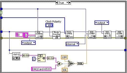
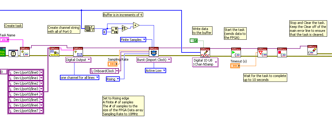
Problem with traditional DAQ passage to DAQmx using NOR-6534
I'm moving the traditional following of DAQ code to DAQmx:
This code is used to send data to program a FPGA using a PCI OR-6534 DIO. This code works like a charm, but when I try to write the equivalent code using DAQmx (in LV 8.6 as well) it does not work. I don't get any errors, but the FPGA do not program.
The General procedure is as follows:
The value of all the lines on the Port exit 0
Set up the mode of transfer to low Active
Write the data in the buffer
Send the data using the internal clock of 10 MHz of the 6534 (6533 is no longer used, but the code was never updated)
Wait until the output is made
Disable the task
In DAQmx I configured as such:
Any ideas on what has changed in DAQmx or what I am doing wrong?
Looking at your code traditional DAQ once more, he is actually setting up handshaking vs just a straight sample clock. The Config VI Mode with the "clock polarity" setting is not a sample generated at a certain rate clock, but instead, it's a protocol handshaking attack or the trailing edge. TDAQ had much more flexibility with what DAQmx and some handshaking protocols are not transferable to DAQmx completely.
So when you say the configuration of your device in TDAQ bass Active transfer mode, I don't see what is happening in the code TDAQ. It's really a negotiation protocol of unknown polarity (given that you use a control and I don't see the default value in the public Service).
You can try to determine which protocol handshake TDAQ you use first, then determine if there is an equivalent for DAQmx. The three modes that cannot be transferred are level ACK, tip, or long pulse modes. These have ACK leading REQ, which is not possible for DAQmx to manage. You can read more in the user guide for the 6534 and starting on page 3 and 4 are the comparison of the different modes of handshake.
Then move forward options are do not migrate or to download a beta driver TDAQ, if you perform the migration for the purposes of the compatibility of the OS.
Hope this helps, let me know what other spawn of this. Thank you.
-
I have an external clock 20 MHz connected to APFI1, I want to use as a sample of 16 clock inputs digital. Unfortunately I wanted to divide this clock by 2 at the hardware level, but I forgot in the mad rush to get out the Board. Now I find myself with a problem! Map NIDAQ I use (NOR-6289) can enjoy digital inputs as soon as 10 MHz so just sampling and decimating in the software is not an option. In addition, it seems that counters cannot treat ticks is less than 2, so low, I can divide the external clock down by 4. The only option I see at this point is to use the external clock as a trigger for a free counter running on the clock of 80 MHz. The counter would then serve as clock for digital inputs. However, I want to retain the flexibility to change the external clock and not constrained by the software.
I was encouraged at the beginning of this thread, but unfortunately it does not seem possible with digital inputs.
Y at - it anyway to divide this by 2 clock and use it for digital inputs?
Thank you
Drew
Hi Drew,
I think you can probably find this works using an output meter task set to pulse Mode instead of toggle (default). Here is an example that shows how to configure the meter in this way. I have posted just the example, you may need to wait a few moments before the transfer is completed.
Best regards
-
Generate certificates for use with the VMware SSL certificate automation tool
Hello
I am trying to use the tool to automate SSL certificate. Our vCenter Server is configured in pulse mode. When I'm trying to generate the request (CSR companies) for Single sing - on (SSO) of certificate signing, option 1 is to provide the FULL domain name. I want to know what domain name FULL should I provide the name of the node or virtual.
Also I will try to use this tool for other components like updatemanager, inventory service, service of vcenter server, web client. Have experience how to use this tool?
Thank you
I successfully replaced certificates for all services. I used the FQDN of the virtual name and not the name of the node to generate the CSR. Thank you
-
Pulse synchronization on 5422 in Standard Mode, how?
For a trigger, I would like to output a pulse of synchronization on each period (PFI0 AND PXITrigX) on a 5422 FGEN in Standard Mode.
I can do it in Mode AWG, but how to do it in Standard mode?
Found this example of community who resolved the task

I didn't know that events of marker work also in standard mode...
-
Apple Watch continues to pulse messureing
My Apple Watch stops the messuring pulse about 3 Minutes after the beginning of a workout.
in Helthapp, I see a messure pulse after the start up to 3 Minutes, then it stops frequently.
The next point of messure of pulse is if I stop the workout, it'll be 1 or 2 hours later.
Any idea?
Hi Michael
On your iPhone, in the application of the watch, go to: Watch My > Workout - if it is currently enabled, disable power saving Mode.
Otherwise, the following steps may help:
- Close all open applications on your iPhone to them and then restart your iPhone and your watch:
- To close open applications on your iPhone: click twice on the Home button, and then drag upward on each preview of the app.
- Both devices turn off together, and then restart your iPhone first:
- To turn off your watch: press and hold the button side until you see the cursor off the power; slide it to turn off.
- To reactivate: press and hold the side button until you see the Apple logo.
- If this does not help, try next disconnect and rematching of your watch:
- The app shows on your iPhone shows backups automatically, including a new when the unpairing via the application.
- Choose to restore your watch (backup restore) when provided the opportunity during the whole. Most of the data and settings will be restored, with a few exceptions (for example cards Pay Apple, access code).
- Cancel the twinning of your iPhone - Apple and Apple Watch Support
- Set up your Apple Watch - Apple Support
If the problem persists, I suggest you contact Apple Support (mail service may be available) or make a booking Genius Bar in order to have your watch checked under warranty:
- Close all open applications on your iPhone to them and then restart your iPhone and your watch:
-
Satellite Pro L300 - 1FJ PSLB9E enters mode "sleep" instead of power
Hi all...
I have a laptop Toshiba Satellite L300-1AF, and I noticed this issue only recently.
It works and everything it ok it runs Windows XP Pro SP3 and works normally, however when I stopped it closes down and runs out of windows and the amber standby LED starts to pulse if it is in standby mode.
Then, I turn to it now and back again with the power button to stop a pulse.So in short, it seems that windows closes down successfully, but then the laptop goes into sleep / standby mode instead of turning it off. Anyone know why this is happening?
Hello
Are you sure that you have chosen the Option: Power OFF instead of the Mode standby?
As much as I know Win XP does not additional option to configure SHUTDOWN on the start menu.But you should check this:
Go to control panel-> power options control
Here in select it a feeding area, click Change plan settings
In the advanced settings window, click on the + next to the power buttons and lid.
Now, you will see the options available.
Under the cover option and power buttons, click on the + sign next to the start menu power button.
Then click on the parameter and choose stop down. -
How can I turn off the sleep mode in Apple Watch the temporary?
Guys,
My wife is studied for his chiropractic studies and tried to use Apple Watch as a timer so that it checks the patient's pulse, but she is unable to use the watch due to the sleep mode. Plu wake screen is 70 seconds as described in settings. Is it possible that it can disable temporary screen wake up so she's doing the pulse testing?
Justin
Version: Watch OS 2.1
Hi Justin
It is not currently possible to disable the sleep of the Configuration screen. The longest time that the screen can stay awake without further interaction is 70 seconds (subject to activating first the setting you describe).
-
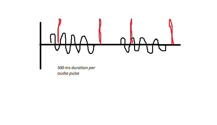
Triggering off the coast of beginning of Pulse Audio in question DAQmx...
Hi guys,.
First of all, it is more a matter of software than hardware, so I didn't post this specific question in the multifunction DAQ card...
So I'll try to trigger an acquisition finished off the start of a pulse audio, however I have audio sync issues, due to the fact that it can be started before my VI runs. As noted below, the audio is generated and pulsed for 500ms on and 500 ms off the coast, and between these periods, a digital pulse is generated this way (shown in red). I have a problem to stay synchronized, due to the fact that I samples finished for 1 second of a data value, and if the USE EEG is faster than me, I can catch the pulse audio at Midway, rather than at the beginning.
I'm trigger analog outboard of a sound signal of 50mV and capturing two audio channels simultaneously and consistently captures 3 digital channels when they receive the trigger of the beginning of analog input trigger reference digital edge. If digital are slaves and audio is the master in this configuration. The point of this is to get a delta timed material at the time rather than use the timestamps of windows.
As I said, I use an Analog Edge Trigger Start to start my purchase, what triggers the digital task Digital Edge Start Trigger to start as well. How can I make sure that I start at the BEGINNING of a new pulse audio if I get out of sync, I can't understand this logic... Analog edge goes off just when it goes to the specified level, but maybe it's at half way through the 500ms pulse, so this is my problem...
I need to be a trigger to start because I do 55 000 this test iterations in a QMH Prod/consumer model and need relaxation to be redeclenchables and start-up is only redeclenchables.
The variability in timing you see at points 2 and 4 somewhat dictate against the possibility to set up a re-triggering precisely timed by the hardware configuration. I think that you need to abandon the idea of making repeated sampling finished back to back and switch volleys in a mode of continuous acquisition and treatment.
To help with this, I aim to capture the moments of digital via meter rather than DIO pulses and be ready to give up the acquisition rate noise much (if necessary) given that you said that your main concern is to distinguish between ON and OFF.
I must configure the counter to use the Digital pulse as a sample clock and use the sample clock signal HAVE the "time base", i.e. the signal which the edges will be counted and buffered in memory. This will give you 2 samples per second instead of 5 M and the values of the counter at these sampling points is the index in your AI data which occurred impulses. Pretty neat and clean. Just be sure to start the task of counter in front of the task to HAVE it.
-Kevin P
-
Calendar synchronized with Diuble pulse using PCI-6601
Hello
I'm trying to run a PIV of Labview 8.5.1 system using a PCI-6601 map at the exit of the signals for the laser and the camera.
This requires a line for the camera, one for the FPS (first removal of pulse) and one for the Q-switch.
The difficulty is in the need of a double pulse on the Q-switch for mode double frame PIV.
The distribution box that I use is not one NOR one and I don't have access to 3 outputs four against, otherwise, quite simply, I would use a BNC t with two pulses slightly staggered junction.
I have access to a BNC-2110 timing box, but I think it is not compatible with the PCI-6601 and have no funds to buy a BNC-2121 right now.
I managed to create a double pulse by using one of the counters with a finite number of impulses set to 2 and then stop the task, then run this in a timed loop.
However, it is then based on the software, which is not precise enough for the application, and I can't figure out how to get the timed loop to run from the time of 20 MHz of 6601 map base.
I could be missing something obvious here, or perhaps is more annoying? I'm fairly new to DAQmx.
Thanks in advance
Joe
Dominic makes a good point about the operating system, but really the best solution is to use the hardware timing when possible.
I have set up an example that shows how you can implement different sets of impulses finished using the calendar of the Commission. It requires the use of two meters, but then again a generation of impulses finished the fact (on the 6601).
Communities: Generate several Cycles pulse finished using two countersAlternatively, if you have another signal that you want to use to trigger each set of pulses (rather than to specify a rate so that they occur as in the example above), counters on a 6601 are redeclenchables then you can use the external signal to trigger the generation over time and time again without having to stop the task in the software.
Best regards
John
Maybe you are looking for
-
I live in South Africa and have one of the retina MacBook Pro 15 "(mid - 2012). A message appeared recently advising "Condition: replace now." We approached Apple in Cape Town (South Africa) providers and received two different answers on what need
-
How can I change the zoom or the size of my e-mail
I use fire fox and suddenly my email everything went very small and I know that there is a way to enlarge the email from 50 to 75% of printing etc I can't find how to get to the police how can I find a way to expand my e-mail This has happened Just o
-
Re: Should I buy the NB200 or not? Help, please
Hey guys! I think buying the Toshiba NB200 netbook. I would ask you advice me whether it would be a good choice for my first netbook.I would like to know if the installation of windows 7 is the netbook a little faster or not. Also I've heard that the
-
Get rid of Parental control on my guest account
Why can't get rid of parental control on my guest account! It is said you can not set up parental controls for the guest account and yet when I try to connect it throws up of all these parental controls! I watched & tried and tried again to fix it.
-
can't get the downloads to update my system
I made a new clean install of win 7 pro 32 bit sp1 have noticed after a few days, no updates have been received. Lhen go you to Windows Update and look for the updates there simply display nothing 'check updates' has been doing since yesterday.