acquisition of data... read entry with highlighting of execution
Hi all
I'm reading a device entry after generating the tension, and I am confused about the difference in the results when
1. I use the running highlight

2. without highlighting the execution

3. once the beginning vi to generate instead of after vi vi. Also can someone explain why?

Tags: NI Software
Similar Questions
-
Acquisition of data reading zero intermittently
I use 3 analog inputs of an acquisition of data USB-6009 to monitor and record the temperatures of my system. This running VI constantly perform 1 read per second and periodically saving the values drop. Everything works very well for a few weeks or even months, until that data acquisition shows suddenly have a value of zero. unpluging the acquisition of data and by him plugging back in solves the problem. Therefore, I assume that this is due to the DAQ or maybe the USB communication being refreshed power cycle that I get the correct values again. Any ideas on how to test for the cause of this problem or preventive measures, can I take?
I was the closing of thought and could help restore communication at the end of each day.
Oh, and I'm using LabVIEW 2010 on Windows 7.
Disable the 'power save feature' Windows 7 where it randomly disables your USB hub. Go to Device Manager and go to USB hubs then the power settings.
-
Acquisition of data reading too fast in the loop For
I am trying to characterize a system with a VI that sets the speed of a motor, waits 7 seconds go upward, then take 200 readings calculates their. The sampling frequency is 20 Hz, with 200 samples, it should take 10 seconds. The program then loops through another iteration, sets the speed of the motor using the next value and the process repeates.
Although the first iteration works well, for some reason, something goes wrong in all iterations after that, because you have to read for only 2 or 3 seconds instead of the 10 that she should take. I don't know if it's some kind of memory problem or maybe something else. VI is attached. Thank you!
That would be because you are using the acquisition mode = "continued acquiition" not "N sample (on request)" so while you wait seven seconds you take samples
-
Acquisition of data high-speed with time stamp
I am acquiring data at a fairly fast speed (5 to 25 kHz) for a few seconds and then writing in a spreadsheet file. Is there a way to set up so that it displays the time stamp for each data point instead of just the data point number?

Of course. Change the type of data returned by DBL 2D to 1 D wave form. This is doen by clicking on the polymorphic selector or right-click and choose 'select the Type '.
-
Generation and acquisition at the same time, acquisition of data USB-6356
Hello
I have a VI how is able to read entries with a USB DAQ-6356 and I use a generator of signals 'Agilent 33522 A '. I want to generate and acquire with the acquisition of data.
In fact it works but not well, the frequency is not very stable and does not stop the 2nd loop with 1 (2nd is generating, 1 is Acquire).
Thanks in advance

P.S my VI isn't a state machine true because I need to fight against it at the moment.
OK, so you're at 3 ms/s in writing and reading at 1.25Ms / sec and you wonder why he has a little difference in the frequency set? Ideally, you want to read and write to share a sample clock but by selecting at least the same frequency clock (or one that is one multiple of the other) would go a long way to fixing this source of your error.
The second source of error: you generate a contineous waveform. unless you select 'whole number of cycles' there is a discontinuity when the end is reached at an arbitrary phase and the phase is reset to zero at the beginning of the wave. DAQ assistant writing can "Use Waveform Timing" to adapt its sync settings to the dt waveform and the number of samples.
-
do you need a power supply to the current entry with data acquisition or 9265
Hello I just receive the NI 9265 Daq for research in my lab. I'm trying to present entry and display it on an oscilloscope. I don't get anything. I did some research on the internet, so my question is do you need a power supply to the current entry with data acquisition or 9265?
Read the data sheet. Clearly on the first page is a sentence which reads "the NI 9265 requires 9 V to 36 V external power.
-
Read for the acquisition of data entries are overwritten
Hey there
I have a Daq reading input in a spreadsheet file
Data acquisition was told that one is supposed to have some time a loop around it and I cannot get it to run without one, so good
But my main problem is that it means that it replaces my written file each time that the loop repeats
He also asked me to choose the file to write in several times
How would I go about fixing this?
Thank you
Yes, you can convert digital to the chain, check the attached VI. I recommend you to go through the basic materials of LabVIEW and also play with example of NEITHER which comes with LabVIEW. Remember not to use the attached example and the acquisition of data, always use separate loops.
-
Input module of data acquisition can be read by two or more LabVIEW vi at the same time % 3F
I use the DAQ palette in LabVIEW to read the virtual channels of the input data acquisition module. I've done several VI who read many entries of three modules of simulations. The problem appears when I run two or more VI´s reading entries from the same virtual module (for example. first.VI module 1 input ai0 and second.VI bed ai0 entry module 1 bed), when this happens the next errors are shown:
Error-50103
Platform AND Services: The specified resource is reserved. The operation could not be performed as indicated.
and
Error-200022
Resource requested by this task has already been reserved by another task.
It's worrying because I want to get the DAQ chassis and some modules, but if this problem is present with physical equipment my application may be unnecessary. This means that entry module only can be read once at the time?
I m using global variables in each Subvi to share data with main VI, however, I found the solution in a different way... I just changed to single channel and dbl sample playback mode, so I Don t need to clean up the task of reading in my subVI´s, the zeros isn´t problem here, and the six subVI´s work at the same time!
Thanks for the tips!
-
merger acquisition of data to read input data 2 or several at once
Hi all
I'm using or usb-6009 more then 2 incoming signals.
the problem is that I can't read 2 signals at the same time. 1 my daq assistance will be apeared to be error.
so, how can I set the .vi (attached) so that he could read 1 more signal since the acquisition of data?
I also tried to separate daq support but error. I also try to merge the two signals with a different port (a1 and a0)
can anyone help?
Thnx for the reply
Frankly, I went through all the tutorials and looked for answers in the forum and the conclusions I have difficulties to understand the technical language... I have been looking for everywhere labview users and found someone who could guide me carefully... im have desperately need guidance... not to give up hope trying to find the answer, but a sort of feedback that is giving advice that you need to take the driver's seat... FYI... I take the driver's seat... that look like a real Nubian now needs help...
is there any order step by step so that I could add channels more 1 1 daq help?... I've done it before, but it occurs.
for example, I want to create channel 1 to read the value of the resistance and channel 2 for playback of tension... but what happened when I create more than 2 channels, it is be will configure this channel only 1 located in the block diagram... both channal will give only data for the value of the resistance.
Sorry for my broken English.
-
Difficulty to read the instrument of series and acquisition of data simultaneously.
Greetings,
I have some trouble getting my VI read from my data acquisition and instrument of the series at the same time. If I run the Subvi simultaneously (i.e. subANG runs in a window and subVEL is running in a second window) both return the correct values and behave as I expect. However, if I call the Subvi in a society mother VI and try to run them both in the same loop structure subANG gets stuck and won't be reprobed with a signal change.
I also tried to use a stacked sequence or plate to separate the execution of subVEL and subANG, but I still get no response to subANG.
The point is is that, if I run Parent.VI in a single window and then creates a copy of subANG (call it '--copy' or other) and run it in a second window, Parent.VI behaves properly and will update the readings as they appear in '--copy '.
I enclose 3 files.
(1) subANG.VI - this bed an an inclinometer RS232 signal. The signal is refreshed every 10ms or more.
(2) subVEL.VI - this bed raw tension of a channel on the acquisition of data, calculates the average then that converts into a pressure difference and finally a speed based on the pressure and temperature inputs.
(3) ParentVI.VI - they simply call and displays the Subvi
My guess is that it's a buffer problem, but I am confused. Someone out there in Labview Earth knows why this might be happening? Suggestions welcom.
It is not an instrument of series. It is a UEI PowerDAq with their typical A/D and the cable.
I found away to make it work by placing subANG and subVEL in some time different loops side by side in ParentVI.
-
Need help get data with the most recent date of entry into
Hey guys;
I need help with fine tuning a query to get the one with the most recent implementation.
Here's my current query:
/**********************************************
Select sge.seal_group_id,
SGE.equipment_id,
SGE.effective_date
of seal_group_equipment EMS.
seal_group sg
where equipment_id = 48801
AND EMS. SEAL_GROUP_ID = SG. SEAL_GROUP_ID
and sge.end_date is null
Group of sge.equipment_id, sge.seal_group_id, sge.effective_date
After having sge.effective_date = max (sge.effective_date)
******************************************************/
Which produces the following results:
SEAL_GROUP_ID - EQUIPMENT_ID - EFFECTIVE_DATE
25-48801 - 01/01/1993-00: 00:00
11730-48801 - 22/08/2003 08:42:11
What I really need, is to show only the line with the most recent date of entry into
I hope someone can help
Thank youMAX will not work because the SEAL_GROUP_ID could depart. I would say analytical:
select seal_group_id,
equipment_id,
effective_date
from (
select sge.seal_group_id,
sge.equipment_id,
sge.effective_date,
RANK() over (partition by equipment_id order by effective_date desc) r
from seal_group_equipment sge,
seal_group sg
where equipment_id = 48801
AND SGE.SEAL_GROUP_ID = SG.SEAL_GROUP_ID
and sge.end_date is null)
where r = 1;
Keep in mind if two records have the same effective_date, they would both appear.
Note: query above has not been tested, since there is no script provided.
-
Here is my sensor
Pressure sensorHere's the DAQ data sheet:
Here are my issues:
First of all I don't know what is LO and HI exactly in the DAQ 9219 material.
Second, I don't know what pin code I should connect the DAQ sensor signal wire. PIN 4 or 5 pin? The sensor has three pins, and I guess I should connect the other two wires to the power supply.
Thirdly how to calibrate the sensor. In labview choose voltage in the wizard?I'm pretty new in this acquisition of data and I need your help.
Thank you
Hi SilasIII,
Hmm well 3 sons are probably on the ground, the power and the return signal. The datasheet for the sensor says:
First of all, you need to know which model you have (4-20mA, 0 - 5V or 0-10VDC). HI refers to the return signal, LO essentially means the land of the food that feeds the sensor. Then, you must get the 13-30 VDC supply. I don't think this should be too complicated and can be a simple wall DC power. You can learn how to create a custom in DAQmx scale. I hope that this is a starting point.
Kind regards
Eric
-
Acquisition of data and filtering on FPGA
Hi all
I have trouble to design a FPGA program for acquisition of data and filtering.
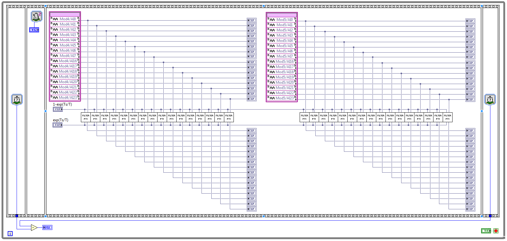
I have two NOR 9205 modules configured to work in terminal mode of DIFF, i.e. There are 32 entries this program must read every Ts seconds. (Ts is the time discretization, i.e. during the period of loop)
With respect to the digital filter, I implemented a possible simple filter with transfer function G (s) = 1 /(1+sT), which is part of the field of discrete-time equal to y (k) = a * u (k - 1) + b * y (k-1), where u is the original signal, and there is filtered signal. The coefficients a and b are equal to: a = 1-exp(-Ts/T), b = exp(-Ts/T), and T is the time constant of the filter (usually T > 5 * Ts).
The implementation of main program for the acquisition of data and filtering are:
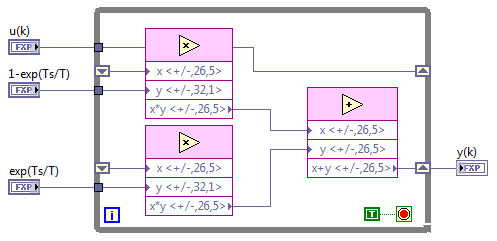
This application is for the digital filter:
However, the problem is that this program cannot take the FPGA resources on cRIO-9114, and Yes, I tried to define the criteria of compilation for the area. I also tried to implement the multipliers in digital filter as lut and DSP, unfortunately without a bit of luck.
Because I don't have that much experience in programming of FPGA, someone has any suggestions how to improve this code to adapt existing FPGA resources?
Best regards
Marko.
Hey Norbert_B,
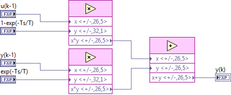
I managed to solve the problem. First, I changed the reentrancy of Preallocated incoming execution clone to not reentrant execution. As no reentrant VIs have States, I had to use the node of the feedback to the main VI to get u(k-1) and y(k-1). Another important thing is to choose Ignore FPGA reset method in the node of the properties of FPGA implementationfeedback, since in this case, the feedback node uses less resources.
Here is the new main program VI:
And here's the 'filter' VI:
Thanks for the help!
Best regards
Marko.
-
The data read into the buffer HAVE lack samples at the beginning
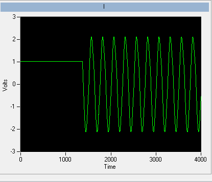
I use a box USB-6251. The program implements two channels of AI (read I and Q) on a single task and one channel on another task. The channel uses the ai\SampleClock as its clock, so that both are synchronized. C creates a digital pulse periodic rising edge (a clock basically) which is used as a trigger on an external function generator. The signal from the unit after going through some material, external signal processing is ultimately what is read by the channel of GOT it.
We know from the relevant signals, they seem to be correctly synchronized scope. IE, the analog signal to read arrived on the channel of the AI of the acquisition of data more or less instananeously when the trigger is activated. If there is a delay, it is of the order of microseconds.
However, when I read in the buffer of HAVE (repeated FiniteSamples), waveform, I always come back has a section of samples at the beginning that seem to be returned of the first actually read data-point (see attached image). This delay is of the order of milliseconds (it varies with each series).
I want to totally eliminate this delay. The signal should be a sinusoid which begins to sample 0 and is continuous through until the last sample read.
I put the code below.
Installation program:
Create analog read the task
analogReadTask = new Task ("analogReadTask");Create the virtual channel for the component I
analogReadTask.AIChannels.CreateVoltageChannel (initParams.AddrI.ChannelAddress, 'I', AITerminalConfiguration.Differential,-4, 4, AIVoltageUnits.Volts);Create the virtual channel for the Q component
analogReadTask.AIChannels.CreateVoltageChannel (initParams.AddrQ.ChannelAddress, 'Q', AITerminalConfiguration.Differential,-4, 4, AIVoltageUnits.Volts);To set the clock for the analog readings
analogReadTask.Timing.ConfigureSampleClock (string. Empty, initParams.SamplingRateHz, SampleClockActiveEdge.Rising, SampleQuantityMode.FiniteSamples, Totalechantillons);Create the mult-channel drive
analogReader = new AnalogMultiChannelReader (analogReadTask.Stream);
analogReader.SynchronizeCallbacks = false;pulseWriterTask = new Task ("pulseWriterTask");
Creating a digital output channel that provides the trigger to the U/S system
pulseWriterTask.DOChannels.CreateChannel (initParams.AddrUsTrigger.PortLineAddress, "US trigger", ChannelLineGrouping.OneChannelForEachLine ");
pulseWriterTask.Timing.ConfigureSampleClock ("/ SampleClock/AI/Dev1", initParams.SamplingRateHz, SampleClockActiveEdge.Rising, SampleQuantityMode.ContinuousSamples, samplesPerPulse);
pulseWriterTask.Stream.Buffer.OutputBufferSize = samplesPerPulse;
pulseWriterTask.Stream.WriteRegenerationMode = WriteRegenerationMode.AllowRegeneration;pulseWriter = new DigitalSingleChannelWriter (pulseWriterTask.Stream);
pulseWaveform = new DigitalWaveform (samplesPerPulse, 1, DigitalState.ForceDown);
pulseWaveform.Signals [0]. The States [0] = DigitalState.ForceUp;analogReadTask.Control (TaskAction.Verify);
pulseWriterTask.Control (TaskAction.Verify);
From reading:
analogReadTask.Start ();
Start writing the digital pulse, however it will not start
until the AI/SampleClock begins, so implicitly synchronizing the two tasks
pulseWriter.WriteWaveform (pulseWaveform, true);analogReader.BeginReadWaveform (Totalechantillons, readerCallback, analogReadTask);
Result (should be a sinusoid from end to end)
Always seems to solve these problems, shortly after their validation.
The problem has start the digital task AFTER the analog task. In the small delay between the two lines of code running, read analog had already begun, and so some of the impulses of the AI/SampleClock were missed by the task. The order of departure between the two tasks of switching solves the problem.
-
Analog multichannel peculiar read problem with PCI-6014 - hardware problem
Hi all
I see some very special behaviors with a 6014 when I do a multi-channel analog playback. I am revamping of existing code to a customer, which implies the passing of the traditional DAQ in the DAQmx. Traditional DAQ does not use a system based on the tasks, my client was in the process of reading clocked by the software for only one channel at a time, depending on what signal was of interest to both. (application is a series of tests on a control PCB who will interface with some hardware, checking the answers and tensions and others)
When I rewrote the application using DAQmx, I created a single task that contains all of the analog inputs of the map (AI0:15). When I am interested in a particular signal, I indexed the channel since the reading chart data. The strings that contain the actual data are 0, 1, 3, 4, 5, 6, 7, 13, 14 and 15. All channels are NRSE.
One of the signals of interest lights AI7.
When I connect the AI7 signal with an oscilloscope, I read 2.5V - which is exactly what I expect to see.
When I read AI7 using MAX, I read 2.5V.
When I read AI7 by itself using a single channel DAQmx reading (i.e. 1 Samp 1Chan or 1Chan N Samp), I read 2.5V.
When I read AI7 simultaneously with all the channels that have a greater number of channel (i.e. AI8-15), I read 2.5V.
When I read AI7 simultaneously with any channel that carries a lower channel number (i.e. AI0-6), I read 2.34V.
?????
For example, if I read AI0:15, I read 2.34V on AI7. If I read AI0:7, I read 2.34V. If I read AI7:15, I read 2.5V. If I read AI7:10, I read 2.5V. If I read AI6:7, I read 2.34V. And so on. Any combination of playback channel which includes results AI0 AI1, AI2, AI3, AI4, AI5 or AI6 during a misreading on AI7.
All channels read because they are supposed to, no matter what channel is included in the job. AI7 is the only one that illustrates this behavior.
I wrote code for the acquisition of data for 10 years now and I have never seen anything like this before. The behavior is consistent. I am sure that it is a hardware problem with the Special Commission that I use. That's the advice of my customer, I don't know when they bought it, but I think they have had for years. I doubt that ever, it has been calibrated.
I guess it's more I'm curious than anything else - what on earth would cause this behavior?
I'll tell my client to replace the card, if really I just asked my own knowledge.

Maybe you are looking for
-
Media center problem with Qosmio G35-650 - error message
Hi all I have a problem with media center on qosmio g35-650.When starting live TV, an error message is displayed and written "enforcement failed Please restart your computer again. If the problem persists contact again with your hardware support"It w
-
Red negative amounts manufacturing
How can I change the format of 'currency' or create a new format for negative amounts in numbers appear as bold and red font?
-
Means - This is a foro Público para no publicar nunca privada como el correo electronico o phone numbers information Ideas: Programs that are having problemas con Error messages 80007005 he intentado solucionarlo muchísimas veces pero lo didn't he he
-
Whenever I'm trying to run a program another window pops up saying 'open with '.
This problem occurs with all the programs that I try to open it and I often have to right-click and then click "start" to start the program. According to me, that it has something to do with file extensions (sorry if this isn't the technical term I'm
-
Reference Dell R510 TR blocca durante the reinstalllaizone di windows 2008 Server [MS]
Buonasera, Ho una R510 dell server. STO tentando di reinstallare macchina ham he con cd it software original Bolivia con hardware. (windows 2008 server 64-bit) my TR blocca ad un certo punto installaizone. Ho riprovato eliminando the partizioni e ric