Acquisition of data reading zero intermittently
I use 3 analog inputs of an acquisition of data USB-6009 to monitor and record the temperatures of my system. This running VI constantly perform 1 read per second and periodically saving the values drop. Everything works very well for a few weeks or even months, until that data acquisition shows suddenly have a value of zero. unpluging the acquisition of data and by him plugging back in solves the problem. Therefore, I assume that this is due to the DAQ or maybe the USB communication being refreshed power cycle that I get the correct values again. Any ideas on how to test for the cause of this problem or preventive measures, can I take?
I was the closing of thought and could help restore communication at the end of each day.
Oh, and I'm using LabVIEW 2010 on Windows 7.
Disable the 'power save feature' Windows 7 where it randomly disables your USB hub. Go to Device Manager and go to USB hubs then the power settings.
Tags: NI Software
Similar Questions
-
Acquisition of data reading too fast in the loop For
I am trying to characterize a system with a VI that sets the speed of a motor, waits 7 seconds go upward, then take 200 readings calculates their. The sampling frequency is 20 Hz, with 200 samples, it should take 10 seconds. The program then loops through another iteration, sets the speed of the motor using the next value and the process repeates.
Although the first iteration works well, for some reason, something goes wrong in all iterations after that, because you have to read for only 2 or 3 seconds instead of the 10 that she should take. I don't know if it's some kind of memory problem or maybe something else. VI is attached. Thank you!
That would be because you are using the acquisition mode = "continued acquiition" not "N sample (on request)" so while you wait seven seconds you take samples
-
merger acquisition of data to read input data 2 or several at once
Hi all
I'm using or usb-6009 more then 2 incoming signals.
the problem is that I can't read 2 signals at the same time. 1 my daq assistance will be apeared to be error.
so, how can I set the .vi (attached) so that he could read 1 more signal since the acquisition of data?
I also tried to separate daq support but error. I also try to merge the two signals with a different port (a1 and a0)
can anyone help?
Thnx for the reply
Frankly, I went through all the tutorials and looked for answers in the forum and the conclusions I have difficulties to understand the technical language... I have been looking for everywhere labview users and found someone who could guide me carefully... im have desperately need guidance... not to give up hope trying to find the answer, but a sort of feedback that is giving advice that you need to take the driver's seat... FYI... I take the driver's seat... that look like a real Nubian now needs help...
is there any order step by step so that I could add channels more 1 1 daq help?... I've done it before, but it occurs.
for example, I want to create channel 1 to read the value of the resistance and channel 2 for playback of tension... but what happened when I create more than 2 channels, it is be will configure this channel only 1 located in the block diagram... both channal will give only data for the value of the resistance.
Sorry for my broken English.
-
Difficulty to read the instrument of series and acquisition of data simultaneously.
Greetings,
I have some trouble getting my VI read from my data acquisition and instrument of the series at the same time. If I run the Subvi simultaneously (i.e. subANG runs in a window and subVEL is running in a second window) both return the correct values and behave as I expect. However, if I call the Subvi in a society mother VI and try to run them both in the same loop structure subANG gets stuck and won't be reprobed with a signal change.
I also tried to use a stacked sequence or plate to separate the execution of subVEL and subANG, but I still get no response to subANG.
The point is is that, if I run Parent.VI in a single window and then creates a copy of subANG (call it '--copy' or other) and run it in a second window, Parent.VI behaves properly and will update the readings as they appear in '--copy '.
I enclose 3 files.
(1) subANG.VI - this bed an an inclinometer RS232 signal. The signal is refreshed every 10ms or more.
(2) subVEL.VI - this bed raw tension of a channel on the acquisition of data, calculates the average then that converts into a pressure difference and finally a speed based on the pressure and temperature inputs.
(3) ParentVI.VI - they simply call and displays the Subvi
My guess is that it's a buffer problem, but I am confused. Someone out there in Labview Earth knows why this might be happening? Suggestions welcom.
It is not an instrument of series. It is a UEI PowerDAq with their typical A/D and the cable.
I found away to make it work by placing subANG and subVEL in some time different loops side by side in ParentVI.
-
Read for the acquisition of data entries are overwritten
Hey there
I have a Daq reading input in a spreadsheet file
Data acquisition was told that one is supposed to have some time a loop around it and I cannot get it to run without one, so good
But my main problem is that it means that it replaces my written file each time that the loop repeats
He also asked me to choose the file to write in several times
How would I go about fixing this?
Thank you
Yes, you can convert digital to the chain, check the attached VI. I recommend you to go through the basic materials of LabVIEW and also play with example of NEITHER which comes with LabVIEW. Remember not to use the attached example and the acquisition of data, always use separate loops.
-
Here is my sensor
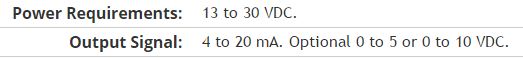
Pressure sensorHere's the DAQ data sheet:
Here are my issues:
First of all I don't know what is LO and HI exactly in the DAQ 9219 material.
Second, I don't know what pin code I should connect the DAQ sensor signal wire. PIN 4 or 5 pin? The sensor has three pins, and I guess I should connect the other two wires to the power supply.
Thirdly how to calibrate the sensor. In labview choose voltage in the wizard?I'm pretty new in this acquisition of data and I need your help.
Thank you
Hi SilasIII,
Hmm well 3 sons are probably on the ground, the power and the return signal. The datasheet for the sensor says:
First of all, you need to know which model you have (4-20mA, 0 - 5V or 0-10VDC). HI refers to the return signal, LO essentially means the land of the food that feeds the sensor. Then, you must get the 13-30 VDC supply. I don't think this should be too complicated and can be a simple wall DC power. You can learn how to create a custom in DAQmx scale. I hope that this is a starting point.
Kind regards
Eric
-
Why are sometimes has data from WriteMeas Read zero instrument drivers?
I have a labview program to control the motorized turntable to rotate and measure the light intensity using photometer Konica Minolta CS - 100a.
Photometer is connected to the PC via RS - 232.
Program works great again, data are zero in the decusse format (see table below), the ok status shows error all the time, for line with zero data error code is nothing, and for lines with data, there is a "107367629" error code
I also enclose the program and a few photos, could someone help?
Angle Intensity x There error code 0 340.1 0,443 0,405 107367629 10 0 0 0 0 20 345.99 0,443 0,405 107367629 30 0 0 0 0 40 343.33 0,443 0,406 107367629 50 0 0 0 0 60 335.73 0,443 0,406 107367629 70 0 0 0 0 80 323 0,443 0,406 107367629 90 0 0 0 0 YBU wrote:
Hi all
Could someone suggest a solution for this problem?
Thank you very much
Sorry man, you know most of us here have jobs and help people on this forum for our time free nothing expected in return.
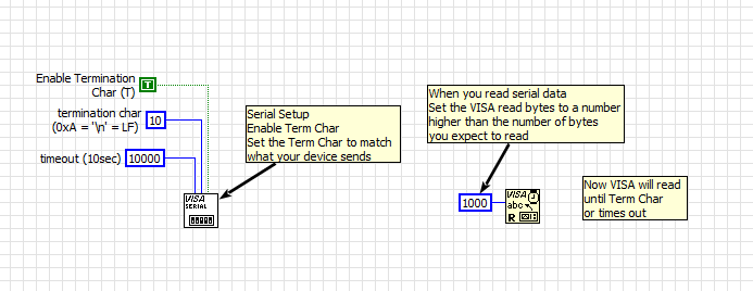
The first question is how the serial data is formatted? Have a stop character? IE is the data sent by the device always ends with a return character or new transmission line? Device series more for this.
-
Generation and acquisition at the same time, acquisition of data USB-6356
Hello
I have a VI how is able to read entries with a USB DAQ-6356 and I use a generator of signals 'Agilent 33522 A '. I want to generate and acquire with the acquisition of data.
In fact it works but not well, the frequency is not very stable and does not stop the 2nd loop with 1 (2nd is generating, 1 is Acquire).
Thanks in advance

P.S my VI isn't a state machine true because I need to fight against it at the moment.
OK, so you're at 3 ms/s in writing and reading at 1.25Ms / sec and you wonder why he has a little difference in the frequency set? Ideally, you want to read and write to share a sample clock but by selecting at least the same frequency clock (or one that is one multiple of the other) would go a long way to fixing this source of your error.
The second source of error: you generate a contineous waveform. unless you select 'whole number of cycles' there is a discontinuity when the end is reached at an arbitrary phase and the phase is reset to zero at the beginning of the wave. DAQ assistant writing can "Use Waveform Timing" to adapt its sync settings to the dt waveform and the number of samples.
-
The data read into the buffer HAVE lack samples at the beginning
I use a box USB-6251. The program implements two channels of AI (read I and Q) on a single task and one channel on another task. The channel uses the ai\SampleClock as its clock, so that both are synchronized. C creates a digital pulse periodic rising edge (a clock basically) which is used as a trigger on an external function generator. The signal from the unit after going through some material, external signal processing is ultimately what is read by the channel of GOT it.
We know from the relevant signals, they seem to be correctly synchronized scope. IE, the analog signal to read arrived on the channel of the AI of the acquisition of data more or less instananeously when the trigger is activated. If there is a delay, it is of the order of microseconds.
However, when I read in the buffer of HAVE (repeated FiniteSamples), waveform, I always come back has a section of samples at the beginning that seem to be returned of the first actually read data-point (see attached image). This delay is of the order of milliseconds (it varies with each series).
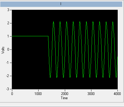
I want to totally eliminate this delay. The signal should be a sinusoid which begins to sample 0 and is continuous through until the last sample read.
I put the code below.
Installation program:
Create analog read the task
analogReadTask = new Task ("analogReadTask");Create the virtual channel for the component I
analogReadTask.AIChannels.CreateVoltageChannel (initParams.AddrI.ChannelAddress, 'I', AITerminalConfiguration.Differential,-4, 4, AIVoltageUnits.Volts);Create the virtual channel for the Q component
analogReadTask.AIChannels.CreateVoltageChannel (initParams.AddrQ.ChannelAddress, 'Q', AITerminalConfiguration.Differential,-4, 4, AIVoltageUnits.Volts);To set the clock for the analog readings
analogReadTask.Timing.ConfigureSampleClock (string. Empty, initParams.SamplingRateHz, SampleClockActiveEdge.Rising, SampleQuantityMode.FiniteSamples, Totalechantillons);Create the mult-channel drive
analogReader = new AnalogMultiChannelReader (analogReadTask.Stream);
analogReader.SynchronizeCallbacks = false;pulseWriterTask = new Task ("pulseWriterTask");
Creating a digital output channel that provides the trigger to the U/S system
pulseWriterTask.DOChannels.CreateChannel (initParams.AddrUsTrigger.PortLineAddress, "US trigger", ChannelLineGrouping.OneChannelForEachLine ");
pulseWriterTask.Timing.ConfigureSampleClock ("/ SampleClock/AI/Dev1", initParams.SamplingRateHz, SampleClockActiveEdge.Rising, SampleQuantityMode.ContinuousSamples, samplesPerPulse);
pulseWriterTask.Stream.Buffer.OutputBufferSize = samplesPerPulse;
pulseWriterTask.Stream.WriteRegenerationMode = WriteRegenerationMode.AllowRegeneration;pulseWriter = new DigitalSingleChannelWriter (pulseWriterTask.Stream);
pulseWaveform = new DigitalWaveform (samplesPerPulse, 1, DigitalState.ForceDown);
pulseWaveform.Signals [0]. The States [0] = DigitalState.ForceUp;analogReadTask.Control (TaskAction.Verify);
pulseWriterTask.Control (TaskAction.Verify);
From reading:
analogReadTask.Start ();
Start writing the digital pulse, however it will not start
until the AI/SampleClock begins, so implicitly synchronizing the two tasks
pulseWriter.WriteWaveform (pulseWaveform, true);analogReader.BeginReadWaveform (Totalechantillons, readerCallback, analogReadTask);
Result (should be a sinusoid from end to end)
Always seems to solve these problems, shortly after their validation.
The problem has start the digital task AFTER the analog task. In the small delay between the two lines of code running, read analog had already begun, and so some of the impulses of the AI/SampleClock were missed by the task. The order of departure between the two tasks of switching solves the problem.
-
Operating system: Windows XP
Hardware: PCI 6259
Terminals used: PFI0 and PFI2
Counters used: Ctr0 and Ctr1
IM developing an application for the acquisition of data where timed loop synchronization source comes from my PFI2 (using the string A of an encoder). IM basically trying to acquire data based on the number of ticks from my encoder. For the synchronization source, I use counter 1 to capture the rising edge and have the loop time-acquisition of data. At the same time, Im using the counter 0 to count the number of rising edges so I know exactly in what tick data was acquired. PFI0 and PFI2 are connect to channel A of the encoder.
Questions:
Timed loop acquires data at each tick, because when I discover the data (text) file is missing count of my encoder value. Is it because there is a limitation on the Windows operating system? I used a noculars to measure the frequency at the maximum rotation of the channel encoder and 6,757 kHz. All solutions?
Also, is there anyway I can route the source channel internally an encoder to generate synchronization source instead of using another counter? I have attached my VI.
Hello
All the samples that you acquire will be read by LabVIEW in a sequential manner. Figure 4-21 on the M-series on page 80 (4-34) shows that you will acquire all the samples you request all channels that you enjoy in sequentially.
-
Acquisition of data and filtering on FPGA
Hi all
I have trouble to design a FPGA program for acquisition of data and filtering.
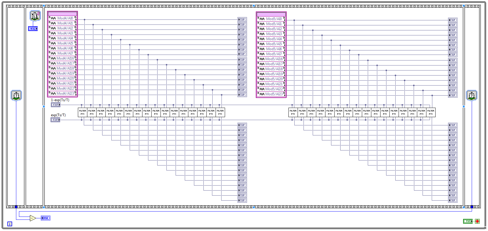
I have two NOR 9205 modules configured to work in terminal mode of DIFF, i.e. There are 32 entries this program must read every Ts seconds. (Ts is the time discretization, i.e. during the period of loop)
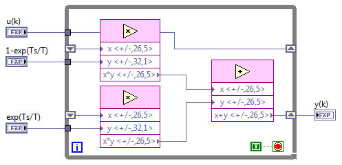
With respect to the digital filter, I implemented a possible simple filter with transfer function G (s) = 1 /(1+sT), which is part of the field of discrete-time equal to y (k) = a * u (k - 1) + b * y (k-1), where u is the original signal, and there is filtered signal. The coefficients a and b are equal to: a = 1-exp(-Ts/T), b = exp(-Ts/T), and T is the time constant of the filter (usually T > 5 * Ts).
The implementation of main program for the acquisition of data and filtering are:
This application is for the digital filter:
However, the problem is that this program cannot take the FPGA resources on cRIO-9114, and Yes, I tried to define the criteria of compilation for the area. I also tried to implement the multipliers in digital filter as lut and DSP, unfortunately without a bit of luck.
Because I don't have that much experience in programming of FPGA, someone has any suggestions how to improve this code to adapt existing FPGA resources?
Best regards
Marko.
Hey Norbert_B,
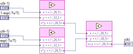
I managed to solve the problem. First, I changed the reentrancy of Preallocated incoming execution clone to not reentrant execution. As no reentrant VIs have States, I had to use the node of the feedback to the main VI to get u(k-1) and y(k-1). Another important thing is to choose Ignore FPGA reset method in the node of the properties of FPGA implementationfeedback, since in this case, the feedback node uses less resources.
Here is the new main program VI:
And here's the 'filter' VI:
Thanks for the help!
Best regards
Marko.
-
How to block a number of cardboard/acquisition of data to a particular program?
Is it possible to "connect" a DAQ card serial number with a Labview design/program?
For example, PCI-6601 is a serial number 12345 and I write a program (called ProgramABCD) to the acquisition of data, I want to "tie" / "bind" 12345 and ProgramABCD together, so that ProgramABCD will not work on an another PCI-6601 (unless I have change the serial number corresponding to ProgramABCD for the new PCI-6601).
Thank you.
Hi celine,.
You could read the serial number of the device programmatically using a node property and then based on that, decide whether to terminate or continue the program. See this link: http://digital.ni.com/public.nsf/allkb/92F3F7C79579FA238625718700764F9D?OpenDocument
However, if this will be distributed to the end user as a .VI file not an executable, then the end user could always go into the code and change/modify it so that it can use different devices with it.
-
Use two assistants for the acquisition of data at the same time
Hello
I want to read multiple data channels of analog inputs on my DAQ hardware. However, when I try to create two separate data acquisition assistants for each entry, it gives an error saying "is reserved for the specified resource. The operation could not be performed as indicated "." Can't use two assistants for the acquisition of data at the same time?
I have to add different channels in the same assistant DAQ? I tried, but I couldn't separate the data in different graphs.
How does this work?
Kind regards
Allard
You can't have multiple tasks of the same type (in this case inputs analog) on the same device. Just so having 1 DAQ Assistant read all your channels and separate your channels for individual transformation.
-
Hello
How to find the undo tablespace read data.
How to find the data read from the data file.
any select statement read to redo log or not. I think not, is this correct
Thank you
regardinguser3266490 wrote:
Hello
Thanks for the reply, what amazing one explanation. A DBA, I want to find activities of the user if their statement read buffer or thinl file.i data that the method is not suitable to find each session.do you have nothingWell, you have to remember two things. One, there may be any time where the disk IO would be completely zero. At any time, certain data would come the disc as the buffer cache is a circular cache that flushes unused data after certain periods of time. Also the data that will be the consultation: for the first have no choice but to come from the disc. Then there would always be a disk activity that will be there.
Second, hmm OK do not discuss each other, it can confuse you.
As a dba, you would not normally be too worried about user IO level. What you should look on, it is that in the system, all disk i/o are not too high which may lead to the question that your cache configurations do not correctly!
HTH
Aman... -
Satellite A300D-135 - BIOS - System Configuration data read error
After starting a Satellite A300D-135 laptop computer, the following error message appears:
3070M extended RAM passed
512 KB of L2 Cache
System BIOS with a shadow
Video BIOS with a shadow
ATAPI CD-ROM: TSSTcorp CDDVDW TS-L632H
Fixed disk 0: TOSHIBA MK2546GSX
Initialized the mouse
ERROR
System Configuration data read errorPress
to resume, installation After pressing F1 the machine starts Windows, very well, but the error message is quite irritating, while it comes with a loud BEEP
I tried the following things so far (in that particular order):
-Load BIOS default
-Flashed the BIOS with the latest version of the BIOS (2.80) for this type of model
-Reinstalled windows with HARD drive formatAll the these did not work.
I saw the same message appearing on several places on the internet (on different laptops with a Phoenix BIOS in common), but so far I have not been able to find a working solution.
It might me a hardware problem, but all devices (vga, soiund, lan, wifi, usb, hdd) seem to work perfectly under Windows, so this does not seem the question). Another solution that is mentioned in some forums, replace the battery. But because the phone keeps time correctly I don't think it's the case either.
Any ideas?
Kind regards
GJHello
The POST (power on self-test) BIOS checks and detects errors on the motherboard.
I think it has something to do with the hardware on the motherboard problem.
I doubt that you can solve this if update of the BIOS and the BIOS default settings didn't change that.What to say; I think that the technician of the ASP should run tests to check what's wrong or what cause this I think it is question of s mobo.

Maybe you are looking for
-
Cannot get my Contacts to sync between iPhone 6s and Mac book pro
I tried to synchronize contacts with cloud. I tried to disable the contacts of the cloud on the 6s and the Macbook pro as instructed. Does not. Contacts are created on the phone and some on the Mac, this could be the problem? This is ongoing and I'm
-
I have no cursor blinking in the box where I type
I have no cursor blinking in the box where I type. If I start typing the whole box moves to the top of the page and you can tap into it then.
-
Satellite Pro 4200 - annoying click speakers
Hi all I have Satellite Pro 4200 and it works well but has a click on the speakers. It's OK while surfing but on downloaded music there are about 5 quick cycle repeat modes. It does same start-up jingle. Is this an easy useful solution or not? I can
-
Mouse Microsoft Wireless Presenter 8000 and Toshiba Bluetooth Stack
Some of the specific features of the MS Bluetooth Mouse will not work with the latest Toshiba Bluetooth Stack: magnifying glass, digital ink... The other functions of this mouse (and the remote control works too) work perfectly. The magnifying glass,
-
My samsung 500 GB HDD ejected automatically
When I connect samsung s2 500 GB HDD in my laptop (a vista x 64) it detected normally and after a few seconds the pilot ejected himself and repeating the process. Sometimes it works normal but not for long I checked "disable computer alow device" in