actuation of the valves
Hello
I used before Labview but I don't consider myself as an expert. I am trying to operate two solenoid valves with the acquisition of data USB 6525. The valves need 12Vdc for 20-30ms to operate, once spent no extra power is needed to maintain the valve in place. I want to use this DAQ because it has internal relays of SS I want to control using LabView. I want the Labview block diagram to let the user choose when to open and close the relay using milliseconds (this is very important). Here are my questions:
(1) how to connect the valves to the USB 6525 DAQ with the external power source. (to check)
(2) I need help create the block diagram, I don't know where to start
Any help will be greatly appreciated, I tried to solve this problem for more than a week.
Tags: NI Hardware
Similar Questions
-
Hide an item based on the valve
Hi All-
I have 2 valves (think clamshell has and valve B in this case). When the form appears Valve A a text element should display. When the form shows the text element of valve B do not show (it should hide the form). I know that I have to give a condition for this article, but I'm not sure what to give.
Appreciate your help,
Kind regards
Nani (Version 3.2 of the Apex).Novice,
For your article, there is an attribute of type condition. Set it to the "value of the point in Expression 1 is NULL". 1 expression of the value = "VALVE_B" (or whatever the name of the page for valve b element).
(I couldn't say if you mean valve or value)
See you soon,.
Janet Tyson -
Motor current and the current valve using CAN interface.
Hello
I want to order current engine and valve for some time. The currents of control valves and engine are different for different times, they also have different repetation for test times.
My problem is how can exploit all the valve and engine at the same time.
I use NOR-X-net, I have attached a capture, control valves and motors signals are the same message PSD1 - x 605.
The valve are engine operation is also attached to the file xlx.
Thank you.
Rahul.
Hello
Please suggest me that how can I run motor and valves separately, both of the soul, I have attaced a program in which I am running engine and set of valves, but I want to run them with time to different repetation and check the valve and engine based on time, current diffrently.
Thanks in advance.
-
Best configuration for the control of solenoid valve
Hi all
I'm really new with everything regarding controllers or the relay so that any help would be much appreciated.
I want to control 5 valves (Web site) with the following characteristics:
Rated voltage: 12 or 24 VDC, available voltage fluctuation: 10% of energy consumption (when 24V nominal voltage): 1.5W (0.06 A)
I want to use LabView to control. In a similar position, I knew I would need a digital camera I/O driver relay and a generator of 24V.
I was thinking of using these:
NEITHER 6501
Relay driver (uln2003)and a 24V generator.
Is it enough to order the valves with LabView or do I need something else?
Thank you very much for your help!
Ilan
Yes, this combination should suffice. The ULN2003 is designed for exactly this type of application, and works well.
Usually in English, we refer to the power supplies when we talk about devices to convert AC line voltages to lower DC voltage.
In addition to LabVIEW, you will need a driver for the USB-6501 DAQ. Under Windows, it will be DAQmx. On Mac or Linux, the dirver is DAQmx Base. The driver is a separate LV facility, although it can occur on the same disks.
Lynn
-
Control valve tank with plots and twists of the water
Hello everyone!
This is my frist real project. And I am in love with this program so far!
I have a little problem. Here it goes:The project of the University which has been given to us is to simulate a (entrance OPEN/CLOSED valve) water tank filling and emptying (output range of 0 to 100% valve), but with a few twists. It is done by the command to the movement by the following formula: flow rate [%] = position of the valve [%] * current water height [%]. (The output valve takes values in percentage from 0 to 100% giving the voltage digital output of 0 volt to closed(0%) or 5 volumes for open(100%), the strange part, is that the digital output can have a value of 0 or 1, so the position of the valve is "simulated".) And the supply valve (valve entrance) water can be open or closed (if 0 or 5 volts)
-Sequences cannot be used (only one for initialization and cleanup can be used)
-When the water level reaches 10% of the max height, LED lights, the output valve closes and the input valve opens. The LED is on until the button is pressed. The output valve cannot be opened until the water height is greater than 50%.
-When the water level reaches 90% of the max height, LED lights, the entrance valve opens. The LED is on until the button is pressed. The output valve cannot be opened until water height is less than 50%.
-There are two mode selectios:
Control by hand: the person sets the position of the valve in percent and the flow is calculated by the formula and displays on the screen.
Automated: Every 2 seconds the program assigns the place valve so that the current is constant, it is the value by the person.
-(N'ont pas gottern ici encore) ESD (Emergency shutdown switch) the when is pressed both the entry and exit valves are closed. The entrance valve cannot be oppened up to the RESET_IN key. If the program is 'Control in manual mode' output valve cannot be opened until the RESET_OUT touches. In which case the output valve is in "Auto" mode, it does not start work until the RESET_OUT touches.
My main problem here is the fact, I cannot use sequences and nested, then the loops do not work. The aqusition of data stops until the inner circle loop ends and I need both work. Especially for the 50% rule.
I've been hitting my head for a few days and still couldn't come up with a solution.
I have attached the VI.
Tips are welcome!
For the time being the outputs inputs/digital analogue are a simulation (when the time comes the USB-6008 material is used).
There is some things that confuse me (as if the valves are percentage, from 0 to 100%, or digital, 0 or 1), but regardless, it's a detail.
Review the task and consider what you want to do and that the "States" the system may be in. [This with a pencil and paper, do not open LabVIEW yet...]. The description of your problem learn you something about the transition from one State to another. Here is a thought exercise:
Suppose you are in a "State". Let the system to "do its thing" for a second, which could involve the water flow. At the end of the second re - evaluate your state - it changed? Continue to do this...
This model of 'something' is called a State Machine and LabVIEW has some very good examples and tutorials on the creation and use. The important things to do before you make your coding is (with the pencil and paper) decide on your statements, decide on the transition rules, and then you are ready to code.
There are different ways to build a State Machine in LabVIEW, but the basic idea is quite awhile (to keep things moving along, a shift register which includes the current state, usually represented as an enumerated, Type whose values are simply the names of your States (made for a very mnemonic routine) and a Case statement whose power is the State of the shift register that contains the code to achieve this) particular State of loop, including the implementation of transitional rules (which can cause a new State on the registry to lag when it comes out of the investigation of the case).
A great exercise. Strive to keep your block diagram on a single computer screen by making use of the screw subgroup chore (as the management of changes in the water level based on the current water level and "States" (which here means 'values') two valves). Once you understand the 'Idea' State Machine, you should be able to write the code for this problem quite easily.
Bob Schor
-
We send 5v data acquisition using a voltage generator. Hook us it up to a voltmeter and see 5V. When connect us the generator voltage to a valve "normally open" parker, the voltmeter indicates .14V. It seems that when we connect the two sons of the valve for the voltage generator, the son act as pattern. We want to control the voltage flowing to tap through Labview. We checked the wires to the valve and they work very well, because if we send a constant 5V since the acquisition of data and put ashore, she, the voltmeter indicates 5V. Someone knows why the son act as pattern and low blood to .14V?
nsatpute wrote:
Our data acquisition is NI USB-6259. The valve requires only a 5V max and our DAQ provides up to 5V. However, after connecting the valve to the acquisition of data, the grave tension to almost 0. We start from the principle that the son somehow act as the reason, but we are not sure if this is the case.
The question here is not how much voltage the valve wants, it's the current needs of the valve. The 6259 can put only 5mA via an analog output. Your very likely tap needs much more than that. If you need to add in an amplifier circuit that can supply more current to operate your faucet.
-
How to measure the digital output of the linear actuator on USB-6009?
Hello
I am a new user of Labview and need help to measure a digital input signal.
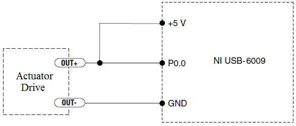
I have an actuator Bimba Original line electric with a motor continuous integrated with encoder, drive and the controller. The drive has a programmable digital output that I put as a tachometer output that emits pulses of square wave 100 per turn of the engine. I put the engine to make a total of 56 rev in 22 dry. I want to measure the speed of motor rotation labview real-time and synchronize it with a few other analog input signals. I wired the actuator for the USB-6009 case as shown below.
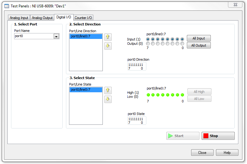
I opened the test i/o digital USB-6009 Panel and fix all the lines of port 0 as inputs. However, when I click on start and run the actuator, p0.0 led flashes, as indicated below.
Shouldn't the led blink in response to revolutions of engines?
I want basically to collect the drive pulse signals and convert them in rpm on labview.
ahsan2 wrote:
I have it wired correctly?
It would help if you do not attach the HIGH signal. Remove the + 5V in the circuit.
-
The timeslice time/block mismatch, although everything is the value
Hi, I want to control an actuator to a valve with a potentiometer is adjusted manually or automatically in a PID loop. In my view, we can select the signal using the module "time slice", as in the example of "WaveFormGenerator."
However, I get an error of "mismatched length info or block of time...". ». I compared all signals run with synchronization of time of size and 'driver' block 'global '. And now I'm stuck. I burn time, this error is coming from? I have attached a screenshot as the piece of code examples. Thanks for all the ideas.
PS - I use DASYlab 9.0
It load and ran well on V11. What is your driver? How it is configured?
-
How to program a remote adjustent with a Laser sensor and a pressure valve
Hallo,
I'm looking for a solution set a monostable pneumatic cylinder via a laser sensor and a pressure valve.
The Laser sensor and the valve has a domain controller as a signal input/output. The position of the cylinder is controlled by the laser sensor and pressure valve schould adjust pressure as needed to get the cylinder into position.
Sample:
The cylinder schould be 5mm extended from the initial position. If a team is on the stem of the actuator pressure valve schould be able to increase the pressure in the cylinder so that the location of Rod 5mm remains approximately constant.
Thank you for a few suggenstions!

Kind regards
Manual
I guess you could use a system by which the laser sensor output when it receives the laser beam.
Something like this:
Laser has detected ==> move in the first direction
Laser (later) has detected ==> move in the other direction
Laser (later) has detected ==> move in the first direction
..........
So that it switches between two States.
Or if it is possible, you could just output intensities different laser to represent different values.
You could get the signal valve dc, translate to a numeric value, set a threshold (or an upper and lower threshold could be better) where the system is stable and doing some codes to ensure that the valve maintains the pressure inside the threshold.
The rest I think is too deep, and I guess it's to you from there

See you soon
David
-
I have a problem that I can't solve. I have a table of 6 valves that are a def type. I want to tell those who are on the use of a loop for. The for loop count is a wiring number of valves that are put to the test. I expected indicators 1 to 5 to turn it on in the example, but only 5 shows on. Can you tell me what I am doing wrong?
I just thought of it, sorry to bother you. I changed the entry to a shift register tunnel and left the tunnel to exit as last value is always connected to the indicator of the valve.
Thank you.
Metzler wrote: I don't think that your diagram without the loop will work - the original valves begin by the status of the led off. This is part of a machine to States that tests up to six valves. County of the Terminal loop is used to iterate the loop many times according to the number of valves tested.
Then use the array to initialize.

-
Timed sequences. Is this the right choice and how it works!
Hello!
I am a newbie in LV, and I am creating a VI that is able to fly a small filtration unit I have build in my engineering studies.
I have to control three magnetive valves which are connected to the Do0, Do1 and Do2 digital output on my USB 6009 MyDAQ device port.
I have to control the sequence in which the valves open / farm as to avoid damage to the sensitive som of pressure transmitters. How to program a sequence of controlled time that opens and closes the valves in the right order, and in order reverse, repeat the sequential once a user defined timing?
I have looked at the 'timed sequence' but could not find a "down to earth" description on how to use it.
Perhaps my problem is a little in general. In this case I can certainly help with precision if necessary.
I hope someone can help me with my problem. Now, I spent 6 hours looking at different tutorials without a bit of luck.
Thanks in advance
Henrik
-
How to change the Boolean flag rectangle into 2 triangles.
The notation for a valve is two triangles whose ends are touching. I want to show images of the valve as indicators Boolean - red = closed and green = open. Is it possible to change the standard indicators normally rectangular or circular shape to match the double triangle. I know you can get this result using the triangular shapes and blocking part of the rectangular Boolean value which does not resemble the double triangle shape. I don't want that since I find it difficult to group the shapes.
You have controls and indicators already available in the similar DSC Toolkit.
Or a solution, you can try is to use custom controls, check your two images in software such as paint.
Select the control that you want to customize (in you case a Boolean value) and with the right click make Type Def then Open Type def.
Copy your image to that of the State in the Clipboard, and then select the picture to import from the Clipboard and the State associated with your image in the right click menu
Do the same again for the other State.
You can also find more information about the controls customized using LabView
I hope that answers your question
-
What is the right way to use variables controlled by the two buttons and programming?
First of all, I apologize if this has been discussed before. I know not how to phrase succinctly the application, so maybe I just missed the search terms.
We have several pieces of the Labview software in the laboratory that automatically control things like the taps and heaters. Sometimes we also manually control these same things. I'm moving old NI PCI (and older versions of Labview) maps to a variable and based on compactRIO system shared network. However, I'm still not on best practices to achieve. I need to be able to have a script running at any time control panel so that I can access, for example, a valve controller (which is just a Boolean), and I need power open and close the valve by programming other scripts. I need, of course, the control panel to track the State of the valve until it opens another script, the Panel indicates that it is open, and the next push on the control panel it will close.
Historically, this has been processed using structures business to move from a "computer control" and "hands-on" with global variables that define the State of the valves. Of course, this is not recommended.
So far, I've played with the help of two variables, a status of valve and the other for the State of button. The Panel configuration then loops, reads the status of the valve and puts the State of button if the State of the valve has changed. I can do this with registers at offset or with the structures of the event, but anyway, it gets very crowded and seems inefficient. Is there a good way to do this in Labview? It seems this is a common problem, so I hope there is an easy and elegant solution that I've missed.
Variable published use shared network. Your scenario and your manual of the interface and change the variable and then shared your cRIO reads fair value and writes the appropriate values.
Now for a cool part. On your manual interface, right-click on your heart control that you want to use to control the shared variable and go to properties. There should be a data binding tab in the Properties dialog box. You can bind a control/indicator to a published network shared variable. So this button will always be attributed to the current state.
Your script should just read the shared variable before resuming to verify that it is in the correct state.
-
PID control with big delay in the process variable
Hello
My goal is to control the temperature via a valve and heat exchanger. I proceeded variable (temperature) measured from a hose. This temperature should be raised a few degrees with a heat exchanger. So basically I need to order a valve that allows the water to flow through the heat exchanger to raise the temperature to the desired level.
My original plan was to use a base PID regulation to operate the dispenser. However, it is about 0.5 to 1 minute of delay time in the temperature probe after I opened the valve, which increases the temperature. This leads to a situation where the PID regulation valve fully open during this period (trying to get the temperature rise). Then once the temperature begins to rise it fires quite quickly. PID begins turning the tap off almost immediately, but because of the time delay in the sensor, the temperature exceeds seriously. This led to severe oscillation and at worst unstable processes. I tried to adjust the PID control to "predict" the timer to close the valve in advance to minimize the excess, but failed.
I would appreciate if anyone has any ideas how to make this type of control with Labview PID functions. I also wonder if there is a better type of control procedure for this scenario as a PID control?
-Lars
This is a very common situation in the heating control, and generally PID can be adjusted to make it work. How do you do the tuning? If you do it by trial and errors, you have little chance to succeed. For a slow process with time delay, I like to use the method Cohen Coons, or similar open Ziegler-Nichols-loop method. The idea is that you temporarily remove or disable the PID. Set the valve in a fixed position and wait for the temperature to stabilize. Then, change the setting of the valve and record temperature at regular intervals data until the temperature is stable again to a new value. Use these data to get the initial values of PID using the equations provided by the tuning method you choose.
-
Valve on / off substitute in while loop
Hello
I created a simple VI to change the valves at a specific time constant.
Now, I want to replace the selection in this while loop (while the VI is running) with a perminant on or off, or disable the substitution. I'm not sure how to go about it. I created one another while loop associated with each digital output line.
Any advice?
My configuration:
Chassis OR cDAQ-9174
NI 9472 24V sourcing module.

Maybe you are looking for
-
cursor does not
-
Wireless router to modem Homeportal 1800 HG 2wire Linksys WRT54G with questions
I have the Linksys WRT54G, and I'm trying to use it as the router to my modem 2wire Homeportal 1800 HG wireless. The 2wire has four ethernet Sockets in the back marked from 1 to 4 and a telephone jack to connect to the wall for AT & T DSL service. I
-
This "blue screen" error takes place every 3 to 5 days. Any idea what's going on?
Signature of the problem: Problem event name: BlueScreen OS version: 6.1.7601.2.1.0.256.1 Locale ID: 1033 More information about the problem: BCCode: d1 BCP1: 0000000000000168 BCP2: 0000000000000002 BCP3: 0000000000000000 BCP4: FFFFF88001636735 OS ve
-
Installation with MapPoint 2011 trial issues
My attempts to install the trial version of MapPoint 2011 failed, even after helpful advice on this forum. Please can you help me with next steps. I downloaded successfully the three installation files found here: http://www.microsoft.com/uk/mappoin
-
With the help of creative cloud with Tech Comm Suite
Does anyone else have this problem as it is sure as hell Adobe can't seem to accept that they have a problem!I have a subscription to creative cloud and a subscription of Tech Comm Suite.Under the license agreement, I'm able to use subscriptions on b