Analysis of the particle pixel measurments - how to get the co - ADR of the first pixel
Hello
I'm developing some labview code to measure particles.
I'm having trouble with the analysis of the particle VI. I'm not sure what values of table, I need the table to return the co - ADR of the first pixel (more to the left the higher pixel) and also any useful information!
I joined the program, I worked on that. To test I'm loading a black bitmap with some white circles on it.
Thank you
Jack
Right click on the entry of measurement in pixels and select create constant. This will paste an empty array of metrics on your chart. Click on and select the first pixel X and the first pixel Y parameters, as shown below.

Tags: NI Software
Similar Questions
-
cumputer running on it connects to the owner, how to get cumputer to display all users first
How to get my computer to go to all users when I turn on the computer
This should do it:
- Press the Windows key + R .
- Type control userpasswords2 in the Open: box and press Enter.
- Put a check mark in the box, users must enter a user name and password to use this computer .
- Click OK .
-
the analysis on the first incorrect execution
I have the VI attached to analyze the arguments of the command line of a program I wrote.
The arguments are pre filled as they would in the real envyronment running, well I can't always count on the PN parameter in the 1nth of the table element. I am looking for the value of the PN parameter.
The first time I run the vi, it does not find the value, but each race after that which detects that the value.
Any suggestions?
Edited to add: if I change a value in the table to a different place in the table, and then run, the first time it will not find the FN, but each time, after it will be.
Edited again: addition of parse string.vi to attachments
Race condition!
Why do you use a local variable of Index instead of the wire in the loop For?
During the first run of your program, the flag is set to zero in it. This table of index uses this value as the local variable is read before the loop For ends running to write a new value to this indicator. Next time (assuming that you haven't changed any data) the value of the indicator is correct because it is there since the previous run of the VI.
-
On Mac, how to scan multiple pages to a pdf file using the analysis of the glass?
Mac OS x v10. 7, how to set up analysis of the HP Officejet 6500 multiple pages in a single pdf of the file by using the analysis of the glass?
I couldn't find the box uncheck the box to 'Save as individual file' to the Mac.
My reccomendation is to use the Image Capture in your Applications folder. Choose your scanner to the left, then click on "Show details" on the bottom.
Choose the PDF format, then check the box for "combine several pages into single file" (or similar words).
-
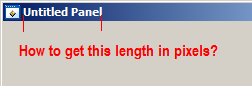
How to get the bar display of title in pixels text length?
Hello
Does anyone know how to get the length of the title bar text (in pixels) display? Just to clarify, that's what I'm looking for:
I don't see a CVI function for this. The attribute ATTR_TITLE_FONT for GetPanelAttribute (...) is only valid for the panels of the child which prevents me from using the GetTextDisplaySize (...) to get the size. Dive into the Windows SDK I can not even find an answer here. Any ideas? Thank you.
Figured out how to do this. Go to the SDK to get the font properties - is kind of nonobviousness. But once you have the font properties, you can create a font of meta in CVI, with properties, and once you have the meta font you can use GetTextDisplaySize (...) to get the size. For any future reference:
//define a NONCLIENTMETRICS structureNONCLIENTMETRICS ncmtest;//We have to set the cbSize parameter to the size of the passed structure before retrieving it
ncmtest.cbSize = sizeof(NONCLIENTMETRICS);
//Get NONCLIENTMETRICS structure
result = SystemParametersInfo(SPI_GETNONCLIENTMETRICS, 0, &ncmtest, 0);

//copy the title font name to a c-string
while(ncmtest.lfCaptionFont.lfFaceName[i] != 0)
{
    thefont[i] = (char)ncmtest.lfCaptionFont.lfFaceName[i];
    ++i;
}

//null terminate
thefont[i] = '\0';

//create meta font with title font properties.  lfWeight & 0x700 indicates bold.  CreateMetaFontWithCharacterSet() doesn't recognize DEFAULT_CHARSET so we replace it with VAL_NATIVE_CHARSET(?).
uir_status = CreateMetaFontWithCharacterSet ("TheTitleFont", thefont, abs(ncmtest.lfCaptionFont.lfHeight), ncmtest.lfCaptionFont.lfWeight & 0x700 ? 1 : 0, ncmtest.lfCaptionFont.lfItalic, ncmtest.lfCaptionFont.lfUnderline, ncmtest.lfCaptionFont.lfStrikeOut, 0, ncmtest.lfCaptionFont.lfCharSet == DEFAULT_CHARSET ? VAL_NATIVE_CHARSET : ncmtest.lfCaptionFont.lfCharSet);

//get titlebar text
uir_status = GetPanelAttribute (panelhandle, ATTR_TITLE, thetext);
//get title bar length
uir_status = GetTextDisplaySize (thetext, "TheTitleFont", &height, &width);
I have a 79 for the duration of the screenshot above.
-
How to analysis of the XML in the sql statement?
Hi friends, I have a table that contains a column of type CLOB, stores in xml format. For example, the data are like that
<Employees xmlns="http://TargetNamespace.com/read_emp">
   <C1>106</C1>
   <C2>Harish</C2>
   <C3>1998-05-12</C3>
   <C4>HR</C4>
   <C5>1600</C5>
   <C6>10</C6>
</Employees>
So how can I write the sql statement for the analysis of the data at the top
create or replace procedure parsing_xml
(
clob trans_payload
trans_dir varchar2
)
as
Start
if(trans_dir='inbound/emp')
then
insert into emp_proj
(
employee_id
last_name
hire_date
job_id
salary
department_id
)
Select t1.c1
t1.c2
t1.c3
t1.c4
t1.c5
t1.c6
from xmltable
(
XmlNamespaces ('http://TargetNamespace.com/read_emp' as 'emp').
' / ' emp:Employees by the way of xmltype (trans_payload)
columns
whole path of C1 'emp:C1. "
path of varchar2 (10) C2 'emp:C2. "
C3 varchar2 (10) path "emp:C3."
C4 varchar2 (10) path "emp:C4."
whole path of C5 "emp:C5."
C6 varchar2 (10) path 'emp:C6 '.
) t1;
end if;
commit;
end;
-
How to get the use of database tables/columns in the table of edge/analysis?
Hi allAnyone has an idea on how to get the tables in DB/colomns usaged in edge/analysis table in OBIEE 11 G?
Thanks in advance!
Anne
You can try to generate a report of Catalog Manager for analysis / SA want to create the line and your RPD you can go to utilities > documentation of the repository and get the domain you want to and get all the mappings in Excel format.
I hope this helps.
SVS
-
How to get the RGB value of a pixel in a psd document using scripting Photoshop
Hi, guys! Does anyone know how to get the RGB value of a pixel in a psd document using scripts in Photoshop? I myself have missed for a long time and could not resolve. I am very happy to hear your voice as soon as possible!
Here is an example...
var originalUnits = app.preferences.rulerUnits; app.preferences.rulerUnits = Units.PIXELS; var doc = activeDocument; var Colour1 = GetHexColour(eyeDropperRGB(1,doc.height-1)); var Colour2 = GetHexColour(eyeDropperRGB(20,doc.height-5)); var Colour3 = GetHexColour(eyeDropperRGB(40,doc.height-14)); alert("Colour 1 = " +Colour1 + "\rColour 2 = " +Colour2 + "\rColour 3 = " +Colour3); var decColour = eyeDropperRGB(40,doc.height-14); alert("Red = " +decColour[0] + "\rGreen = " +decColour[1] + "\rBlue = " +decColour[2]); app.preferences.rulerUnits = originalUnits; function GetHexColour(reqHex){ var out=''; for(No in colours = reqHex){ out = out.concat(zeroPad(d2h(reqHex[No]),2)); } return out; }; function eyeDropperRGB(x,y) { var x2 = x + 1; var y2 = y + 1; var out = new Array(3); activeDocument.selection.select([[x,y], [x2,y], [x2,y2], [x, y2]], SelectionType.REPLACE, 0, false); for(ch in list = ["Red", "Green", "Blue"]) { histogram = activeDocument.channels[list[ch]].histogram; for (i = 0; i <= 255; i++) { if (histogram[i]) { out[ch] = i; break; } } } return out; }; function d2h(d) {return d.toString(16);} function zeroPad(n, s) { n = n.toString(); while (n.length < s) n = '0' + n; return n; }; -
How to get the height in absolute pixels of a control
I have a list of items seen with two hard coded into it. I take the position of absoultely discovers this list to make it lower edge is a certain coordinate on the screen. (so that it is directly over another point aboslutely placed on the screen)
To do this, I need to know the height of the list view. I can estimate that by multiplying the number of items in the listview by 111, but obviously it is very fragile.
What is the right way to do it?
This has been asked several times, and of course, it is best to not hardcode the values that they vary depending on the devices and may change in the future.
... you can use a layoutupdatehandler to find dynamically...
http://developer.BlackBerry.com/native/reference/Cascades/bb__cascades__layoutupdatehandler.html
-
How do I '... Notice the first clipped pixels?
I'm under PES 9 on XP with SP3.
I was editting an image and noticed a small indicator of "suggestion" in the bottom right of the window.
It offered to help on the use of the option of sharpness filter. So I clicked above and read the article which
was quite interesting. However, there was something in step 2 I did not understand.
Step 2 is to "adjust the overall contrast. He suggested to create a new adjustment layer. Then he said:
'.. by dragging the black input slider to the right while holding down the Opt/Alt key until you
Notice the first clipped pixels. "When I hold the Alt key and then click on this my image cursor will
entirely white. As I move the cursor to the right, the image begins to reappear. What I have not
understanding is what I search to find '... the first Coupé pixels. »
Thanks for any help. This article made several suggestions that seem very useful.
Without having seen the tutorial in question, I guess that's what is meant.
MTSTUNER
-
Analysis of the order when there is a significant shift of DC signal
Thanks for reading this. I use the Toolkit NI LabVIEW Order Analysis for direct analysis of signals of pledge of deformation of an attachment to a car engine. My goal is to acquire data of a part of the calibrated strain connected to an engine during the rampup and identify the controls in the signal of the strain. I am not able to understand a problem I see with my results in the power of order spectrum.
I measure the signals of pledge of strain during the preparations for engine using the module 9235 cDAQ (1000 to 6000 RPM in 15 seconds). I also acquire the tachometer using the module NOR-9402 (counter). Then I converted the signals of the strain at the same angle signals and made the order power spectrum.
Please order power spectrum resulting Fig1 shows. What I find that is the DC offset in the signal of strain presents itself as a high amplitude (red or green) peaks in the power spectrum of order (see Fig 1) around the order of 0. Because of these enormous peaks around order 0, the peaks of the order of a real interest around 2 or 3 command (blue or purple) are difficult to discern in the graph.
The DC offset clearly shows the chart of strain vs RPM (RPM is a linear function of time), if necessary, it is identical to the strain vs time. The white line in figure 2 corresponds to the DC offset. In this example, the CC offset is constant during the rampup rpm, but more often, the party calibrated strain of experiences both change static and forced lengthening cyclic as in Fig. 3. Here the sudden part increases the deformation in traction, with cyclic constraint superimposed on top of that.
My questions are:
Am I missing a key here in preprocessing step?
-I need a high pass filter to remove DC offset?
Subtract the average value of the signal from the time signal based before sending to the treatment?
How does a handle signals that have a variable static elongation a cyclical signal above the static signal? This appears to me a common scenario in the measures of constraint because ESA undergoes two different static and dynamic constraints in a motor boat.
Thanks for your comments and advice!
You have several choices, depending on what you want to do.
If what you want is a nice parcel of land, and the DC signal not enough to affect your 1st order, then simply set the component continues to 0 once you analyze varies.
Presto - instant removal of DC. It is perfectly legitimate, as long as the domain controller is not wandering too. Mathematically, it is exactly the same as the withdrawal DC before analyzing. (an inverse THAT FFT of this result and you will get the signal without DC, if you don't believe me).
OR
You can do as Bob has suggested and take the average. If your length of block is short compared with the rate of change of the real continuous component, it is fine.
OR
You can remove the trend by interpolation. For example, for a block of 1024-pt, find the way to 100 points around (on each side of) the beginning of your block. Find the way to 100 points around (on each side of) the end of your block. Find an equation (Y = mX + B) to describe the trendline it and use this equation to subtract a different DC value for each point.
OR
You can remove the trend extrapolation and interpolation. For example, for a residence of 1024 pt. find the average of the first 100 points and the last 100 points and assign these values X = 50 and X = 973 (1023-50). Find an equation (Y = mX + B) to describe the trendline it and use this equation to subtract a different DC value for each point. You need to face the fact that X = 0 starts BEFORE your trend line at X = 50, but that is basic algebra.
Remove trendline technique is more accurate and necessary if the domain controller changes siugnificantly during your block.
-
The good examples of the construction and analysis of the data in bytes?
Hi all
Very soon, I'll have to find a way to build messages to bytes to send to a serial port and a serial port to receive and review to the basis of events out of...
However, before I delve into the complexities of the serial port communication and VISA, etc... I would just like to see some examples of working mainly with data of bytes.
I found how to get a digital constant the byte value... the binary representations signed and unsigned, etc..
However, if I could find a simple example or tutorial just to see how to assemble the byte-code... and how to analyze it, it would prove invaluable for me to study. I've never really worked at the byte level / binary front... and a few examples with LV would be very practical.
Anyone know of any good links out there something like this?
I'll eventually be sending 5 bytes out I need to build... and will receive 9 bytes in, each of which I need to parse out and respond...
Links or information GREATLY appreciated. I'm pretty decent analysis of the chains, real expressions, etc... but never worked with the construction and analysis of the data in bytes.
Thank you in advance,
Cayenne
If you are comfortable with binary data, you can use the Boolean charts. Look at the number of table Boolean and array Boolean functions numbers. Instead of masking with an AND, you can easy to use array index to check a bit particular.
-
The analysis of the Variables of e/s channel properties
I have a situation in which I would like to configure the Daq on a cRIO since an interface of configuration on a Windows host. In particular, I would like to get IO addresses Variable for all analytical engine channels configured on the cRIO. The Setup program runs on the Windows host and impossible to deploy any demon on the RT which could question the material. He needs run as if the cRIO is not present.
The configuration program is part of the same project as the cRIO, so my thought was to analyse the project to find corresponding topics. Here's a post that does something very similar:
https://decibel.NI.com/content/docs/doc-16630
However, this has several problems. This example was written in 2011. I am using 2015. Apparently, the properties have changed since then. Children' find' (it is no longer named "children []") does not give me the chassis on my 9068 reference. Instead, I could use the property "Items Owned []", which gives a bunch of things, and then I search the TypeString of these things until I have find one that is "Chassis". Fair enough. Then the ref chassis gives me the Modules and the Modules of give me the channels. Seems pretty good. But all I get are the names of channel. I can't find all the properties that define the type of module or the direction of IO. For example, I would like to know if a variable is a Boolean or real, and if it is a path of entry or exit. You can deduct that the names 'standards', if the project has not been changed to allow giving them a meaningful name to create or. But it looks like there should be a way to find these properties directly.
Any ideas?
TIA,
DaveT
I think that the analysis of the project tree is a quite fragile strategy that you should know already. AFAIK the OR sanctioned for this sort of thing for a few years now is to use the API of the System Configuration. Yes, it's a pretty involved API and need you a little time to learn how to get the specific information you are interested in. Fortunately there are some examples that you can use to start with.
-
Analysis of the curves of the form
Hello all, I'm very hard in adjust the data on the readings that I have a traction machine, the plot is attached and also text data. What I'm trying to do is to calculate the area under the curve at each position of displacement intervals (x-axis) ex from 2.3 mm to 15 mm. The first column in the text file will be moving (mm) and the second column is defined as the Force (N), the shape of the curve is uneven (jpeg file). I tried various tools such as integrated digital, least square adjustment, etc. but still do not have reliable results. Anyone here have an idea on how to perform the analysis, I am concerned of?
Please give me advice!
Suppose you have a set of X {1.5, 3, 4, 5.5, 7} data points. They are unevenly spaced. You get a value of X of beginning and end of your cursor over the graph. The starting value is 2.5 and end value, 4.5 since the sliders. You should now find it what index your points to start with. 2.5 is between 1.5 and 3 indices 0 and 1 in your table of X. Similarly, 4.5 is between 4 and 5.5, indexes 2 and 3 in your table. You need a function to determine the fractional value given a table index. Our first point, 2.5, a index fractional 0.67 since it is two thirds of the way between index 0 and index 1 point. Similarly, the endpoint is fractional index 2.67 since it is two thirds of the path between the indices 2 and 3. Table 1 d threshold function gives you this fractional index. Your full X array is the entry level. The X value of your sliders corresponds to the threshold entry. The output will be the fractional index. To use it, you must convert any integer. To do this, you must decide if you want to round the fractional index upwards, downwards or to the nearest whole number. You can use the three primitives rounded in the digital palette to make one of these. Once you have your clues, use the primitive subset of the range of tables table to get the parts of the matrices X and Y (two operations of subset) for integration. Then use the integration routine that I mentioned above.
-
The analysis of the data of a string in an array
I'm trying to analyze data from this series, which are continually being added to a string. How can I do this in a table that is added to each pass through the loop? The data looks like this:
20/08/2015-04:31:39, 0,242 4.382 0.219, 22.97, 8.211, 381,.
20/08/2015 04:31:43, 0,241, 4380, 0,220, 22.78, 8.202, 463,
20/08/2015 04:31:48, 0,242, 4380, 0.219, 23.06, 8.196, 543,
I tried to use the block 'string function analysis' with my 'chain' as
%f/%f/%f % f % f: %f %f %f, %f, %f, %f and %f,
mikeporter wrote:
Personally I have never had much luck with how long scan chains. I think that I divide the inflow on the date and then put the rest of the sample in a table 1 d of tanks using the spreadsheet string table. You convert the timestamp separately.In fact, converting the first timestamp.

Maybe you are looking for
-
I need to reload icons and the new tab, which disappear somehow.
I figured out how to get the tab reload but not yet able to get the new tab in my toolbar. It is not available in the customization options. Help, please.
-
What happened at the lock of gold who appeared when I was in a secure site
in previous versions of firefox, there was a small gold lock parading at the bottom of the browser window, and then I entered a site where he had a password. It no longer appears.
-
I have two printers, exactly the same thing, 5530 want all-in-one. One is in Arizona where I live part-time and we're in Oregon where I live part-time. I stopped instant Oregon printer ink when I went to AZ last November. I use instant ink program to
-
Parameters of endpoints of updating without reinstalling
Is it possible to change the settings for an endpoint through the registry rather than reinstall the end point? For example, the following settings are configured during the install: SERVERHOSTNAME, POLICYPROXYHOSTNAME, DEVICESERVERURL If so, which k
-
Flashing LED green blackBerry Smartphones!
Hello I just bought my new BB 9700 and when I turned it on a green LED flashes every second I had a BB bold 9000 before so I went to the screen/keybore and I turned off the light but it continues to blink =)